
MANUAL
Release 02.2024
TRACE32 Installation Guide

TRACE32 Installation Guide | 2
©
1989-2024 Lauterbach
TRACE32 Installation Guide
TRACE32 Online Help
TRACE32 Directory
TRACE32 Index
TRACE32 Installation .......................................................................................................................
TRACE32 Installation Guide ......................................................................................................... 1
History ......................................................................................................................................... 4
Warning ....................................................................................................................................... 5
Introduction ................................................................................................................................ 6
How This Manual is Organized 6
Contacting Support 6
Brief Overview of Documents for New Users .......................................................................... 8
Tool Configuration ..................................................................................................................... 9
Power Supply 9
TRACE32 Debug Tools 9
µTrace (MicroTrace) 12
CombiProbe 13
TRACE32 Debug and Trace Tools 14
Debugger and Parallel/Serial Preprocessors 14
Tools with PowerTrace Serial 16
Software Installation .................................................................................................................. 20
MS Windows 21
Quick Installation 21
Ethernet 21
USB Interface 22
PC_LINUX 23
Quick Installation 23
Ethernet Interface 29
USB Interface 30
Mac OS 32
Prerequisites 32
Installation of the TRACE32 Software 32
Configure TRACE32 32
Configuration File ....................................................................................................................... 35
Section “OS” 37
Section LICENSE 38
Section SCREEN 38

TRACE32 Installation Guide | 3
©
1989-2024 Lauterbach
Section PRINTER 41
Section PBI 42
Section PBI= (without variation) 42
Section PBI=<driver> 48
Section PBI=MCISERVER 50
Section RCL=NETASSIST 51
Section RCL=NETTCP 51
Section IC=NETASSIST 52
Section GDB=NETASSIST 52
Section TCF= 53
Section SIMULINK=NETASSIST 53
Command Line Arguments for Starting TRACE32 54
Uninstall TRACE32 ..................................................................................................................... 63
Microsoft Windows 63
LINUX and Mac OS 63
Troubleshooting ......................................................................................................................... 64
FAQ .............................................................................................................................................. 66
Debugger Licenses .................................................................................................................... 67
Multicore License 67
Software Warranty 67
LEDs on TRACE32 Hardware Modules .................................................................................... 68

TRACE32 Installation Guide | 4
©
1989-2024 Lauterbach
TRACE32 Installation Guide
Version 04-Mar-2024
History
30-Jan-2024 Added new command line option --t32-bootstatus in chapter ‘Command Line Arguments for
Starting TRACE32’.
07-Jul-2023 PowerTrace Serial replaced by PowerTrace Serial 2, in chapter ‘Tools with PowerTrace
Serial’.
23-Jan-2023 Solaris was removed as supported host OS.
06-Dec-2022 Configuration pictures were updated with PowerDebug E40 and PowerDebug X50, in
chapter ‘Tool Configuration’.
30-Nov-2022 All outdated configurations were deleted.
05-Oct-2022 Installation for Linux and macOS was updated.
Dec-2021 POWER TRACE configuration pictures were updated. Recommended host interface is now
USB 3.0.

TRACE32 Installation Guide | 5
©
1989-2024 Lauterbach
Warning
WARNING: To prevent debugger and target from damage it is recommended to connect or
disconnect the Debug Cable only while the target power is OFF.
Recommendation for the software start:
1. Disconnect the Debug Cable from the target while the target power is
off.
2. Connect the host system, the TRACE32 hardware and the Debug
Cable.
3. Power ON the TRACE32 hardware.
4. Start the TRACE32 software to load the debugger firmware.
5. Connect the Debug Cable to the target.
6. Switch the target power ON.
7. Configure your debugger e.g. via a start-up script.
Power down:
1. Switch off the target power.
2. Disconnect the Debug Cable from the target.
3. Close the TRACE32 software.
4. Power OFF the TRACE32 hardware.
Important Information Concerning the Use of the TRACE32 Development System
Due to the special nature of the TRACE32 development system, the user is advised that it can
generate higher than normal levels of electromagnetic radiation which can interfere with the
operation of all kinds of radio and other equipment.
To comply with the European Approval Regulations therefore, the following restrictions must be
observed:
1. The development system must be used only in an industrial (or comparable) area.
2. The system must not be operated within 20 metres of any equipment which may be
affected by such emissions (radio receivers, TVs etc).

TRACE32 Installation Guide | 6
©
1989-2024 Lauterbach
Introduction
This manual introduces the typical configurations for the TRACE32 hardware-based debug and trace tools
and provides guidance on installing the TRACE32 software for this product group.
How This Manual is Organized
• Brief Overview of Documents for New Users: Informs new users about important architecture-
independent and architecture-specific documents.
• Tool Configuration: Provides information about and illustrations of the TRACE32 debug and
trace tools.
• Software Installation: Describes the default installation of TRACE32 under MS Windows and PC
Linux, Mac OS and SunOS.
Contacting Support
Use the Lauterbach Support Center: https://support.lauterbach.com
• To contact your local TRACE32 support team directly.
• To register and submit a support ticket to the TRACE32 global center.
• To log in and manage your support tickets.
• To benefit from the TRACE32 knowledgebase (FAQs, technical articles, tutorial videos) and our
tips & tricks around debugging.
Or send an email in the traditional way to suppor[email protected].
Be sure to include detailed system information about your TRACE32 configuration.
1. To generate a system information report, choose TRACE32 > Help > Support > Systeminfo.

TRACE32 Installation Guide | 7
©
1989-2024 Lauterbach
2. Preferred: click Save to File, and send the system information as an attachment to your e-mail.
3. Click Save to Clipboard, and then paste the system information into your e-mail.
NOTE: Please help to speed up processing of your support request. By filling out the
system information form completely and with correct data, you minimize the
number of additional questions and clarification request e-mails we need to
resolve your problem.

TRACE32 Installation Guide | 8
©
1989-2024 Lauterbach
Brief Overview of Documents for New Users
Architecture-independent information:
• “Training Basic Debugging” (training_debugger.pdf): Get familiar with the basic features of a
TRACE32 debugger.
• “T32Start” (app_t32start.pdf): T32Start assists you in starting TRACE32 PowerView instances
for different configurations of the debugger. T32Start is only available for Windows.
• “General Commands” (general_ref_<x>.pdf): Alphabetic list of debug commands.
Architecture-specific information:
• “Processor Architecture Manuals”: These manuals describe commands that are specific for the
processor architecture supported by your debug cable. To access the manual for your processor
architecture, proceed as follows:
- Choose Help menu > Processor Architecture Manual.
• “OS Awareness Manuals” (rtos_<os>.pdf): TRACE32 PowerView can be extended for operating
system-aware debugging. The appropriate OS Awareness manual informs you how to enable the
OS-aware debugging.

TRACE32 Installation Guide | 9
©
1989-2024 Lauterbach
Tool Configuration
This chapter gives a brief overview of typical TRACE32 tool configurations. Your final tool configuration can,
of course, be more complex, especially if adapters or converters are needed.
Power Supply
When your TRACE32 hardware is delivered, you will receive one of the following power supplies:
• Wall Mount Power Supply
The Wall Mount Power Supply is delivered with the PowerDebug Module with USB interface only
and the µTrace (MicroTrace).
• Desktop Power Supply
The Desktop Power Supply is delivered for all other configurations.
Please ONLY use the delivered power supplies. The following schematic drawings for the basic configuration
always show the power supply to be used.
If you want to cascade several modules, please contact our support (https://support.lauterbach.com/kb) to
find out which power supply must be used.
TRACE32 Debug Tools
A TRACE32 hardware-based debugger consists of:
• A universal debugger hardware
• A debug cable specific to the (main) processor architecture under debug;
The debug cable can contain a multicore license or debug licenses for further processor
architectures if a multicore chip should be debugged. It can also contain traces licenses mainly
used to decode core trace information stored in an onchip trace RAM.

TRACE32 Installation Guide | 10
©
1989-2024 Lauterbach
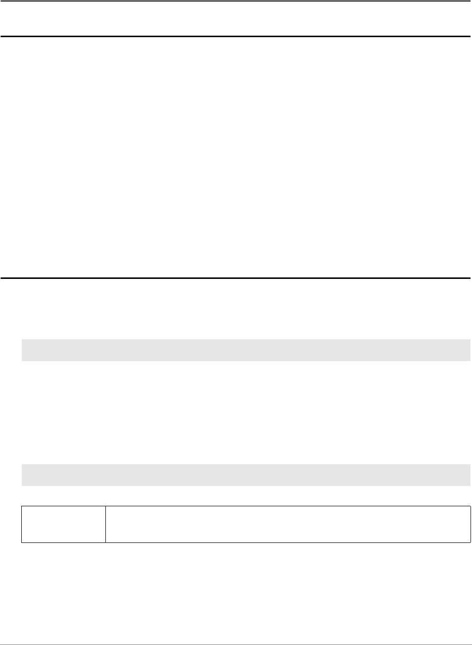
POWER DEBUG E40 plus Debug Cable
POWER DEBUG E40 provides a USB3 interface to the host computer.
POWER DEBUG E40
POWER DEBUG E40
PC or
Workstation
USB
Cable
Target
Debug
Connector
Debug Cable

TRACE32 Installation Guide | 11
©
1989-2024 Lauterbach
POWER DEBUG X50 plus Debug Cable
POWER DEBUG X50 provides:
• USB3 and Gigabit Ethernet interface to the host computer
• PODBUS EXPRESS interface to connect a TRACE32 POWERTRACE.
POWER DEBUG X50
POWER DEBUG X50
SWITCH PC or
Workstation
1 GBit Ethernet
Ethernet
Cable
Target
Debug
Connector
Debug Cable

TRACE32 Installation Guide | 12
©
1989-2024 Lauterbach
µTrace (MicroTrace)
µTrace (MicroTrace) is an all-in-one debug and trace tool especially designed for Cortex-M and
RISC-V 32-bit processors. It consists of:
• A µTrace (MicroTrace) module, that also provides 256 MByte of trace memory
• A Whisker MIPI20T-HS
The µTrace (MicroTrace) module can contain a multicore license, if a chip containing several identical cores
should be debugged.
AUX PORT V1
DEBUG/TRACE WHISKER
μTRACE
®
FOR CORTEX
®
-M / USB 3
μTRACE
®
FOR RISC-V 32-bit / USB 3
PC or
Workstation
USB
Cable
Target
MIPI 20T / MIPI 10
Connector

TRACE32 Installation Guide | 13
©
1989-2024 Lauterbach
CombiProbe
POWER DEBUG E40 plus COMBIPROBE 2
A TRACE32 CombiProbe debugger configuration consists of:
• A universal POWER DEBUG module.
• A COMBIPROBE 2 hardware, which is a debug and trace tool providing 512 MByte of trace
memory.
The COMBIPROBE 2 is licensed for the core under debug, but it can also contain a multicore
license or debug licenses for further processor architectures if a multicore chip should be
debugged.
It can also contain traces licenses mainly used to decode core trace information stored in the
CombiProbe trace memory.
• A core architecture specific CombiProbe Whisker.
POWER DEBUG E40
POWER DEBUG E40
PC or
Workstation
USB
Cable
Target
B
A
COMBIPROBE 2
CABLE
COMBIPROBE 2
COMBIPROBE
Connector
COMBIPROBE
Whisker

TRACE32 Installation Guide | 14
©
1989-2024 Lauterbach
TRACE32 Debug and Trace Tools
Debugger and Parallel/Serial Preprocessors
A TRACE32 hardware-based debug and trace tool can consist of:
• The universal debugger hardware.
• A debug cable specific to the (main) processor architecture under debug;
The debug cable can contain a multicore license or debug licenses for further processor
architectures if a multicore chip should be debugged.
• A universal trace module:
- POWER TRACE III with 4 GByte or 8 GByte of trace memory
or
- POWER TRACE II LITE with 512 MByte of trace memory and reduced characteristics.
• A parallel or serial preprocessor specific to the processor architecture and its trace protocol
The preprocessor can contain trace licenses for further processor architectures if a multicore
chip exports trace information in various trace protocols.

TRACE32 Installation Guide | 15
©
1989-2024 Lauterbach
POWER DEBUG X50 and POWER TRACE III plus Preprocessor
POWER DEBUG X50
POWER TRACE III
1
POWER DEBUG X50
POWER TRACE III
Windows Host
USB 3.0
USB
Cable
Target
Debug
Connector
Debug Cable
LAUTERBACH
LAUTERBACH
PREOPROCESSOR AUTOFOCUS II
CBA
CABLE
Trace
Connector
Preprocessor
AUTOFOCUS II

TRACE32 Installation Guide | 16
©
1989-2024 Lauterbach
Tools with PowerTrace Serial
A TRACE32 hardware-based debug and trace tool can consist of:
• The universal debugger hardware.
• A debug cable specific to the (main) processor architecture under debug;
The debug cable can contain a multicore license or debug licenses for further processor
architectures if a multicore chip should be debugged.
• A universal trace hardware POWER TRACE SERIAL 2 with up to 8 GByte of trace memory
licensed for a processor architecture and its trace protocol
POWER TRACE SERIAL 2 can contain trace licenses for further processor architectures if a
multicore chip exports trace information in various trace protocols
POWER TRACE SERIAL 2 was designed for two use cases:
• Recording trace information from high-speed Aurora-based trace ports
• Recording trace information from PCIe-based trace ports
Tracing from a PCIe-based trace port requires a License for PCI Express programmed to
POWER TRACE SERIAL 2

TRACE32 Installation Guide | 17
©
1989-2024 Lauterbach
POWER DEBUG X50 and POWER TRACE SERIAL 2
POWER DEBUG X50
POWER TRACE SERIAL 2
POWER DEBUG X50
POWER TRACE SERIAL 2
Windows Host
USB 3.0
USB
Cable
Target
Debug
Connector
Debug Cable
Serial Trace
Connector

TRACE32 Installation Guide | 18
©
1989-2024 Lauterbach
POWER DEBUG X50 and POWER TRACE SERIAL 2 and Preprocessor
POWER DEBUG X50
POWER TRACE SERIAL 2
POWER DEBUG PRO
POWER TRACE SERIAL 2
SWITCH PC or
Workstation
1 GBit Ethernet
Ethernet
Cable
Target
Debug
Connector
Debug Cable
PREPROCESSOR AURORA 2
FOR POWER TRACE SERIAL
POWER TRACE SERIAL
PORT 1
TARGET IN
LINK UP
DATA
Trace
Connector
PREPROCESSOR AURORA 2
for POWER TRACE SERIAL
4lanes @ 22 GBit/s

TRACE32 Installation Guide | 19
©
1989-2024 Lauterbach
POWER DEBUG X50 and POWER TRACE SERIAL 2 and PCIe Adapter
POWER DEBUG X50
POWER TRACE SERIAL 2
POWER DEBUG X50
POWER TRACE SERIAL 2
Windows Host
USB 3.0
USB
Cable
Target
Debug
Connector
Debug Cable

TRACE32 Installation Guide | 20
©
1989-2024 Lauterbach
Software Installation
This chapter describes the installation of TRACE32 under:
•MS Windows
- Quick Installation
- Ethernet
-USB
•PC_Linux
- Ethernet
-USB
•Mac OS
TRACE32 Installation Guide | 21
©
1989-2024 Lauterbach
MS Windows
Quick Installation
1. Install TRACE32 by double-clicking “setup.bat” or “files\bin\setup64\setup.exe”
2. Follow the on-screen instructions.
3. Upon completion of the installation, start TRACE32 via the Windows Start button as described in
“Debugger Tutorial” (debugger_tutorial.pdf).
In multicore/multiprocessor debug environments, it is recommended that Windows users start TRACE32 via
the T32Start application.
1. Start T32Start via the Windows Start button.
2. Configure T32Start according to your requirements. See chapter “Quick Start” in T32Start,
page 7 (app_t32start.pdf).
3. Configure the TRACE32 help system with a few mouse-clicks to display the PDF help files in your
favorite PDF viewer; see “Configure the Help System” in PowerView User’s Guide, page 90
(ide_user.pdf).
Ethernet
First a new node must be created for TRACE32. The Ethernet address of the debugger is on a sticker
located on the reverse side of the system. The administrator must add an entry containing the IP address
and node name to the name server, or the following line must be added to the file HOSTS:
Note, the above used IP address is an example only.
The IP address is per default requested by a DHCP/RARP protocol by TRACE32. If no DHCP/RARP server
is running, the address for the first connect must be set in the host table. After the first successful
connection, the IP address is stored in the non-volatile memory within TRACE32. The following command
sets the host translation table:
If the ARP command is not available, the IP address must be set by connecting the system via USB.
192.9.200.5 t32
arp -s t32 0-c0-8a-0-0-0
NOTE: On Windows the ARP command is only available if you are logged in as an
administrator.

TRACE32 Installation Guide | 22
©
1989-2024 Lauterbach
To use the network access, the net driver must be activated. The node name can be changed, when not
identical to 't32'.
USB Interface
The USB driver must be selected.
When the device is first connected to the system, the hardware assistant detects a new USB device and
asks for a driver directory.
If the TRACE32 software is already installed, the required file (t32usb.inf) can be found in the TRACE32
installation directory (e.g. c:\t32\). Otherwise please insert the TRACE32 installation DVD and navigate to
the directory ~~/bin/windows/drivers or let the system search for it.
Configuration Command:
PBI=
NET
Used for controller-based debugging
NODE=<node_name> (default: t32)
PACKLEN=1024 Limits the size of the UDP packages to 1024
Configuration Command:
PBI=
USB
Select PODBUS interface via USB connection
PBI=
USB
NODE=T32-ARM
Select PODBUS interface via named USB connection
The PODBUS interface is identified by a name (IFCONFIG).
A name is required if several debug modules are connected
via USB and used simultaneously.
The manufacturing default device name is the serial number
of the debug module. e.g. NODE=E18110012345

TRACE32 Installation Guide | 23
©
1989-2024 Lauterbach
PC_LINUX
The TRACE32 PowerView GUI for Linux is available in two versions:
• Qt GUI (MWI and MDI)
• Motif GUI (MWI)
Without further settings, TRACE32 will select the best available screen driver in the following order:
1. Qt5
2. Motif
Quick Installation
Common steps
TRACE32 is installed with the script setup_linux.sh. It is in the root directory of the installation source (DVD,
downloaded full installation package).
The installation script creates the following example configurations:
The following environment variables must be set (e.g. in .bashrc for the BASH-shell):
<INSTALLSOURCE>/setup_linux.sh [<INSTALLDIR>]
<INSTALLSOURCE> Directory of the installation source
<INSTALLDIR> Installation directory (default ~/t32)
config.t32 General configuration file
config_sim.t32 Configuration file for simulator
config_usb.t32 Configuration file for USB debugger
config_eth.t32 Configuration file for ETH debugger
config_hostmci.t32 Configuration file for TRACE32 as a back-end using the
Lauterbach debug driver library hostmci
export T32SYS=<INSTALLDIR>
export T32TMP=/tmp
export T32ID=T32
Set T32SYS to the installation directory

TRACE32 Installation Guide | 24
©
1989-2024 Lauterbach
The TRACE32 online help system uses an external PDF viewer for displaying the information in PDF
format.
Please execute the TRACE32 command SETUP.PDFViewer.state inside the TRACE32 PowerView GUI
once.
If the auto-detection fails, a manual setting will be necessary.
Legacy information for Acrobat Reader usage:
Download Acrobat Reader from http://www.adobe.com and install it if not already installed on the system.
Usually, you have to be root for the installation!
Set the environment variable “ACROBAT_PATH” to the Acrobat installation path::
Copy the TRACE32 plug-in into the Acrobat plug_ins folder (without new line):
Verify that you have write permission to the system directory and prepare the configuration file
config.t32:
tar -xvzf linux-508.tar.gz # or similar filename
./INSTALL # run the install script
export ADOBE_PATH=/opt/Adobe/Reader8 # added in ~/.bashrc for BASH
or
export ACROBAT_PATH=/opt/Acrobat5 # added in ~/.bashrc for BASH
cp /mnt/cdrom/files/bin/pc_linux/trace32.api
$ADOBE_PATH/Reader/intellinux/plug_ins
or
cp /mnt/cdrom/files/bin/pc_linux/trace32.api
$ACROBAT_PATH/Reader/intellinux/plug_ins
cd /opt/t32/bin/pc_linux64 # depends on the location of the actual used
# or # configuration file
cd /opt/t32 # default file location is /opt/t32 ($T32SYS)
vi config.t32 # define interface type, …

TRACE32 Installation Guide | 25
©
1989-2024 Lauterbach
Uncompress the executable files before usage (not necessary when filecvt was used before):
Include the executable file in the PATH variable:
Starting the TRACE32 executable file could be done in several ways:
Configure the TRACE32 help system with a few mouse-clicks to display the PDF help files in your
favorite PDF viewer; see “Configure the Help System” in PowerView User’s Guide, page 90
(ide_user.pdf).
…
# e.g. when using ethernet interface
PBI= #
NET # please replace t32 with the actual assigned
NODE=t32 # network node name for the ICD module
# e.g. when using USB interface
PBI=
USB
cd /opt/t32/bin/pc_linux64
gzip -d t32m*.gz
# or gunzip t32m*.gz
export PATH=$PATH:/opt/t32/bin/pc_linux64 # added in ~/.bashrc for BASH
# preferred solution
# preferred solutions
export PATH=$PATH:/opt/t32/bin/pc_linux64 # added in ~/.bashrc for BASH
./t32marm -c /opt/t32/bin/pc_linux64/config.t32
# TRACE32 executable is called with
# configuration filename parameter
# starting executable with a
# PRACTICE startup script file
./t32marm -c /opt/t32/bin/pc_linux64/config.t32

TRACE32 Installation Guide | 26
©
1989-2024 Lauterbach
Qt GUI specific steps
The minimum requirements for the Qt GUI are:
• Kernel: 3.12
• libc: 2.18
• Qt libs: 5.5
Minimum versions of some popular Linux distributions:
Font settings in the configuration file config.t32:
No special font settings are required. Each installed fixed width font can be used. The default font is
Monospace..
GUI Configuration in the configuration file config.t32:
The GUI can be configured with STYLE options in the SCREEN= section of the configuration file
config.t32. The following STYLE options can be set:
Distribution minimum release required packages
Ubuntu 14.04 libqtcore5, libqtgui5
Debian 9.0 libqtcore5, libqtgui5
Mint 18.3 libqtcore5, libqtgui5
RedHat RHEL 7 qt, qt-x11
CentOS 7.0 qt, qt-x11
Fedora 24 qt, qt-x11
SUSE 12 libqt5
openSUSE 15 libqt5
SCREEN=
FONT=Liberation Mono
FONT=NOANTIALIAS
; Selects font Liberation Mono for data output
; disables font aliasing (default: ANTIALIAS)
STYLE=STATUSBAR ON Enables the status bar of the main window (default)
STYLE=STATUSBAR OFF Disables the status bar of the main window
STYLE=TOOLBAR ON Enables the tool bar of the main window (default)
STYLE=TOOLBAR OFF Disables the tool bar of the main window
STYLE=TOOLBAR TOP Places the tool bar on the top edge of the main window
(default)

TRACE32 Installation Guide | 27
©
1989-2024 Lauterbach
1: If no predefined theme is set, the theme of the current desktop is used.
2: If no special color is set, the TRACE32 default is used.
STYLE=TOOLBAR RIGHT Places the tool bar on the right edge of the main window
STYLE=TOOLBAR BOTTOM Places the tool bar on the bottom edge of the main
window
STYLE=TOOLBAR LEFT Places the tool bar on the left edge of the main window
STYLE=COMMANDLINE TOP Places the command line and the soft keys to the top
edge of the main window (default)
STYLE=COMMANDLINE BOTTOM Places the command line and the soft keys to the bottom
edge of the main window
STYLE=MDISCROLL OFF disables MDI area scroll bars (default)
STYLE=MDISCROLL ON enables MDI area scroll bars
STYLE=SMALLSIZE Reduces the size of dialog elements (e.g. buttons, check
boxes, ...) on some systems (Ubuntu Unity, ...)
STYLE=NORMALSIZE Selects normal size of dialog elements (e.g. buttons,
check boxes, ...) on some systems (Ubuntu Unity, ...)
(default)
STYLE=FUSION
1
Selects Qt predefined theme Fusion
STYLE=CDE
1
Selects Qt predefined CDE theme
STYLE=MOTIF
1
Selects Qt predefined Motif theme
DPI=AUTO (default)
Linux only
TRACE32 uses the OS DPI rate for font scaling.
DPI=<value>
Linux only
User-defined DPI rate for font scaling.
Range: 48 to 448
DPI=NONE
Linux only
No DPI scaling.
PALETTE <n> =
<red><green><blue>
2
Change color value. Specify the colors as 8 bit per color
channel, from 0 (darkest) to 255 (lightest). all numbers
must be provided as decimals.
For CDE/Motif only: Input in 16 bit per color channel
allowed for backwards compatibility.
See also: SETUP.COLOR.

TRACE32 Installation Guide | 28
©
1989-2024 Lauterbach
Motif GUI specific steps
Prepare and install the fonts:
Since TRACE32 software release April 2010 the font installation is simplified.
It’s necessary to place a subdirectory named fonts (e.g. /opt/t32/fonts) under the TRACE32 system directory
(e.g. /opt/t32). The TRACE32 PowerView software automatically searches for the required TRACE32 fonts
in this directory if the fonts are not provided by the host operating system.
When bitmap fonts are blocked/locked from the host operating system, a usage overwrite can be activated
by adding the following lines inside the actual used TRACE configuration file e.g. config.t32.
Font installation for TRACE32 software releases older than April 2010:
The xset commands add the TRACE32 fonts only temporary. After the next booting or logout the setting will
be lost. A solution could be adding the xset commands into the login script of the actual shell from the actual
user e.g. ~/.bashrc for BASH shell or just in the batch script for starting TRACE32.
The TRACE32 fonts can be added alternatively to an existing font server configuration.
e.g. add path /opt/t32/fonts to the catalog entry inside the font server configuration file /etc/X11/fs/config.
Or add the TRACE32 fonts permanent with an administration tool.
e.g. under SUSE: N -> Control Center -> System Administration -> Font Installer
When the ’TRACE32 menu or softkey text are displayed as graphic characters under Fedora Core Linux
versions, some fonts are missing. Install them with:
SCREEN=
FONTMODE=3
; bitcoded values (0..3 allowed)
; bit0: bitmap system fonts activated
; bit1: bitmap TRACE32 client fonts activated
cd /opt/t32/fonts
mkfontdir ./
xset +fp /opt/t32/fonts
xset fp rehash
# must be done under the original
# Xserver user (normally not as root)
# only temporary adding of TRACE32
# font directory or
chkfontpath -a /opt/t32/fonts # permanent adding of the fontdirectory
# not available under SUSE distribution
ln -s /opt/t32/fonts
/etc/X11/fontpath.d/t32-fonts
# permanent adding of the fontdirectory
# available under FEDORA distribution
yum install xorg-x11-fonts-ISO8859-1-75dpi

TRACE32 Installation Guide | 29
©
1989-2024 Lauterbach
Ethernet Interface
Before the installation a new node must be created. The Ethernet address of the system is placed on the
bottom side of the system. The following line must be added to the file
/etc/hosts:
Note that the IP address given here is an example only.
The Ethernet address of the system must be entered in the file /etc/ethers (not common - only when using a
RARP server):
The IP address is requested by a RARP protocol by TRACE32. If no RARP server is running, the address
for the first connect must be set in the host table. After the first successful connect the IP address is stored in
nonvolatile memory within TRACE32. The following command sets the host translation table:
This command must be executed immediately before the first startup of the debugger. It is not required for
future startups because the IP address is stored in the debugger. The arp cache table should be checked
just before the first startup with the command
'arp -a'.
NOTE: A ping will only work after the TRACE32 software was booted once and the new IP address was
stored automatically during boot phase into the flash of the TRACE32 module.
The net driver must be activated. The node name can be changed, when not identical to 't32'.
192.168.0.5 t32
0:c0:8a:0:0:0 t32
arp -s t32 0:c0:8a:0:0:0
Configuration Command:
PBI=
NET
NODE=<node_name> Node name of TRACE32 (default: t32)
POOL=<node_name>, … Define a set of nodes, which are scanned for connection.

TRACE32 Installation Guide | 30
©
1989-2024 Lauterbach
USB Interface
In addition to the generic requirements, USB needs:
UDEV method (kernel >= 2.6):
The newer udev file system support needs a special rule file for TRACE32 USB devices inside the directory
/etc/udev/rules.d/.
Legacy support of hotplug method (devfs):
The hotplug package is no strict requirement, but highly recommended, if you want to avoid running the
TRACE32 executables as root all the time.
To enable proper TRACE32 hotplugging, change to the directory on the DVD (or with an extracted update)
with the Linux executables and issue the following commands in a shell:
You can verify proper operation with the t32usbchecker tool coming with the CD or update.
kernel >= 2.4 for FullSpeed USB support (12 MBit/s)
kernel >= 2.4.22 for HighSpeed USB support (480 MBit/s)
udev filesystem requires kernel >= 2.6
or
usbdevfs mounted on /proc/bus/usb and hotplug package
su
cp bin/pc_linux64/udev.conf/kernel_starting_2.6.32/10-lauterbach.rules /etc/udev/rules.d
su
grep -iq trace32 /etc/hotplug/usb.usermap || cat usb.usermap.trace32
>>/etc/hotplug/usb.usermap
install -m 0755 trace32 /etc/hotplug/usb/
exit

TRACE32 Installation Guide | 31
©
1989-2024 Lauterbach
The USB driver must be activated.
Configuration Command:
PBI=
USB
Select PODBUS interface via USB connection
PBI=
USB
NODE=T32-ARM
Select PODBUS interface via named USB connection
The PODBUS interface is identified by a name (IFCONFIG).
A name is required if several debug modules are connected
via USB and used simultaneously.
The manufacturing default device name is the serial number
of the debug module. e.g. NODE=E18110012345

TRACE32 Installation Guide | 32
©
1989-2024 Lauterbach
Mac OS
Prerequisites
The TRACE32 debug software for the Mac requires OS X 10.7 or newer.
Installation of the TRACE32 Software
TRACE32 is installed with the script setup_macos.sh. It is in the root directory of the installation source
(DVD, downloaded full installation package).
The installation script creates the following example configurations:
The following environment variables must be set (e.g. in .bashrc for the BASH-shell):
Include the executable file in the PATH variable:
Configure TRACE32
Verify that you have write permission to the system directory (set with environment variable T32SYS) and
edit the configuration file config.t32.
<INSTALLSOURCE>/setup_macos.sh [<INSTALLDIR>]
<INSTALLSOURCE> Directory of the installation source (DVD,
<INSTALLDIR> Installation directory (default ~/t32)
config.t32 General configuration file
config_sim.t32 Configuration file for simulator
config_usb.t32 Configuration file for USB debugger
config_eth.t32 Configuration file for ETH debugger
config_hostmci.t32 Configuration file for TRACE32 as a back-end using the
Lauterbach debug driver library hostmci
export T32SYS=<INSTALLDIR>
export T32TMP=/tmp
export T32ID=T32
Set T32SYS to the installation directory
# or similar
export PATH=$PATH:~/t32/bin/macosx64 # added in ~/.bashrc for BASH

TRACE32 Installation Guide | 33
©
1989-2024 Lauterbach
Interface setting:
Ethernet interface
For the adaptation to ethernet a new node must be created. The following line must be added to the file
/etc/hosts:
Note that the IP address given here is an example only. Add the following lines to your config.t32 file:
USB interface
Add the following lines to your config.t32 file
192.168.0.5 t32
PBI=
NET # please replace t32 with the actual
NODE=t32 # assigned nodename for the ICD module
PBI=
USB

TRACE32 Installation Guide | 34
©
1989-2024 Lauterbach
Fontsettings :
No special font settings are required. Each installed fixed width font can be used. The default font is Menlo..
GUI Configuration:
The GUI can be configured with STYLE options in the SCREEN section of the configuration file. The
following STYLE options can be set:
SCREEN=
FONT=Liberation Mono
FONT=NOANTIALIAS
; Selects font Liberation Mono for data output
; disables font aliasing (default: ANTIALIAS)
STYLE=STATUSBAR ON Enables the status bar of the main window (default)
STYLE=STATUSBAR OFF Disables the status bar of the main window
STYLE=TOOLBAR ON Enables the tool bar of the main window (default)
STYLE=TOOLBAR OFF Disables the tool bar of the main window
STYLE=TOOLBAR TOP Places the tool bar on the top edge of the main window
(default)
STYLE=TOOLBAR RIGHT Places the tool bar on the right edge of the main window
STYLE=TOOLBAR BOTTOM Places the tool bar on the bottom edge of the main
window
STYLE=TOOLBAR LEFT Places the tool bar on the left edge of the main window
STYLE=COMMANDLINE TOP Places the command line and the soft keys to the top
edge of the main window (default)
STYLE=COMMANDLINE BOTTOM Places the command line and the soft keys to the bottom
edge of the main window
STYLE=MDISCROLL OFF disables MDI area scroll bars (default)
STYLE=MDISCROLL ON enables MDI area scroll bars

TRACE32 Installation Guide | 35
©
1989-2024 Lauterbach
Configuration File
The configuration file for the system defines the drivers to be installed in the host. By default the software
running on the host, assumes that the configuration file is in the system directory and named 'config.t32'. But
this can be overruled by specifying the configuration file in the environment variable T32CONFIG. The
configuration file can be defined by a command line option (-c).
The configuration file is split into sections. Each section is started by the first line following an empty line. A
section ends with an empty line. So a section is a block of contiguous lines, which are not interrupted by an
empty line. The first line of a section defines what kind of section it is. The first line is the section header and
should look like this:
The section “Variation” is optional and only needed for specific use cases. It is often left out.
Example: section header for the OS section:
Example: section header for the PBI section, setting up an instruction set simulator:
The section header is followed by a list of key-value pairs. Each key-value pair looks like this:
Note that the “key value” might be left out for specific key names; so there are key names which do not
expect a following key value.
Example: section SCREEN to give TRACE32 PowerView a custom title:
Configuration files are space sensitive and sensitive to empty lines!
<Section Name>=[<Variation>]
OS=
PBI=SIM
<key name>[=<key value>]
SCREEN=
TITLE=My own title for TRACE32 PowerView

TRACE32 Installation Guide | 36
©
1989-2024 Lauterbach
The configuration file can contain comments. Comments are line based. A comment is started with a ‘;’ as
the first character in a line. Comment lines do not count as empty lines, so a comment line does not end a
section.
Example: section SCREEN to give TRACE32 PowerView a custom title:
The configuration file might be parametrized by using environment variables and command line parameters.
To refer to an operation system environment variable, you can use:
Example: use the environment variable T32NODE as the definition of the Ethernet node, and the first
command line argument will be used as the window title:
You can also generate ‘hierarchical’ configuration files by using include files:
This allows to keep some configuration information local (e.g. in the home directory of the user by using the
environment variable T32CONFIG), and share the rest of the configuration with other systems.
SCREEN=
; give the window a different title:
TITLE=My own title for TRACE32 PowerView
${<environment variable name>}
; Use node name from environment variable, title from command line
PBI=
NET
NODE=${T32NODE}
SCREEN=
TITLE=${1}
$INCLUDE /usr/t32/config.all
SCREEN=
PALETTE 0 = 12 34 56
;…

TRACE32 Installation Guide | 37
©
1989-2024 Lauterbach
Section “OS”
This optional section is mainly used to specify TRACE32 paths. If this section is missing, TRACE32 tries to
detect the paths based on the location of the TRACE32 executable. The section header does not expect a
“Variation” value.
OS=
ID=T32
TMP=C:\temp
SYS=C:\T32
HELP=C:\T32\pdf
COREFCC=C:\T32\crashfiles
Key/value Description
ID=<id> Prefix for all files that are saved by the TRACE32 PowerView
instance into the TMP directory.
HELP=<path> Directory where the pdf-files for the TRACE32 online help are
located.
SYS=<path> This key specifies the installation directory of TRACE32. If
this directory is not specified explicitly, TRACE32 will try to
guess the installation directory by analyzing the path of the
executable.
TMP=<path> Path to the temporary directory. If this path is not specified,
TRACE32 will use a default path.
COREFCC=<path> Defines a crashfile directory.

TRACE32 Installation Guide | 38
©
1989-2024 Lauterbach
Section LICENSE
If a setup without hardware is used, then the location of the license server can be specified with this section.
Section SCREEN
This optional section specifies various settings for the graphical user interface. If the SCREEN section is used
with the Variation OFF, TRACE32 is started without a graphical user interface. For details, see below.
Key/value Description
RLM_LICENSE=<port@server> The value of this key specifies how to contact a floating
license server. Example:
LICENSE=
TIMEOUT=<time> Allows to automatically return checked out but unused licenses.
The value of this parameter holds the minutes of inactivity before
licenses are returned. A minimum of 15 minutes is defined.
Setting the optional parameter to zero (TIMEOUT=0) is the
same as no such line and will result in never automatically
returning unused floating licenses. Inactivity in the context of this
parameter is time spent in down state.
POOLPORT=<number> TCP/IP port for license pool. Refer to the chapter “Floating
License Pools” in Floating Licenses, page 20
(floatinglicenses.pdf) for more information.
Key/value Description
TITLE=<title> Specifies the title of the TRACE32 PowerView user interface.
HEADER=<title> Same as TITLE
MDI MDI Multiple Document Interface (default)
All child windows appear inside the TRACE32 main window.
FDI Floating Document Interface
All child windows can be placed on any position on the
desktop independently form the main window. Minimizing the
main window, minimizes also the child windows. Only the
main window appears in the task bar.
MTI Multiple Top-level window Interface
All child windows can be placed on any position on the
desktop independently form the main window. Minimizing the
main window, minimizes none of the child windows.
Both the main and all child windows appear in the task bar.

TRACE32 Installation Guide | 39
©
1989-2024 Lauterbach
TRACE32 as a Hidden Instance
There are three ways to configure TRACE32 to start as a hidden instance. Choose one of the configuration
options:
Option 1:
MWI Multiple Window Interface (obsolete alias for FDI).
See FDI
INVISIBLE The main window of TRACE32 remains hidden. However,
dialogs and other windows of TRACE32 can still be opened.
For details, see below.
PALETTE <n> =
<red><green><blue>
Change color value, the intensities will vary from 0 to 255.
FONT=SMALL Use small fonts (13x7 instead of 16x8). Alternatively, you can
use MEDIUM or LARGE.
TEXTFONT=<font_name> Use the specified font for text windows. The specified font
must either match the size of the regular TRACE32 fonts, or
must be a TrueType fixed pitch font. Examples for such fonts
are "Courier New" or "Lucida Console".
CHARSET=<number> Text windows and menus use the specified character set.
MINCHO Use MS-Mincho character set (Japanese)
DPI=AUTO (default)
Linux only
TRACE32 uses the OS DPI rate for font scaling.
DPI=<value>
Linux only
User-defined DPI rate for font scaling.
Range: 48 to 448
DPI=NONE
Linux only
No DPI scaling.
VLINES=<lines> Startup size lines (default 35)
VCOLUMNS=<col> Startup size columns (default 81)
VICON Startup iconized (minimized). For details, see below.
VFULL Startup full screen (maximized)
HEADER=<name> Header text for the TRACE32 main window
LINES=<lines> Max. number of lines (default 55)
COLUMNS=<col> Max. number of columns (default 144)
other Other commands are available for special purposes, they are
not used in standard environments.
Key/value Description

TRACE32 Installation Guide | 40
©
1989-2024 Lauterbach
The main window of TRACE32 remains hidden. However, dialogs and other window of TRACE32 can still
be opened. This is useful, for example, if an error occurs during a regression test.
Option 2:
The main window of TRACE32 and all other dialogs and windows of TRACE32 remain hidden - even if an
error occurs.
Option 3:
The main window of TRACE32 is added to the toolbar of the host computer. It can be fully displayed in case
of an error.
Japanese Font
The following example uses a Japanese font for text display.
You can also define the window position and size of TRACE32 using the FramePOS command or the
CmdPOS command.
SCREEN=
INVISIBLE
NOTE:
• INVISIBLE must be written below SCREEN= in the config.t32 file.
• On UNIX machines, the configuration option 1 requires a running X
server.
SCREEN=OFF
NOTE:
• OFF must be written in the same line as SCREEN= in the config.t32 file.
• On Unix machines, the configuration option 2 does NOT require a run-
ning X server.
• However, the X libraries must be installed.
SCREEN=
VICON
SCREEN=
TEXTFONT=@MSxxxx
CHARSET=128
; the Japanese font name cannot be reproduced here

TRACE32 Installation Guide | 41
©
1989-2024 Lauterbach
Section PRINTER
Configuration Command:
PRINTER=<type> printer type (RAW,NEC,LJ,PS,WINDOWS)
RAW: simple printer without graphics
NEC: NEC compatible printer
LJ: Laserjet compatible printer
PS: Postscript printer
WINDOWS: Windows native printer
Commands:
DEV=<path> device name or file name
SPOOL=<cmd> command is executed after printing
IBMSET use PC-8 character set
for HP-Laserjet II
NOR Don't use reverse feed (e.g. CANON LJ-600)
Only for NEC printer driver.
TRACE32 Installation Guide | 42
©
1989-2024 Lauterbach
Section PBI
The PBI (PodBus Interface) section specifies the basic functionality of the TRACE32 debugger.
Section PBI= (without variation)
If no explicit “Variation” is specified, the default “Variation” ICD is used, which connects to a PowerDebug
device.
Examples:
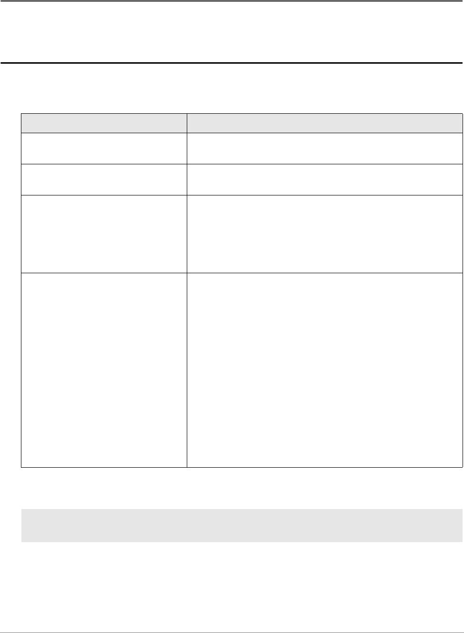
Key/value Description
USB Connect to the PowerDebug device via a USB connection.
This key does not have a key value.
NET Connect to the PowerDebug device via a network connection.
This key does not have a key value.
NETTCP Only for PowerDebug X50.
When NET is used, a handshake is performed over UDP
between TRACE32 PowerView and the PowerDebug module
then the communication is switched to TCP.
This initial UDP handshake is skipped if NETTCP is used
instead of NET.
NODE=<node_name> The key value specifies the node name of the PowerDebug
device to connect to.
If a network connection is used, this should be either a DNS
name or an IP address.
If an USB connection is used, the node name is checked
against the PowerDebug devices connected via USB.
Each PowerDebug device has a node name, which is stored
in the hardware. This node name might be changed via the
TRACE32 software using the command IFCONFIG. If the
specified node name matches to the node name found in the
PowerDebug device then the connection is made to this
PowerDebug device. For USB this is useful if you have more
than one PowerDebug device connected via USB. If only one
PowerDebug device is connected to your PC, you might leave
out the node name. In this case TRACE32 will connect to the
first found PowerDebug device connected via USB.
PBI=
USB
; PowerDebug is connected to the PC via USB

TRACE32 Installation Guide | 43
©
1989-2024 Lauterbach
Connection Modes
PBI=
USB
NODE=T32-ARM
; PowerDebug is connected to the PC via USB
; the TRACE32 development tool is identified by
; a device name, which is required if several
; PowerDebug modules are connected via USB to the
; PC. The manufacturing default device name is
; the serial number of the debug module
PBI=
NET
NODE=T32-ARM
; PowerDebug is connected to the host via
; Ethernet
NOTE: PBI=NET starts TRACE32 PowerView as a monitor program for connection
over Ethernet (Serial Monitor). To connect to the PowerDebug device via a
network connection, the keyword NET needs to be added to the next line as
shown in the example above.
The connection modes are not applicable for multi-core debugging.
Key/value Description
CONNECTIONMODE=AUTOABORT If PowerDebug device is already in use, the
TRACE32 executable will be closed
automatically without any user interaction.
CONNECTIONMODE=AUTOCONNECT The TRACE32 executable will automatically take
over control over the PowerDebug device, even
if the debugger is already in use.
CONNECTIONMODE=AUTORETRY If PowerDebug device is already in use, the
TRACE32 executable will wait until the current
TRACE32 session ends.
CONNECTIONMODE=NORMAL If PowerDebug device is already in use, warn
user and close application after confirmation.
CONNECTIONMODE=QUERYCONNECT If PowerDebug device is already in use, ask user
if connection shall be forced.

TRACE32 Installation Guide | 44
©
1989-2024 Lauterbach
Special Commands
Key/value Description
AUTOABORT
AUTOCONNECT
AUTORETRY
obsolete - please use CONNECTIONMODE=<mode>
instead
CORE=<number> If you intend to debug with an AMP (Asymmetric Multi-
Processing) session, you need to start several TRACE32
PowerView instances, which all use the same PowerDebug
device. In this case, each started executable needs a unique
number, called here “core number”. This number is used as
an index, which identifies the executable on the PowerDebug
device.
CORE=0 means the TRACE32 executable that uses this
setting in a config file has exclusive access to a particular
PowerDebug module. No other TRACE32 executable can
connect to this particular PowerDebug module.
You can return the value of CORE with the
SYStem.USECORE() function.
INSTANCE=<number> Defines the internal communication channel between
TRACE32 executable and debug interface. Set to 0 for single-
core debugging (default if not specified). For multi-core
debugging (several instances of TRACE32 connect to the
same debugger module), use a unique number between
1..16 for each instance.
You can return the value of INSTANCE with the
SYStem.INSTANCE() function.
HOSTPORT=<port> Defines the UDP communication port from the debugger
module to the PC (default is PORT+n)
PORT=<port> Sets the UDP communication port from the PC to the
debugger module (default is 20000). For AMP, all instances
must use the same port number.
SMALLBLOCKS It restricts the default communication block size to 4.5 KBytes
instead of 16KB. This may avoid problems with network
equipment which have resource restrictions (e.g. internal
buffer overflows)
USE=<bits> The USEMASK selects the Lauterbach device, when several
devices are connected to each other via PODBUS IN/OUT.
For a description and an example, see SYStem.USEMASK()
function.

TRACE32 Installation Guide | 45
©
1989-2024 Lauterbach
PROXYNAME=<ip_address>
PROXYPORT=<port_number>
TRACE32 allows to communicate with a POWER DEBUG
INTERFACE USB from a remote PC.
For an example, see “Example: Remote Control for POWER
DEBUG INTERFACE / USB”, page 46.
CONNDELAY=<value> Delays the connection with the given time. Only applicable for
network connections.
DNSRETRIES=<n> Default: DNSRETRIES=0
Sets the number of retries when trying to resolve a DNS
name of a TRACE32 device on start-up of the host software.
Before each retry there is a 1 second wait time.
Only applicable for network connections.
Key/value Description

TRACE32 Installation Guide | 46
©
1989-2024 Lauterbach
Example: Remote Control for POWER DEBUG INTERFACE / USB
TRACE32 allows to communicate with a POWER DEBUG INTERFACE USB from a remote PC.
In order to implement this communication, the command line tool t32tcpusb has to be started on the PC to
which the POWER DEBUG INTERFACE USB is connected. t32tcpusb can be found in the
bin/<target_os> directory of your TRACE32 installation (e.g. bin/windows64).
On the remote host computer the configuration file for USB has to be extended as follows:
t32tcpusb <port_number> The default port number is 8455
t32tcpusb 8866
Parameter Syntax Description
Host interface PBI=
USB
PROXYNAME=<ip_address>
PROXYPORT=<port_number>
<ip_address> of PC that runs t32tcpusb
<port_number> that was specified when
t32tcpusb was started
POWER DEBUG E40
POWER DEBUG INTERFACE / USB 3
USB
Cable
Targ et
Debug
Connector
Debug Cable
PC
TRACE32 - PowerView
TCP / IP
Windows / Linux
PC
t32tcpusb
Windows / Linux

TRACE32 Installation Guide | 47
©
1989-2024 Lauterbach
In case of several PowerDebug modules connected via USB and used simultaneously, it is required to
identify each of them by a name using the command IFCONFIG. If the node name specified in the
configuration matches the node name found in the PowerDebug device, the connection is made to this
PowerDebug device.
; Host interface
PBI=
USB
PROXYNAME=10.2.20.142
PROXYPORT=8866
; Environment variables
OS=
ID=T32
TMP=C:\temp
SYS=C:\t32
HELP=C:\t32\pdf
; temporary directory for TRACE32
; system directory for TRACE32
; help directory for TRACE32
; Printer settings
PRINTER=WINDOWS
; all standard windows printer can be
; used from the TRACE32 user interface
; Host interface
PBI=
USB
NODE=T32-Arm
PROXYNAME=10.2.20.142
PROXYPORT=8866
…

TRACE32 Installation Guide | 48
©
1989-2024 Lauterbach
Section PBI=<driver>
TRACE32 PowerView GUI is used without a LAUTERBACH.
PBI=<driver> Description
PBI=SIM start a TRACE32 Instruction Set Simulator.
PBI=*SIM
USB
start a TRACE32 Instruction Set Simulator which is licensed
using a hardware-based TRACE32 debugger connected to the
host computer via USB.
PBI=*SIM
NET
NODE=<node_name>
start a TRACE32 Instruction Set Simulator which is licensed
using a hardware-based TRACE32 debugger connected to the
host computer via Ethernet.
PBI=<driver> Description
PBI=GDB start a TRACE32 GDB Front-End. Refer to “TRACE32 as GDB
Front-End” (frontend_gdb.pdf) for more information.
PBI=MDI start TRACE32 to debug via MDI (MIPS Debug Interface)
simulator. Refer to “Virtual Targets User’s Guide”
(virtual_targets.pdf) for more information.
PBI=SCS start TRACE32 to debug via the SCS StarCore simulator
PBI=SIMTSI start TRACE32 to debug via the Target Server from Texas
Instruments. Refer to “Virtual Targets User’s Guide”
(virtual_targets.pdf) for more information.
PBI=IRIS [<library_file>] start TRACE32 to debug via Iris Interface primarily Arm’s Fast
Models. Refer to “Virtual Targets User’s Guide”
(virtual_targets.pdf) for more information.
PBI=CADI [<library_file>] start TRACE32 to debug via the Arm Cycle Accurate Debug
Interface CADI. Refer to “Virtual Targets User’s Guide”
(virtual_targets.pdf) for more information.
PBI=GDI [<library_file>] start TRACE32 to debug via the Generic Debug Instrument
Interface GDI. Refer to “Virtual Targets User’s Guide”
(virtual_targets.pdf) for more information.
PBI=HOST start TRACE32 as host process debugger. Refer to “Native
Process Debugger” (windows_debugger.pdf) for more
information.
PBI=NET start TRACE32 as monitor program for connection over
Ethernet (Serial Monitor).

TRACE32 Installation Guide | 49
©
1989-2024 Lauterbach
PBI=MCD [<library_file>] start TRACE32 to debug via the MultiCore Debug interface
MCD. Refer to “Virtual Targets User’s Guide”
(virtual_targets.pdf) for more information.
PBI=DLL <dll> start TRACE32 for debugging via a monitor program on the
target. Communication is performed with a user-defined DLL.
PBI=ARCINT start TRACE32 for debugging using the ARCINT interface.
Refer to “Simulator for ARC” (simulator_arc.pdf) for more
information.
PBI=<driver> Description

TRACE32 Installation Guide | 50
©
1989-2024 Lauterbach
Section PBI=MCISERVER
The TRACE32 PowerView GUI can be used without any LAUTERBACH hardware as debug back-end. This
section describes the configuration file options for debug back-ends.
PBI=<driver> Description
PBI=MCISERVER start a TRACE32 as a back-end using an MCI server
(t32mciserver). Refer to “Section PBI=MCISERVER”, page 50
for details about key/value pairs specific to this section.
See “TRACE32 Debug Back-Ends” (backend_overview.pdf)
for use scenarios for this setup.
PBI=MCILIB start a TRACE32 as a back-end using the Lauterbach debug
driver library hostmci.
See “TRACE32 Debug Back-Ends” (backend_overview.pdf)
for use scenarios for this setup.
Key/value Description
AUTOSTART starts an instance of t32mciserver when the server has not
started yet at local host and the option DEDICATED is also
set. Do use this option wen t32mciserver must be started at a
certain point in time or special parameters.

TRACE32 Installation Guide | 51
©
1989-2024 Lauterbach
Section RCL=NETASSIST
If such a section is present, TRACE32 opens up a Remote API UDP port, by which TRACE32 can be
remote controlled via an external application. Refer to “API for Remote Control and JTAG Access in C”
(api_remote_c.pdf) for more information.
If you want to connect with more than one external application to TRACE32 via UDP, you need several
RCL=NETASSIST sections. Each section opens up one Remote API UDP port on the specified port
number.
Section RCL=NETTCP
If such a section is present, TRACE32 opens up a Remote API TCP port, by which TRACE32 can be
remote controlled via an external application. Refer to “API for Remote Control and JTAG Access in C”
(api_remote_c.pdf) for more information.
DEDICATED Prohibits to start the integrated MCI-server when there is no
response from an already started MCI-server at localhost.
Use this option when t32mciserver shall be started explicitly
at localhost.
NODE IP address or hostname of MCI-Server. In ideal case this
must be a machine with very low latency (<100us) to the
target. The localhost is used as hostname when NODE is left
out. An integrated MCI-server is started when NODE is
localhost and the option DEDICATED is left out. The
integrated MCI-server runs in the first started GUI. An
instance of t32mciserver as dedicated MCI-server is started
when NODE is localhost and the options DEDICATED and
AUTOSTART are used. A dedicated MCI-server should be
used when interaction with the console is required or to keep
the latency small by running it at the simulation/emulation
host.
PORT TCP-port number of MCI-Server. All started PowerView GUIs
that belong to one target system must use the same PORT
and NODE in order to connect to the same MCI-server. The
used port of the dedicated MCI-Server is passed by a
command line parameter of t32mciserver[.exe]. The port
number 30000 is used as TCP-port when the PORT option is
left out.
Key/value Description
PORT=<port_number> Specifies which UDP port number is used. If this key is
missing, the UDP port number 20000 is used per default.
PACKLEN=<value> Specifies the maximum data package length used for UDP.
Key/value Description

TRACE32 Installation Guide | 52
©
1989-2024 Lauterbach
You only need one RCL=NETTCP section, because TRACE32 already handles multiple connections to
remote applications via TCP.
Section IC=NETASSIST
If you have several TRACE32 PowerView instances running, these instances can talk to each other via the
"InterCom" mechanism.
You can only talk to a TRACE32 PowerView instance via this mechanism, if the corresponding configuration
file contains a IC=NETASSIST section.
An alternative to setting up such an InterCom port via the configuration file is to use the PRACTICE
command TargetSystem.NewInstance.
Section GDB=NETASSIST
If this section is used in the configuration file, TRACE32 PowerView is configured as GDB Back-End. Refer
to “TRACE32 as GDB Back-End” (backend_gdb.pdf) for more information.
Key/value Description
PORT=<port_number> Specifies which TCP port number is used. If this key is
missing, the TCP port number 20000 is used per default.
Key/value Description
PORT=<port_number> Specifies which UDP port number by which this TRACE32
PowerView instance is reachable. If this key is missing, the
UDP port number 10000 is used per default.
PACKLEN=<value> Specifies the maximum data package length used for UDP.
Key/value Description
PORT=<port_number> Specifies which UDP port number by which this TRACE32
PowerView instance is reachable. If this key is missing, the
UDP port number 30000 is used per default.
PACKLEN=<value> This specifies the maximum package length in bytes for the
socket communication.
PROTOCOL=<TCP | UDP> This specifies the used protocol (TCP or UDP);
Optional: the default protocol is TCP.

TRACE32 Installation Guide | 53
©
1989-2024 Lauterbach
Section TCF=
If this section is used in the configuration file, TRACE32 PowerView is configured as TCF agent. Refer to
“TRACE32 as TCF Agent” (app_tcf_setup.pdf) for more information.
Section SIMULINK=NETASSIST
This section enables the port for code-to-model navigation when the TRACE32 integration for Simulink is
used. Refer to “Integration for Simulink” (int_simulink.pdf) for more information.
Key/value Description
PORT=<port_number> Use a fixed port number. If a port number is specified, TCF
discovery mechanism is disabled.
Key/value Description
PORT=<port_number> Port for code to model navigation.

TRACE32 Installation Guide | 54
©
1989-2024 Lauterbach
Command Line Arguments for Starting TRACE32
TRACE32 can be started with and without command line arguments. If you do not pass any command line
arguments, the following default will be used:
• For the configuration file, the first available file from the following locations will be used:
- The file specified by the environment variable T32CONFIG
- The file config.t32 from the working directory (from where TRACE32 was started).
- The file config.t32 from the TRACE32 system directory (usually C:\t32)
• After the start of a TRACE32 instance, the PRACTICE script autostart.cmm from the TRACE32
system directory will be executed, which then calls the following scripts:
- system-settings.cmm (from the TRACE32 system directory, usually C:\t32)
- user-settings.cmm (from the user settings directory, on Windows %APPDATA%\TRACE32 or
~/.trace32 otherwise)
- work-settings.cmm (from the current working directory)
If you pass command line arguments, you can adapt the start and the environment of TRACE32 to your
project-specific needs. You can define a user-specific name and location for the configuration file and your
own PRACTICE start-up script. In addition, you can pass user-defined parameters to your configuration file
and to your start-up script.
The command line syntax for Windows, Linux, and Unix is as follows:
Format: t32m<arch>[.<x>] [<options>] [-c <config_file> [<c_args>]] [-s <startup_script>
[<s_args>]]
-c <config_file> By default, TRACE32 expects to find the configuration file config.t32 in the
same folder as the TRACE32 executable. An error message is displayed if the
configuration file config.t32 does not exist.
-c <config_file> allows you to define a user-specific name and location for
the TRACE32 configuration file.
For information about the configuration options in the configuration file,
type at the TRACE32 command line: HELP.Index "config.t32"
NOTE:
• -c is case sensitive, i.e. -C results in an error.
• The name of the <config_file> must not start with a hyphen and
must not contain any commas.

TRACE32 Installation Guide | 55
©
1989-2024 Lauterbach
-s <startup_
script>
When a TRACE32 instance starts, the PRACTICE script autostart.cmm is
executed, which then calls the following scripts:
• system-settings.cmm (from the TRACE32 system directory, usu-
ally C:\t32)
• user-settings.cmm (from the user settings directory: on Windows
%APPDATA%\TRACE32 or ~/.trace32 otherwise)
• work-settings.cmm (from the current working directory)
With the command line option -s <startup_script> you can specify an
additional PRACTICE script (*.cmm) which is automatically started
afterwards.
NOTE: If you use command line option -s <startup_script> but don’t have
the file autostart.cmm in your TRACE32 system directory, only the file
specified by the command line option -s will be executed.
If you don’t use the command line option -s <startup_script> and don’t
have the file autostart.cmm either, TRACE32 will fall back to a legacy
mode and execute the script t32.cmm from the working directory or from
the TRACE32 system directory if the t32.cmm does not exist in the
working directory.
<arch> Architecture, e.g. ARM in t32marm.exe stands for the ARM architecture.
<c_args> Sequence of white-space separated arguments passed to the
configuration file.
The individual command line arguments are assigned to the configuration
options in the configuration file using ${n} where n is the number of the
command line argument. The numbering starts at 1
Example: HEADER=${2} means that the second <c_arg> is assigned to
the configuration option HEADER=
NOTE: The <c_args> must not start with a hyphen and must not contain
any commas.

TRACE32 Installation Guide | 56
©
1989-2024 Lauterbach
<options> The following command line options are available for all architectures:
• --t32-help
Lists all available command line options and suppresses the auto-
matic execution of any PRACTICE script after starting TRACE32.
• --t32-help-diag
Prints all found unknown command line options into the message
AREA window.
• --t32-cmdline-quote-all
Passes all parameters to the start-up script enclosed in double
quotes.
• --t32-cmdline-quote-esc
Passes all parameters to start-up script enclosed in double quotes.
Additionally the command line option escapes already included
double quotes in parameters, so that you get the same character
sequence when accessed with PRACTICE.ARG().
• --t32-area-size-lines=<lines>
Sets the initial number of lines in the message AREA window.
• --t32-bootstatus
Prints a message to the console after the software and hardware
initialization has completed. Sets the event
T32_STARTUP_COMPLETED on MS Windows, if it exists.
• --t32-safestart
Suppresses the automatic execution of any PRACTICE script after
starting TRACE32.
• --t32-logautostart
Internally executes the LOG.DO command to generate an autostart
log in the temporary directory of TRACE32. The resulting autostart
log file lists all PRACTICE scripts which were called during start-up
of TRACE32.
For an example and a description of the file name convention, see
below.
• --t32-screen=<screendriver>
Set the screen driver used to display all PowerView windows.
Possible values area: auto, cde, qt, qt4, qt5
<s_args> Sequence of white-space separated arguments passed to the PRACTICE
start-up script (*.cmm).
All characters are permissible. However, if an <s_arg> is enclosed in
quotation marks (e.g. "Hello"), then the <s_arg> must not be interrupted
by another quotation mark.
An <s_arg> that contains one or more blanks must be enclosed in
quotation marks (e.g. "Hello World").
<x> The file name extension of the executable is optional on Windows.
(no extension for Linux and Unix)

TRACE32 Installation Guide | 57
©
1989-2024 Lauterbach
Examples
• Example 1: Logging PRACTICE script calls with --t32-logautostart during start-up of TRACE32
• Example 2: Passing command line arguments via a Windows shortcut to TRACE32
• Example 3: Passing command line arguments to a TRACE32 configuration file (*.t32)
• Example 4: Passing command line arguments to a PRACTICE start-up script (*.cmm)
• Example 5: Returning environment variables in a PRACTICE start-up script (*.cmm)
Example 1: Logging PRACTICE script calls during start-up of TRACE32 with --t32-logautostart
[Back to Top]
In this example, a Windows batch file (*.bat) sets the folder C:\T32\project_c as the working directory for
TRACE32. The next script line starts the TRACE32 executable for ARMv8 by using the configuration file
config.t32 file and the PRACTICE start-up script sieve.cmm from the working directory.
The command line option --t32-logautostart causes the autostart log file to be generated.
The caret sign ^ serves as a line continuation character in Windows batch files (*.bat). White space
characters after ^ are NOT permissible.
To access the autostart log file in TRACE32:
C:
cd C:\T32\project_c
start C:\T32\bin\windows64\t32marm.exe --t32-logautostart ^
-c config.t32 ^
-s sieve.cmm

TRACE32 Installation Guide | 58
©
1989-2024 Lauterbach
1. Execute your *.bat file to start TRACE32.
The autostart log file is generated automatically.
2. Choose File menu > Automatic Scripts on Start > View Autostart log.
The file opens in the TYPE window. The screenshot shows an example of an autostart log file:
File name convention of the autostart log file: ~~~/<id>_t32m<arch>_<xx>_autostart.log
A The file name convention of the autostart log is described below.
B The log file header tells you how the autostart log was generated. For alternatives, see “Logging
the Call Hierarchy of PRACTICE Scripts” in PRACTICE Script Language User’s Guide,
page 17 (practice_user.pdf).
~~~ Path prefix of the temporary directory of TRACE32. See also
OS.PresentTemporaryDirectory().
<id> ID of the PowerView GUI that was started. See also OS.ID().
t32m<arch> Name of the PowerView executable (without file extension), e.g.
“t32marm”
<xx> The instance number of the PowerView executable.
B
A

TRACE32 Installation Guide | 59
©
1989-2024 Lauterbach
Example 2: Passing command line arguments via a Windows shortcut to TRACE32
[Back to Top]
This example shows how to pass TRACE32 command line arguments via a Windows shortcut to TRACE32.
The command line arguments are:
• A user-defined configuration file called config_usb.t32
• A user-defined PRACTICE start-up script called start.cmm
A Path and name of a TRACE32 executable.
In a default installation, all TRACE32 executables are located in C:\t32\bin\<os>\
B The option -c <config_file> allows you to define a user-specific name and location for the TRACE32
configuration file (*.t32).
C The option -s <startup_script> allows you to define a user-specific name and location for your
PRACTICE start-up script (*.cmm).
D User-defined working directory.
In the above Properties dialog box, the Start in text box sets the path for the Target text box -
unless different paths are specified in the Target text box.
This means for our example that the t32marm.exe searches for the files config_usb.t32 and
start.cmm in C:\t32\project_x.
E TRACE32 system directory (by default c:\t32). It is specified during the installation of TRACE32.
Normally, you do not need to change anything here.
A B C
D
B
B
E
Operating System side TRACE32 side
A
D

TRACE32 Installation Guide | 60
©
1989-2024 Lauterbach
Example 3: Passing command line arguments to a TRACE32 configuration file (*.t32)
[Back to Top]
The following example shows how to pass TRACE32 command line arguments from a batch file (*.bat) to
the configuration file (*.t32). The command line arguments are:
• <c_arg1>: A user-defined window title for TRACE32
• <c_arg2>: A network folder path containing the pdf files of the TRACE32 online help
Batch file start2_usb.bat:
TRACE32 configuration file config2_usb.t32:
The values passed as command line arguments to the user-defined configuration file are now used by
TRACE32:
rem <c_arg1> <c_arg2>
start C:\T32\t32marm.exe -c config2_usb.t32 " Project X" "g:\TRACE32_pdf"
// Example of a TRACE32 configuration file
OS=
ID=T32002
TMP=C:\temp ; temporary directory for TRACE32
SYS=C:\T32 ; system directory for TRACE32
HELP=${2} ; help directory for TRACE32
PBI=
USB
PRINTER=WINDOWS
SCREEN=
HEADER=TRACE32 ${1}
NOTE: The help.t32 file of the online help must reside in the TRACE32 system
directory (by default C:\t32).
Value of argument ${1}
Value of argument ${2}
TRACE32 now retrieves the pdfs
of the help system from this
network folder.

TRACE32 Installation Guide | 61
©
1989-2024 Lauterbach
Example 4: Passing command line arguments to a PRACTICE start-up script (*.cmm)
[Back to Top]
The following example shows how to pass TRACE32 command line arguments from an MS batch file (*.bat)
to a PRACTICE start-up script (*.cmm). The command line arguments are:
• <startup_script>: A user-defined PRACTICE start-up script (*.cmm)
• <s_args>: The arguments passed to the PRACTICE start-up script are 0x1 and 0x2 and a string
with a blank "Hello World!"
Batch file start3.bat:
The caret sign ^ serves as a line continuation character in Windows batch files (*.bat). White space
characters after ^ are NOT permissible.
PRACTICE start-up script start3.cmm:
The values passed as command line arguments to the PRACTICE start-up script are printed to the
AREA.view window.
rem <startup_script> <s_args>
start C:\T32\t32marm.exe -c config3_usb.t32 -s start3.cmm 0x1 ^
0x2 ^
"Hello World!"
LOCAL &arg1 &arg2 &arg3 ;Declare local PRACTICE macros
&arg1=PRACTICE.ARG(0) ;Assign the values of the command line
&arg2=PRACTICE.ARG(1) ;arguments to the PRACTICE macros
&arg3=PRACTICE.ARG(2)
AREA.view ;Open an AREA.view window
PRINT "Arguments passed to the start-up script: "
OS.PresentPracticeFile()
PRINT "arg1: " %COLOR.RED "&arg1"
PRINT "arg2: " %COLOR.GREEN "&arg2"
PRINT "arg3: " %COLOR.NAVY "&arg3"

TRACE32 Installation Guide | 62
©
1989-2024 Lauterbach
Example 5: Returning environment variables in a PRACTICE start-up script (*.cmm)
[Back to Top]
The first two tables show how to create the user-defined environment variable T32P1 and start TRACE32
under Windows and Linux. After starting TRACE32, the parameter of T32P1 is returned in the PRACTICE
start-up script start4.cmm with the OS.ENV() function and printed to the TRACE32 message line, see 3rd
table.
Windows: start4.bat
Linux: dash/bash script
TRAE32: PRACTICE start-up script start4.cmm
SET T32P1=C:\ain't this\a complicated\path\myprog.elf
START t32marm.exe -c config4_sim.t32 -s start4.cmm
T32P1="/ain't this/a complicated/path/myprog.elf"
START t32marm.exe -c config4_sim.t32 -s start4.cmm
;<your_code>
PRINT OS.ENV(T32P1) ;prints C:\ain't this\a complicated\path\myprog.elf
;...

TRACE32 Installation Guide | 63
©
1989-2024 Lauterbach
Uninstall TRACE32
Microsoft Windows
1. Run the uninstaller from Windows Settings or Control Panel
2. Delete the TRAC32 system directory (e.g. C:\T32) manually
LINUX and Mac OS
Delete the TRAC32 system directory (e.g. C:\T32) manually.

TRACE32 Installation Guide | 64
©
1989-2024 Lauterbach
Troubleshooting
If you can not solve your problem with the following hints contact our support line:
telephone: ++49 8102/9876-555
facsimile: ++49 8102/9876-999
e-mail: support@lauterbach.com
System doesn't response to ping on Ethernet
IP address already set up in system, or arp used?
When arp is used, it must be used on the same workstation short before.
Ethernet address correct?
System on the correct subnet?
Cables and transceiver o.k.?
Ethernet software in host (PC) configured correctly?
xset +fp fontpath gives error 'bad value …'
Does the font directory exist?
Does the fonts.dir file exist (created by mkfontdir)?
Is the directory seen under the same name by the X-server?
Have all directories that lead to the font directory read and execute
permissions for everybody?
Executable program does not start or gives fatal error
When transferring between different OS-systems, files copied in binary mode?
Access rights to file in directory o.k.?
Configuration file contents o.k.?
Executable program displays 'FATAL ERROR selecting device-driver …
Using configuration file for MS-DOS for the WINDOWS-Driver?
WINDOWS and workstation drivers cannot load new drivers.
Environment variable 'T32CONFIG' and/or 'T32SYS' correctly set?
Executable program displays 'error reading config.t32:'
Configuration file contents o.k.?
Commands in file in uppercase?
Blanks inserted/not inserted?
Device specific commands placed after device header?
Device configuration blocks separated by empty lines?
Environment variable 'T32CONFIG' and/or 'T32SYS' correctly set?
Executable program stops without message, but with window opened
Access rights to directory o.k.?
On UNIX host, try with 'NOLOCK' feature.
When using the RS232 interface: Is a login process active on the tty?

TRACE32 Installation Guide | 65
©
1989-2024 Lauterbach
Program stops with message 'font xxxx not found'
Do fonts appear in the 'xlsfonts' command?
Can one font (e.g. t32-lsys-16) be displayed by 'xfd -fn t32-lsys-16'?
Fonts added to X-Windows FONTPATH?
Fonts converted, when required, and .bdf files removed?
Command to generate font directory executed with correct parameters?
Fonts installed on the X-Windows server, not client?
If using an X-Terminal, use the conversion programs for the X-Terminal?
USB debugger not detected at all by LINUX
There are a few reasons why this can happen:
• the running kernel does not support USB yet
• USB not enabled during kernel configuration
• USB enabled as modules in the kernel configuration, but module autoload did fail or isn't configured
• usbdevfs is not mounted
• usbdevfs is mounted, but not at /proc/bus/usb
• bad USB cable, use the original one or make sure it is at max. 3 meters long
cable type lettering: 28AWG/1PR 24AWG/2C
• old debugger firmware - version V6.5 or later needed
Menu or softkey text is displayed wrong under LINUX
On systems which use a mixed set of 8bit and 16bit menu fonts, and have only *-iso10646-* system fonts
installed, no meaningful glyphs are rendered in the menu or softkeys of TRACE32 main window.
If this happens, please install the additional iso8859 system font package(s).
e.g. yum install xorg-x11-fonts-ISO8859-1-75dpi
Fixed width font t32sys not found under WINDOWS
When you start the TRACE32 executable the fonts are loaded. If a SW update will be done, which replaces
the TRACE32 font file named t32font.fon, the new fonts will not be activated as long as the old fonts are
loaded.
This happens even if both font files are identical.
Please reboot your Windows PC to solve this issue.


TRACE32 Installation Guide | 67
©
1989-2024 Lauterbach
Debugger Licenses
For debugging it is necessary to obtain the licenses for the particular processors. Depending on the used
setup, the debug license is saved within the debug cable, µTrace (MicroTrace) or CombiProbe.
The debug cable and the CombiProbe allow to save more than one license. Those licenses are available as
so-called extension licenses (X-licenses, in case of processors belonging to the same family e.g. LA-7844X)
or additional licenses (A-licenses. e.g. LA-7844A). An X-license has always the same serial number as the
base license and is covered by the same software warranty contract. An A-license has instead an own serial
number and software warranty contract.
The licenses located in the currently used debug cable can be viewed by typing the VERSION command at
the TRACE32 command line or by choosing Help menu > About TRACE32:
X-Licenses are possible for processors of the same family as the base license or associated A-License. To
learn which license combinations are possible please contact LAUTERBACH sales department or
distributor.
Multicore License
For multicore debugging, it is necessary to obtain the licenses for the particular cores. In case you are
debugging several cores covered by the same debug license (e.g. Cortex-M4 and Cortex.-M7), a multicore
license has to be added to the base license. Please note that multicore debugging is explicitly licenses within
some core licenses and in case two or more core licenses are available in one debug cable.
Please contact LAUTERBACH sales department or distributor for more information.
Software Warranty
When purchasing a Lauterbach product it includes a software guarantee, which allows you to install free
software updates for one year. After the first year a new software warranty license is required to run the latest
software version.
The most current TRACE32 software version can only be installed if at least one of the following
requirements is fulfilled:
• The original one year software guarantee is still valid.
• A new software warranty license has been purchased and is still valid.
You can check the status of your maintenance contracts in the VERSION window which can be opened from
the menu Help > About TRACE32 or by typing the command LICENSE.state in the TRACE32 command
line.

TRACE32 Installation Guide | 68
©
1989-2024 Lauterbach
LEDs on TRACE32 Hardware Modules
Within the PowerTools family we distinguish three types of hardware modules:
1. Hardware modules with host interface which must be connected to the host (PODBUS
SYNCH):
POWER DEBUG E40
POWER DEBUG X50
POWER DEBUG INTERFACE / USB 3
POWER DEBUG PRO
POWER DEBUG II
2. Hardware modules with host interface which may be connected to the host (PODBUS IN):
POWER DEBUG INTERFACE / USB 2
POWER DEBUG / ETHERNET
POWER TRACE / ETHERNET
3. Hardware modules without host interface
POWER TRACE PX
POWER TRACE II
POWER TRACE II LITE
POWER TRACE III
POWER TRACE SERIAL
POWER TRACE SERIAL 2
POWER PROBE / LOGIC ANALYZER
POWER INTEGRATOR
POWER INTEGRATOR II
4. Stand-alone hardware module with host interface
µTrace (MicroTrace)
POWER LED
If the POWER LED is on, this indicates that a power supply is connected. This applies to all hardware
modules except POWER TRACE II / POWER TRACE II LITE / POWER TRACE III and
POWER INTEGRATOR II.
POWER TRACE II/II-LITE/III / POWER INTEGRATOR II
POWER TRACE II / POWER TRACE II LITE / POWER TRACE III / POWER INTEGRATOR II are only
partially powered when a power supply is connected but the TRACE32 software is not started. This avoids
unnecessary noise. The POWER LED is flashing to indicate this partly powered state.

TRACE32 Installation Guide | 69
©
1989-2024 Lauterbach
POWER TRACE II / POWER TRACE II LITE / POWER TRACE III / POWER INTEGRATOR II are
completely powered when the TRACE32 software is started.
In the standard configuration (one POWER TRACE II / POWER TRACE II LITE / POWER TRACE III /
POWER INTEGRATOR II is assembled with a POWER DEBUG module) the power supply connected to
POWER DEBUG module is sufficient to supply both units. Any further module needs an extra power supply
(more the 7 A).
A POWER LED that is still flashing after the TRACE32 software is started indicates that the current power
supply is not sufficient. POWER TRACE II / POWER TRACE II LITE / POWER TRACE III /
POWER INTEGRATOR II provide their own POWER 7-9 V connector. This connector can be used to
connect an additional power supply.

TRACE32 Installation Guide | 70
©
1989-2024 Lauterbach
SELECT LED
TRACE32 Software not Started
The following applies only to the hardware module that is connected to the host:
The SELECT LED flashes regularly when the self-test of the hardware module was successfully completed.
If the self test failed, the following error codes are flashed:
• Three flashes, then a pause: memory test failed
• Six flashes, then a pause: buffer overflow
• Nine flashes, then a pause: failed to load firmware
• Twelve flashes, then a pause: checksum error.
In any case, please contact your local Lauterbach support.
TRACE32 Software Started
The SELECT LED is on when the TRACE32 software in communication with the hardware module.
NOTE: The µTrace (MicroTrace) does not have a SELECT LED, because it is a stand-
alone hardware module. The RECORD LED is used here to indicate that a self-
test failed.

TRACE32 Installation Guide | 71
©
1989-2024 Lauterbach
RUNNING/EMULATE LED
+
The following applies to all hardware modules except POWER TRACE II / POWER TRACE II LITE /
POWER TRACE III and POWER INTEGRATOR II:
• If a single-core processor is debugged, the RUNNING/EMULATE LED is ON, when the program
execution is running. The RUNNING/EMULATE LED corresponds with running indicated in the
Debug field of the TRACE32 PowerView state line.
• If a multi-core chip is debugged, the RUNNING/EMULATE LED is ON, when the program
execution is running on the core that is the master of the debug communication
(SYStem.CONFIG Slave OFF).
The following applied for POWER TRACE II / POWER TRACE II LITE / POWER TRACE III:
• If the on-chip trace generation logic generates Nexus 5001™ compliant trace messages the
RUNNING is ON, when the program execution is running. This is realizable because the trace
generation logic generates Debug Status Messages at the start and the stop of the program
execution.
• For all other trace protocols the RUNNING LED is on, if the POWER TRACE II /
POWER TRACE II LITE / POWER TRACE III hardware is ready to record trace information (see
also RECORD LED description) and valid trace information is received.
The following applied for POWER INTEGRATOR II:
• The RUNNING LED is on, if the POWER INTEGRATOR II hardware is ready to record trace
information (record-counter is counting-up) and valid signal-data is detected.
RECORD/RECORDING/TRACE LED
The RECORD LED is on when the logic analyzer/ trace recording is armed. Armed means incoming trace
data are recorded. The RECORD LED corresponds with ARM indicated in the Trace field of the
TRACE32 PowerView state line.
NOTE: The state of this LED has no meaning as long as the TRACE32 software is not
started.
NOTE: The state of this LED has no meaning as long as the TRACE32 software is not
started.

TRACE32 Installation Guide | 72
©
1989-2024 Lauterbach
TRIGGER LED
The TRIGGER LED is on when the logic analyzer encountered a trigger event. The TRIGGER LED
corresponds with TRIGger indicated in the Trace field of the TRACE32 PowerView state line.
ERROR LED
The ERROR LED on the POWER INTEGRATOR has no function.
Ethernet LEDs
NOTE: The state of this LED has no meaning as long as the TRACE32 software is not
started.
LEDs on POWER DEBUG II
LINK Physical link established.
ACTIVITY Ethernet packets received respectively sent.
LEDs on POWER DEBUG / ETHERNET and POWER TRACE / ETHERNET
CONNECT ERROR Ethernet connection error occurred.
TRANSMIT Ethernet packets sent.
RECEIVE Ethernet packets received.
COLLISION Ethernet collision occurred.
