
Surface Mount
Install Manual

This guide covers the installation of Serenity Sliding Door Systems®
Surface
Mount
Systems. For information on our other systems, please contact us.
Thank you for choosing
Serenity Sliding Door Systems
We’re happy to help troubleshoot any issues that arrise during installation.
For assistance, please reach out to the email below with details on your situation.
Visit our digital library to view solutions for common issues.
Contact Information
How-To Videos
Version 7.24 | 719.212.6007 | www.SerenitySlidingDoor.com
Support@SerenitySlidingDoor.com
www.Youtube.com/@SerenitySlidingDoorSystems

Parts Overview
Tools Required
Preparation
Installation
Step 1: Set the Cased Opening Frame
Step 2: Install Trim
Step 3: Install Backer
Step 4: Install Track
Step 5: Install Receiving Channel
Step 6: Install Hanger Brackets and Hang Door
Door Screw Template
Step 7: Position the Floor Guide
Step 8: Install Auto Door Bottom
Step 9: Install Valance
Step 10: Install Receiving Channel Cover
Step 11: Install Handles, Endcaps, and Labels
Step 12: Verify Stop and Trigger
6-8
9
10-11
12-26
12
13
13-14
14
15
15-16
17
19-20
21-24
25
25
25-26
26
Table of Contents

Track & Backer
Attaches to Header Trim
2” Snap-On Trim
Attaches to Cased Opening
Receiving Channel
Attaches to Leg Trim
Sound Gasket
Attaches to Back of Door
Integrated Backer
Attaches to Header Trim
Rec. Channel Cover
Attaches to Rec. Channel
Parts Overview
6 | Parts Overview
Cased Opening Frame
Attaches to Rough Opening
OR
Endcaps
Attaches to Valance
Standard/Return
or Sloped

Soft Close Spring Close Ladder Pull Lever
Parts Overview | 7
Closing Options: Handle Options:
Standard Floor Guide
Auto Door Bottom
Sloped Return
Valance Options: Door Bottom Options:

#8 X 2 3/8"
Backer Screw (Aluminum)
Used to mount Backer to the face of the
Cased Opening Frame Header
#10 X 1 3/4"
Hanger Bracket Screw
Replacement screw to mount door to
Hanger Bracket
#6 X 1 5/8"
Aluminum Frame Screw
Used to mount Cased Opening Frame
to wall
2" X 0.625" X 0.325”
Backer Shim
Used to shim the space between the
top of the Backer and the wall
#8 X 1/2"
Strike Screw
Used to mount strike to Receiving
Channel, Used ONLY when there is lock
#6 X 3/8"
Frame Corner Clips + Screws
Used to mount Corner Clips to Cased
Opening Frame
#12 X 2"
Receiving Channel Screw
Used to secure the Receiving Channel
to the Cased Opening Frame Leg
#9 X 2 1/2"
Backer Screw (Wood)
Used to mount Backer to the wall
#5 X 5/8"
Endcap Screw
Used to secure Endcaps to Valance
and Backer
8 | Parts Overview
Screws Included:
All parts should be inventoried upon receipt. Any shortages must be reported to Serenity in
writing within five business days from the received date.
Integrated Backer Systems Only

Rubber Mallet
3’ Level
6’ Level
Small Laser Tool
Screw Gun and Drill - shaft with #2 insert bit
3/16” Drill Bit
1/4” Drill Bit
1/8” Drill Bit
Hex Head: 4” Long, 5/16” Diameter
Inflatable Air Shim
Caulk, caulk gun and additional drill bits may be needed for drilling the face preps on the doors, depending
on what hardware is being used. Lock template should be included in lock packaging; if not, contact Serenity.
3mm Allen Wrench (for Soft Close triggers)
2.5mm Allen Wrench (for Soft Close stops)
#1 Phillips Screwdriver
#2 Phillips Screwdriver
Two 13 mm Open-end Flat Wrenches (no thicker than 1/4”)
Rotohammer
1/4” Rotohammer Bit (1/8” Bit Used for Auto Door Bottom)
Utility knife
Ladder
Two 12-inch Clamps (if only one person installing door)
Tools Required
Tools Required | 9

Verify Consistency Of Wall Thickness
Frames are ordered per the approved door
submittal and rough openings should be consistent
with the measurement specified within. This
includes the wall thickness which should be
consistent around the entire opening, any extra
compound buildup at the headers or upper corners
will need to be corrected prior to installation. If wall
conditions are not within these tolerances, please
notify the GC and Serenity or the distributor to
correct the situation before attempting to install the
Cased Open Frame. This a low tolerance product. If
the wall is not built as specified, the Cased opening
will not be able to be installed correctly.
Preparation:
10 | Preparation
Verify R.O. and Backing Size
Verify rough opening size and wood backing per
shop drawings.
Verify Sheetrock Size
Make sure all sheetrock is cut flush to the stud.
Overhanging sheetrock will impede proper
installation of the cased opening.
RH
Room (Interior)
LH
Room (Interior)
RHR
Room (Interior)
LHR
Room (Interior)
Corridor (Exterior) Corridor (Exterior) Corridor (Exterior) Corridor (Exterior)
Door Handing Chart

Preparation | 11
Determine Installation Timing
Determine if frame is to be set before or after finished flooring. (In any case, the
wood door should be set after finished flooring.)
These Are Your Options:
• Frame installed after finished flooring (preferred).
• Frame installed before finished flooring. This is necessary in some cases. For
example, if vinyl flooring is to be coved up the wall, the frames need to be set
prior to the flooring and a second trip may be required. In such a case, you will
need to shim the bottom of the legs/jambs up off the floor to allow for finished
flooring thickness.
A note about split flooring: If one side of the door is to be one type of flooring
and the other side another, for example, vinyl and carpeting, or even two
colors of the same material, position the back edge of the sliding door, not
the centerline of the door, at the transition. The proper positioning is shown in
the photo at right. When hanging the door, it should be positioned as close to
the lower flooring as possible to provide maximum sound protection while still
allowing easy opening and closing.
Flooring (Level)
Verify existing floor is level along the full run of the door (can be verified by
Track length). If floor is out of level by more than 3/8” along that distance,
possible issues include sound attenuation being lost and proper door
functioning being inhibited.

Step 1: Set The Cased Opening Frame
A: Check the dimensions and square of the rough opening. Verify
correct cased opening width per shop drawings. Make sure the wall
is the proper height and width for the frame and is within tolerance.
B: Hold the Cased Opening Header along the top edge of the rough
opening and center it in the RO. Then wrap it on over the wall.
Wood backing by others
Figure A
Figure B Figure C
Figure D Figure D
Leg /Ja mb
C: Hold one of the Legs/Jambs at an angle and slip the portion
over the wall. Push upward to engage the Leg/Jamb to the
header. Then push the rest of the Leg/Jamb over the wall.
Make sure the bottom of the Leg/Jamb is in contact with the
floor, UNLESS you are installing the Frame before flooring has
been finished. If installing the Frame before finished flooring,
shim the bottom of Legs/Jambs up off the floor to the height of
the finished flooring.
D: Install the second Leg/Jamb. If necessary, pull the header down
to make contact with the Legs/Jambs. Use the four Corner Clips
as a guide to help with the alignment of the header and the Legs/
Jambs. The header will overlap the Legs/Jambs by approximately
5/8” on each side. Install Corner Clips.
12 | Step 1
Installer Note: Set the Cased Opening Header on the inside ledges of the
snap-t ns.
Installer Note: Level all the way throughout.
Installer Note: Set the Leg/Jamb on the inside ledges of the snap-t ns. Two Screws Per Side

Step 2: Install Trim
A: Center the trim header along the Cased Opening Header. Align the snap-on Trim with the
channel on the Cased Opening Header.
B: Align the Trim Legs with the Trim Header on the Cased Opening Channel. Repeat on reverse side.
Installer Note: Use Rubber Mallet to gently snap-on on trim. Make sure to only hit the center of the trim and start at
top of leg to make sure it’s aligned.
Step 2-3 | 13
Step 3: Install Backer
A: Align the Backer on the face of the 2” header Snap-On Trim. The Backer should be
positioned to the edge of the Frame Leg Trim and bottom of the Header Trim.
Install Backer Shims behind Backer.Use a quick clamp to hold it if necessary.
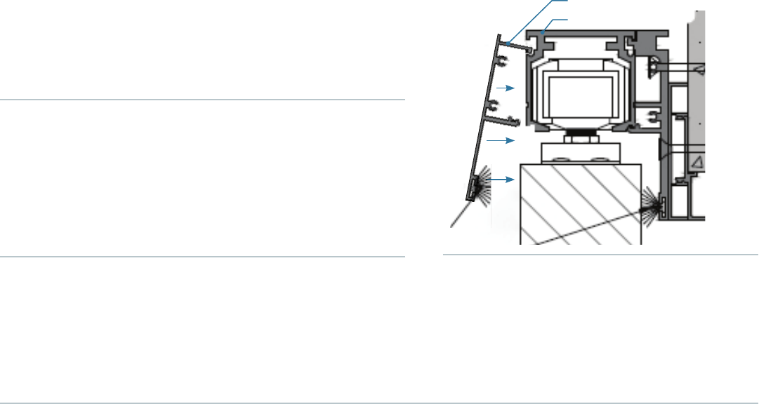
Step 3 Detail
Track
Valance
Backer
B: Predrill and use the provided Backer Screws to secure
the Backer onto the face of the Cased Opening, starting
with the bottom holes. The self-tapping Backer Screws
(Aluminum) are used on the lower part of the Backer.
Use the other Backer Screws (Wood) for the remaining
top holes of the Backer.
C: Slip the Filler Trim behind the section of Backer where
there is a gap between the wall and Backer, flush with
the bottom of Filler Trim and Backer. Drill pilot holes
(3/16”), using the existing holes in the Backer as guides,
through the Filler Trim before attempting to screw in the
Backer Screws.

Step 4: Install Track
Snap in the Track. You may need a rubber mallet to do this. Hold the Track
at a 45-degree angle to the Backer so that the groove at the top of the
Track is positioned to roll into a lip in the Backer (see drawing). Using the
rubber mallet, hit the Track at the top of the face to snap into place. Hitting
the Track at the bottom of the face, or with too much force, will warp it and
may cause the Wheel Sets to malfunction. Start on one end and work your
way to the other.
Installer Note: When putting Track onto Backer, do not hit lower part of track face with
mallet as track will bend.
Installer Note:
• Self-drilling screws are used on lower part of Backer that goes into the cased opening frame only.
• Use wood screws on the remainder of the Backer.
• Have solid side of Filler facing Backer.
• Use shims for top screws of Backer.
• Any gap involving ller should be next to frame.
14 | Step 3-4
Step 3: Install Backer
D: Use the Backer Screws to hold both the Backer and the Filler Trim in place. If the Filler Trim is short, push
it flush with the side opposite of the opening. Do not screw in the top screws until all the bottom ones are
secured. Before tightening the top screws, put 3/8” Backer Shims behind the top of the Backer, next to
each of the screws. This prevents the tightening of the screws from warping the shape of the Backer.
For systems that include an Integrated Backer, skip to step 5.
Backer (Lip)
Track (Groove)
Step 4 Detail NTS

Step 5: Install Receiving Channel
Raise the Receiving Channel up to the bottom of the Backer and shim underneath
if necessary. Hold the pre-drilled Receiving Channel flush with the face of the cased
opening leg/jamb and secure with self-tapping Receiving Channel screws.
Installer Note: Predrill Receiving Channel Holes into Trim prior to installing screws. Serenity logo
indicates top of receiver channel.
Step 5-6 | 15
Step 5 Detail NTS
Step 6: Install Hanger Brackets & Hang Door
A: Hanger bracket holes should be predrilled on the doors from Serenity. Use predrilled
holes to mount brackets. If holes are not predrilled from factory, proceed to Step B.
B: Cut out the “Door Screw Template” located beside the next page (Page 17). Set the door on
the floor along one long edge. Note that the bottom edge of the door has a groove in it.
Starting at one corner that will be an upper corner of the door, measure along the top edge
of the door. Do the same on the opposite end of the top edge for the second Hanger Bracket.
C: Center the Hanger Bracket on your mark. Double-check that the Hanger
Bracket is centered in the 1 3/4” thickness of the door. Use the provided
Hanger Bracket Screws to secure the Hanger Bracket. It is important to note
the handing of the door so that the open face of the Hanger Bracket will face
the cased opening / wall when the door is hung.
Installer Note: Center the Hanger Bracket in the 1 3/4” thickness of the door.
For systems that include a Spring Close, install an extra Hanger Bracket Screw in the
center of the door on the leading edge of the Hanger Bracket. This will be used to hook
the Spring Close cable.
The open face of the Hanger
Bracket needs to face the
Cased Opening/Wall when the
Door is hung.

F: “Reveal” or align the door, adjusting the height of each Hanger Bracket Bolt as
needed. The door needs to be plumb with the Receiving Channel and
centered between the strips of felt at both sides of the channel. Double-check
the bottom clearance: make sure the bottom of the door is not too low or too
high off the floor—1/4” to 3/8” from the floor is optimal. The door needs to
be as low to the ground as possible, with just enough clearance for the Floor
Guide Channel.
Installer Note: Do this step after nished ooring is in place.
Installer Note: The Hanger Bracket can be adjusted to raise or lower the door. Contact Serenity for accommodations if more
adjustments are needed. Before setting door, align soft closes with top of hanger brackets.
Step 6: Install Hanger Brackets & Hang Door
D: Place the adhesive-backed gasketing 1/4” in. along the back edge of door
that faces wall. Be sure the largest fin is closest to the edge of the door. Do
not stretch the gasketing as you place it or it will fall off later.
E: Using the inflatable air shim, lift the door up to the Hanger Bolts and slide the
bolts into the Hanger Bracket.
16 | Step 6

Door Screw Template | 17
Door Screw Template Scale 1"=1"
4 3/4"
11/16"
7/16"
3/8"
11/16"
1/8"
1 3/4"
Door Screw Template
If needed, remove the page to complete Step 6.
Screw preparation to be 1 1/4" deep by 1/8" diameter.
*Prep to be performed on both ends of the door*

Step 7: Position the Floor Guide
A: Mark the floor to position the Floor Guide Channel:
• Begin with the door in the closed position, all the way inside the
Receiving Channel. Mark on the floor at the back edge of the
door (i.e., the end of the door not in the Receiving Channel), just
below the center of the groove visible at the door’s bottom edge.
• Standing behind your mark on the floor, use your laser to shoot a
straight beam along the floor over the dot and into the center of
the Receiving Channel. Trace the 2” of laser line that is right in
front of the jamb/leg trim.
• Swing the door out at an angle to the wall, wedging your
rubber mallet between the door and the jamb/leg trim to hold
the door out of the way.
• Open the door a couple of inches out of the Receiving Channel.
B: Position the Floor Guide Base in the path of the laser lined
up with the beam. Mark the position of the screw holes
on the flooring, then drill with a 1/4” rotohammer drill bit.
Insert the Floor Guide Anchors into the holes.
Installer Note: Skinny Floor Guide Channel with small set screw.
1/4” x 12” rotohammer bit. If using an Automatic Door Bottom, see Step 8:D.
Floor Guide Base
Position this end toward
the front, closer to the
Receiving Channel.
Step 7 | 19

C: Place the base over them with the more horizontal hole
positioned at the front, closer to the receiving channel.
(This will make it easier to make slight adjustments later).
Screw the Floor Guide Base to the floor.
D: Before positioning the Floor Guide Channel, insert the
small Allen screw (set screw) in one end of the channel,
as shown. Screw it in with a 2 mm Allen wrench until the
outside of the screw is flush with the edge of the guide.
This makes the guide slightly wider so the door won’t have
too much play.
E: Remove the mallet that was wedged in at the center of
the door to hold the door out at an angle.
F: Slide the door closed, then slide the Floor Guide Channel
into place over the Floor Guide Base. Position the Channel
with the Allen/set screw facing toward the back of door.
Floor Guide Channel
with Allen screw in place.
Step 7: Position the Floor Guide
20 | Step 7

Step 8: Install Auto Door Bottom
For systems that include an Automatic Door Bottom, proceed to step 8. If your
system is not configured to include this part for sound attenuation, skip to step 9.
A: Insert the seal noting the handing of the door. The drop seal should face the inside of the
room with the floor guide channel towards the corridor.
B: Fix the angle bracket. Mark and drill pilot hole.
A A
B B
Trailing
Edge
Inside Room Hallway
Closing
Edge
Step 8 | 21

= 1 5/16 in. + B
Y
Y
Y
1 5/16 in.
4.72 in.
B
B1 5/16 in.
C: Push floor guide to trigger drop seal. Mark position of floor guide.
Installer Note: Diagram is not exact.
Inside Room
22 | Step 8

Installer Note: Predrill with 1/8” Rotohammer Bit.
D: Screw floor guide base.
1
1
2
2
4 x 1 in.
4 x 1 in.
Step 8 | 23

8
E
B
E
E
E
E
C
A
1.
2.
1/2 - 5/8 in.
Trigger Height Options
3/8 - 1/2 in.
1/4 - 3/8 in.
E: Push appropriate trigger B into floor plate C. See floor
gap E to avoid pressure on floor. Hang door and check
operation. If dragging, change trigger by again removing
bracket A.
Installer Note: “E” represents the door height off of the oor.
24 | Step 8
Step 9: Install Valance
Step 10: Install Receiving
Channel Cover
Step 11: Install Handles,
Endcaps, and Labels
Hold the Valance at a 45-degree angle to the Track so that
the lip of the Valance is positioned to roll into a groove on the
Track, as shown. Snap the Valance onto the Track.
Snap on the Receiving Channel Cover. Use a mallet to tap
it into position. Make sure the Receiving Channel and the
Receiving Channel Cover are even at the top.
A: Install the door pull or back to back ladder handle.
Installer Note: Make sure the set screws are facing the oor.
Installer Note: Have door in open position when installing. When
snapping on, hit the middle of the Valance.
Installer Note: For systems that include a Spring Close, once door is hung and operating, hook Spring Close cable
around Hanger Screw from Step 5:C. Ensure operation of Spring Close and adjust tension as needed.
Step 9 Detail NTS
Valance
Track (Groove)
Step 9-11 | 25

C: If the door has locking hardware you may need to drill
the face prep on the door. Install the lock into the door
and extend the bolt. Line up the strike plate with the
Receiving Channel strike prep and mark its correct
position in relation to the bolt. Mark the strike prep holes
then drill them with a 1/8” drill bit. Using the strike screws
that we provided secure the strike plate & dust box to
the Receiving Channel and verify that the lock engages.
Follow instructions for locks provided. Check submittal
for location and application.
13 3/8”
3mm
Step 12: Verify Stop and Trigger
Close door until it barely touches the Receiving Channel.
It should measure 13 3/8” from the edge of the Stop to
the edge of the Trigger. This is a critical measurement to
ensure proper functioning of the Soft Close Assembly.
Overextension of the Soft Close Assembly can cause it
to fail. Make final adjustments if necessary.
Step 12 Detail NTS
Close Side: Verify the rollers are touching the stop
when the door is fully closed - then verify trigger
distance.
Open Side: Verify Door hangs into opening 4 1/2” - 5”
when the rollers are touching the stop - then verify
trigger distance.
B: Screw Endcaps onto both ends of the track system securing the Backer to
Valance. The Endcaps should be flush.
The Endcap should be tight to the side of the cased opening, with no gap,
and flush with the bottom of the Header.
26 | Step 11-12
Installer Note: Install by hand with a #2 Phillips screwdriver.
Endcaps (Stnd/Sloped)
We’re here to support your project. Please refer to the first page of the
manual for contact information and how-to videos.
Need Help with Your Install?
You have successfully installed the Serenity Sliding Door Systems®
Surface
Mount
System. No additional steps are required.
The system install is complete.

SerenitySlidingDoor.com
