
Night Vision Systems
WWW.SERFAS.COM
TOLL FREE: (800)424-0047
SERFAS, INC. 2333 W. Utopia Rd. Phoenix, AZ 85027

USER GUIDELINE
Thank you for choosing a Serfas True series headlight!
* For using this product safely, conveniently and keeping it well-preserved, please read this manual carefully before using.
Please keep this manual for future reference.
CONTENTS
CONTENTS INCLUDED & SPECIFICATION
1
HEAT SINK AND COOLING SYSTEM
2
MOUNTING THE HEADLIGHT
3 - 4
LIGHT OPERATION
5 - 6
REMOTE SWITCH OPERATION
7
BAT-4 BATTERY OPERATION
8 - 9
BATTERY MOUNTING
10
RUN TIME & LIGHT DIAGRAM
11
TROUBLESHOOTING
12
WARRANTY & CARE
12
Do Not Dispose
of in Trash

SPECIFICATIONS
TSL-2500
* High Performance Cree LEDs
* Alloy / Nylon Body
* Precision Optical Lens
* Ram Air Venting for Cooler Operating Temperatures
* 4 modes : Over Drive / High / Standard / Low
* Over Heat Protection System
* Low Battery Indicator
* Port for TL-80 Tail Light Option
BAT-4
* Rechargeable Lithium Ion Battery (7.4V 6600mAh)
* Low Battery Indicator
* USB Power Port for Accessory Charging
* TSL-2500 Head
* Rechargeable Battery Pack
6600mAh (BAT-4)
* Wall Charger (S-TSL-CHARGER)
* Wired Remote Switch (S-TRIGGER)
* 3 Foot Extension Cable (S-EXT-2)
* 1 Foot Extension Cable (S-EXT-3)
* Serfas Handle Bar Bracket (S-UNIHEAD)
* Serfas Helmet Bracket (S-UNIHELMET)
* Manual
* Carrying Case
* Battery Strap (S-STRAP-BAT)
CONTENTS INCLUDED
BAT-4
TSL-2500
S-EXT-2
S-UNIHEAD
S-UNIHELMET
S-TRIGGER
S-STRAP-BAT
S-TSLCHARGER S-EXT-3
TL-80
Not Included
HEAT SINK AND COOLING SYSTEM
The high powered output of the TSL-2500 creates a
lot of heat. The cooler the LED’s run they will have a
longer lifetime. Your light will also produce more light.
To reduce the heat generated by the running LEDs, the
TSL-2500 was designed with an aluminum alloy body
and equipped with Serfas’ Ram Air cooling system.
The Ram Air cooling system lets air flow through the
light body when riding.
As a precaution, do not run light while bike is
stationary. To properly cool the unit, it must
have airflow.
Copper plate LED board
increases the LED heat
transfer rate and enhances
the light’s performance.
01 02
BACK VIEW
FRONT VIEW
Aluminum heat sink
Ram-Air vent system
CONTENTS HEAT SINK AND COOLING

03
04
INSTALL
click
RELEASE
PRESS
HANDLEBAR MOUNTING HELMET MOUNTING
To adjust the horizontal beam, spin the headlight
left to right for your best side to side beam angle.
To adjust the vertical beam angle, loosen the
mounting and rotate the light up and down to
your best vertical beam angle, then tighten
the mounting.
UNIVERSAL BRACKET INSTRUCTIONS:
Open bracket by pulling thumb lever down, then unclip the
thumb lever from the cam hook to open. Adjust the rubber
strap length to fit bar by moving the strap up or down the
rungs located under the swivel light mount. Once the length
of strap is adjusted for best fit, install around handle bar or
seat post by inserting thumb lever into cam hook, then
rotate thumb lever upwards towards swivel mount to lock.
If light still moves on the bar open thumb lever and shorten
strap by moving the rubber strap up to the next rung.
THUMB
LEVER
RUBBER
HORIZONTAL
TENSION
SCREW
RELEASE
LEVER
RUNGS
HELMET BRACKET INSTRUCTIONS:
1. Remove hook and loop strap from one side of the helmet mount.
2. Put helmet mount in desired location on helmet (top center works best).
3. Insert strap through nearest air vent on top of helmet and loop around
inside of top of helmet to the next closest vent to the open strap hole on the
helmet mount.
4. Put hook and loop strap through open hole on helmet mount and pull snug
and attach hook and loop to itself.
05 06
HEAD LIGHT OPERATION OVERHEAT PROTECTION
POWER BUTTON
3. Press and hold the on / off button around 1 second to turn
off the light.
4. When the indicator on the power button goes from solid blue
to blinking red the battery has 20% or less charge remaining.
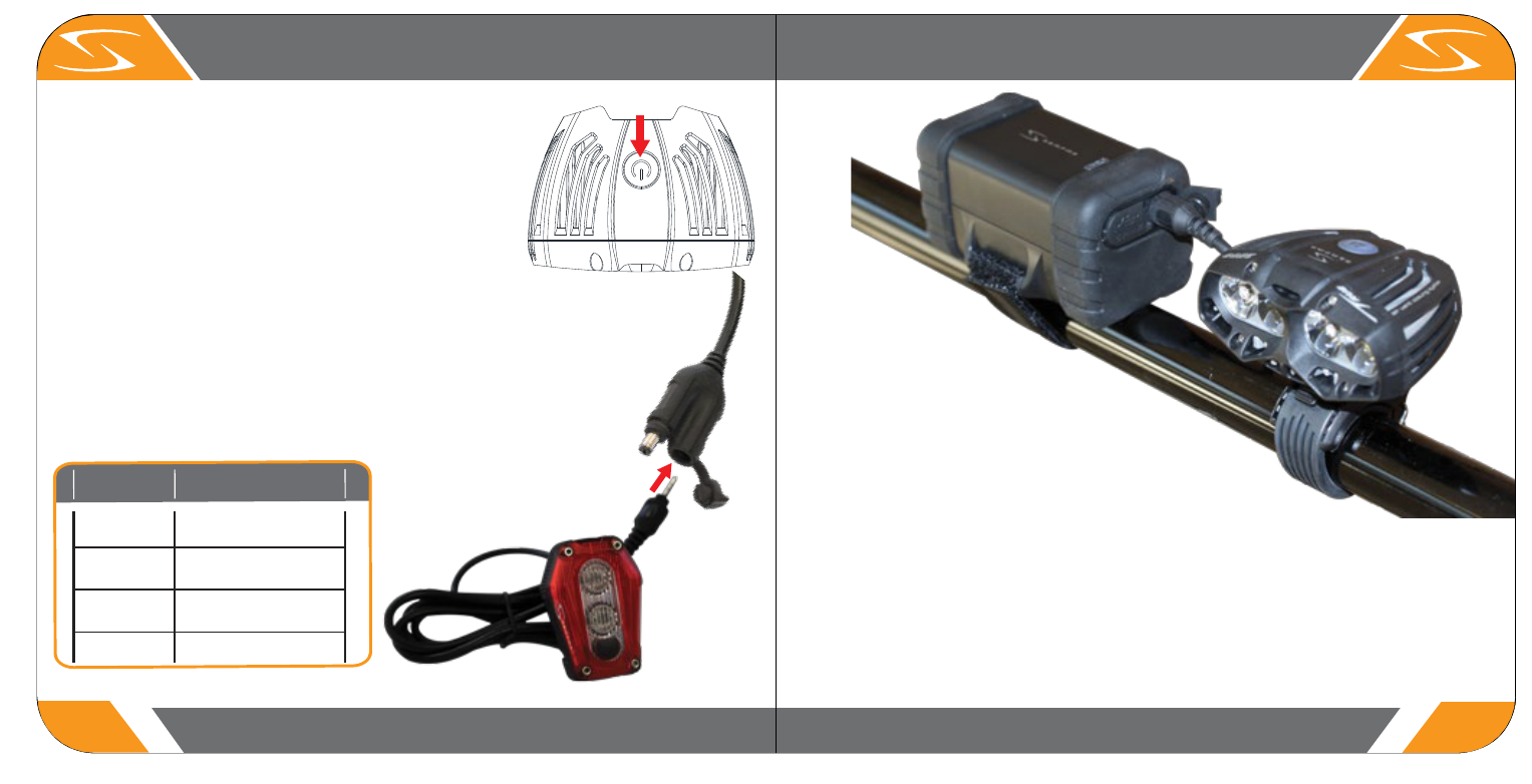
OPTIONAL TL-80 TAIL LIGHT OPERATION (SOLD SEPARATELY)
1. Your new light has four brightness settings (over drive,
high, medium and low). Simply press the power button to
turn on.
1. Plug connector from tail light into connector A on figure 1.
2. When plugged in the TL-80 functions based off of the setting of the head light.
3. Off switch on TL-80 is only used to turn tail light on or off.
The overheat protection circuitry in your light ensures that
it operates at safe temperatures to insure a long life.
Continued heat build up is the biggest enemy of LED’s and
causes lower lumen output and lifespan when operated too
hot. Under proper operating conditions your LED should
last 50,000+ hours. (See battery info for battery lifespan)
When your light is on many factors can cause it to get too
hot (inadequate airflow, mud, dirt, walking up that hill).
When this happens the circuitry in this device will
automatically go into “Standard” mode. Once the air flow
over the light has improved and the running temperature is
reduced the circuitry will kick the light back into the
previous mode.
2. With each additional press of the power button the light will cycle
through its modes.
TL-80
Not Included
Figure 1
Connector A
Off Button
Front
Tail
Overdrive
Steady
Steady
High
Flash
Medium
Alternating ash
Low
Modes

07 08
REMOTE SWITCH BAT-4 BATTERY OPERATION
It is normal that the battery may reach high temperatures during charging (up to 104°F/40°C), as there
is a chemical reaction happening in the battery.
Several factors can influence the battery’s durability and lifespan: type of cell strain, the maintenance
routine, the temperature and etc.
The battery capacity may become less effective; having about 80% of its capacity after 300-500
charge/discharge cycles. The battery may have 3 years or more life span under good care.
The battery voltage and capacity decrease at low temperatures, especially near or below freezing point.
The capacity decreases 5% - 10% at freezing. Around 0°F, the capacity decreases 30%. The battery
performance will return normal when the temperature gets to 70°F/20°C.
The battery will lose around 1% of its capacity per day when you store the battery at normal room
temperature. Battery temperature should never exceed 104°F/40°C, it will lose about 5% of its capacity
per day.
Fully charge the battery before storing. When not in use, we suggest a cool and dry place for storage.
Li-Ion batteries are volatile. Failure to read or follow the instructions may result in fire, personal injury or
damage to property. Do not leave batteries unattended during charging or use. Dispose of battery pack
properly if there is any noticeable damage to casing.
Equipped with a remote switch, allows you easier
on the fly control of your light. You can mount the
switch close to the grip area of your bars so that
your hands don't have to leave the bar to change
settings. It is also mountable on your helmet for
easier to reach control.
1. Open the rubber cap on the back of the light.
2. Then plug in the controller wire.
3. Make sure it has been completely connected.
1. Put one of the ends of the hook and loop strap
around the handle bar.
2. Align to the controller button and pass through
open eyelet on switch base.
3. Pull the hook and loop ends tightly.
1. Put one end of the belt go through the helmet hole.
2. Align to the controller button and pass through.
3. Pull the hook and loop ends tightly.
* When unused, please ensure the protective cap
is closed to avoid water getting in the light body.
REMOTE SWITCH OPERATION (Fig. 1)
REMOTE SWITCH MOUNTING (Fig. 2)
REMOTE SWITCH HELMET MOUNTING
Fig. 1
Fig. 2
INPUT : 8.4VDC 1.5A
RATING : 7.4V 6600mAh
48.84 Whr
RATING : 3.7V 13200mAh
OUTPUT : 5.0VDC 1A

BATTERY CONNECTION
1. USB Port
2. Charging Port
3. Low Battery Indicator
BATTERY OPERATION
09 10
BAT-4 BATTERY OPERATION BAT-4 BATTERY MOUNTING
1.2.
3.
1. Thread the hook and loop strap counterclockwise through the 2 slots at the side of the battery.
The hook surface of the hook and loop strap should face the battery.
2. Place the battery on the frame where it is safe and convenient.
3. Wrap the hook and loop strap over the tube.
4. Thread the hook and loop strap through the slot on the top end of the strap itself.
5. Pull the hook and loop strap and attach it tightly and firmly.
MOUNTING THE BATTERY
1. Plug S-EXT-3 or S-EXT-2 cable into charging port. Then plug into cable connected to TSL-2500 head.
2. To charge accessory using USB port, simply plug into USB port (1.).
* Make sure the cover is closed, when not in use.
* Battery will automatically stop charging when full charge is achieved.
Remove battery from charger and reinsert rubber pull tab into USB port to keep out water and dirt.
Charging
1. Carefully open rubber dust cover on top side of battery, exposing charging port.
2. Insert charging cord into charging port.
3. Plug supplied wall charger into wall outlet.
4. Charge indicator on charger will turn red when
charging and solid green when fully charged.
* Do not leave battery unattended while plugged into charger or while in use.
Low Battery Indicator
1. When the battery capacity is down to the supply limit, the Low Battery Indicator will blink red.
Charging Indicator

11 12
RUN TIME & LIGHT DIAGRAM
Serfas warrants to the original purchaser of this product that the
product is free from defects in material and workmanship for the
lifetime of the product. This warranty does not apply to damage due
to heat, physical damage (crashing) resulting from abuse, neglect,
improper repair, improper fit, or alterations of the fixture. This warranty
is in lieu of all other agreements and warranties, general or specific,
express or implied and no representative or person is authorized to
assume liability on behalf of Serfas in connection with the sale and use
of this product.
Serfas reserves the right to request the return of any product
submitted for warranty consideration. All customers should contact
Serfas directly for warranty service.
To make a claim, please e-mail [email protected].
* Please include your full contact information (name, address, phone
number, and e-mail [if applicable]), and a description of the issue.
* Address items to:
Serfas
2333 W. Utopia Rd.
Phoenix, AZ 85027
Serfas batteries are covered by a ONE YEAR LIMITED WARRANTY
from the date of purchase. This covers the battery and battery internal.
For more information please contact us at [email protected].
International consumers please contact your local distributor,
complete list distributors can be found at:
https://www.serfas.com/sitepages/view/8
Please file claims with Serfas directly.
Do not take to retailer for warranty issues.
1. Problem: The headlight does not power up.
* Make sure the power button was firmly pressed.
* Make sure battery is securely connected with the headlight.
* Make sure the battery is fully charged.
2. Problem: The tail light does not power up.
* Make sure it is properly plug in.
* Make sure button on TL-80 is not in off position.
TROUBLESHOOTING
WARRANTY
CARE
!
* Make sure to clean the dust and dirt on the light with soft damp cloth
after every ride.
* Water resistant is for rain water only. Do not submerge the battery or
the whole light into water when cleaning.
When riding at night, please follow the guidelines below:
* Use caution when handing, the light may get hot.
* Unplug the battery and headlight if not in use.
* Unplug the battery and charger if not in use.
* Unplug connector by the plug end, never by pulling on
the cable.
* Do not amend or replace any parts with Non-Serfas
parts.
* Do not dismantle the headlight or battery case.
* Provide sufficient airflow to the headlight for cooling
during use.
* Do not use submerged under water.
* Do not look directly at light.
* Do not leave the light on and unattended.
* Keep headlight and battery away from fire and
combustible materials.
* Do not store head unit when hot or straightway after use.
* Unplug the USB cable when fully charged.
* This light is for bicycle use only.
TSL-2500 with TL-80 light runtimes
Overdrive
Steady
Steady
High
Flash
Medium
Alternating ash
1:30
2:30
3:45
6:45
Low
Mode 1
Mode 2
Mode 3
Mode 4
TSL-2500 Runtimes (Headlight Only)
Lumens
Mode
Tail
Overdrive
High
2500
None
None
1600
Medium
None
1000
Low
None
1:45
2:45
4:00
7:30
600
Runtime [hrs:min]
Front
Mode
Tail
Runtime [hrs:min]
