
XAS 185 KD7 T4
Instruction Manual
for AC Compressors
English
Engine Kubota V2403

ATLAS COPCO - PORTABLE ENERGY DIVISION
www.atlascopco.com
Printed matter Nr
1310 3013 85
09/2014
Instruction Manual for AC Compressor
XAS 185 KD7 T4
Original instructions

- 4 -
Warranty and Liability Limitation
Use only authorized parts.
Any damage or malfunction caused by the use of unauthorized parts is not covered by Warranty or Product Liability.
The manufacturer does not accept any liability for any damage arising from modifications, additions or conversions made without the manufacturer's approval in
writing.
Neglecting maintenance or making changes to the setup of the machine can result in major hazards, including fire risk.
While every effort has been made to ensure that the information in this manual is correct, Atlas Copco does not assume responsibility for possible errors.
Copyright 2014, Atlas Copco.
Any unauthorized use or copying of the contents or any part thereof is prohibited.
This applies in particular to trademarks, model denominations, part numbers and drawings.

- 5 -
Preface
Please read the following instructions carefully before
starting to use your compressor.
It is a solid, safe and reliable machine, built according to
the latest technology. Follow the instructions in this
booklet and we guarantee you years of troublefree
operation.
Always keep the manual available near the machine.
In all correspondence always mention the compressor
type and serial number, shown on the data plate.
The company reserves the right to make changes without
prior notice.
Table of contents
1 Safety precautions for portable
compressor ...................................................7
1.1 Introduction ........................................................7
1.2 General safety precautions .................................7
1.3 Safety during use and operation .........................8
1.4 Safety during maintenance and repair ................9
1.5 Tool applications safety ......................................9
1.6 Batteries ..............................................................9
1.7 Ether fuel Systems ............................................10
1.8 Pressure vessels ................................................10
1.9 Safety valves .....................................................10
1.10 Injury Prevention ..............................................10
2 Leading particulars ....................................12
2.1 Description of Safety Pictograms Used in this
Manual ..............................................................12
2.2 General description ...........................................12
2.3 Main Parts .........................................................14
2.4 Air flow ............................................................18
2.5 Oil system .........................................................18
2.6 Continuous regulating system ..........................18
2.7 Electric system ..................................................20
2.7.1 Circuit Diagram................................................. 20
3 Operating instructions ...............................22
3.1 Parking, towing and lifting instructions ...........22
3.1.1 Drawbar Preparations for Towing .................... 22
3.2 StartiNg / Stopping ...........................................23
3.2.1 Overview Icons ................................................. 24
3.2.2 Starting ............................................................. 27
3.2.3 Stopping ............................................................ 31
3.2.4 Shutdown .......................................................... 32
3.2.5 Power Off ......................................................... 32
3.2.6 Diesel Particulate Filter regeneration ............... 32
3.2.7 Automatic Dpf Regeneration (Default) ............ 33
3.2.8 Inhibit Dpf Regeneration .................................. 33
3.2.9 Increasing Soot Load ........................................ 33
3.2.10 Turning Regeneration Back To
Auto ...................................................................34
3.2.11 Force Dpf Regeneration ....................................34
3.2.12 Service Regeneration .........................................34
3.2.13 Settings ..............................................................34
3.2.14 Fault Codes ........................................................36
3.2.15 Emergency Stop ................................................39
3.2.16 Parking Instructions ...........................................40
3.2.17 Towing Instructions ...........................................40
3.2.18 Lifting Instructions ............................................40
3.3 Before Starting ..................................................40
4 Maintenance ..............................................41
4.1 Use Of Service Paks .........................................41
4.2 Preventive Maintenance Schedule For The
Compressor .......................................................41
5 Technical Specifications ...........................42
5.1 Reference Conditions .......................................42
5.2 Limitations ........................................................42
5.3 Altitude Unit Performance
Curve ................................................................43
5.4 Performance Data .............................................44
5.5 Design Data ......................................................44
5.5.1 Compressor ........................................................44
5.5.2 Engine ................................................................44
5.5.3 Unit ....................................................................44
5.6 Lubrication Oils ................................................46
5.6.1 Check Engine Oil Level ....................................47
5.6.2 Check Compressor Oil Level ............................47
5.6.3 Engine Oil And Oil Filter Change .....................47
5.6.4 Compressor Oil And Oil Filter Change .............47
5.7 Cleaning Coolers ..............................................48
5.8 Battery Care ......................................................48
5.8.1 Electrolyte .........................................................48
5.8.2 Recharging A Battery ........................................48
5.8.3 Battery Maintenance .........................................48
5.9 Storage ..............................................................48
5.10 Service Kits ......................................................48

- 6 -
6 Adjustments And Servicing Procedures ... 49
6.1 Adjustment Of The Continuous Regulating
System ..............................................................49
6.2 Air Filter Engine/compressor ...........................50
6.2.1 Main Parts .........................................................50
6.2.2 Cleaning The Dust Trap ....................................50
6.2.3 Replacing The Air Filter Element .....................50
6.3 Air Receiver ......................................................51
6.4 Safety Valve .....................................................51
6.5 Fuel System ......................................................51
7 Problem Solving ....................................... 52
7.1 Problem Solving Chart .....................................52
7.2 Alternator Precautions ......................................52
8 Maintenance Log ...................................... 54
9 Maintenance Log ...................................... 55

- 7 -
Safety precautions for portable compressor
Introduction
The policy of Atlas Copco is to provide the users of their
equipment with safe, reliable and efficient products.
Factors taken into account are among others:
- the intended and predictable future use of the products, and
the environments in which they are expected to operate,
- applicable rules, codes and regulations,
- the expected useful product life, assuming proper service and
maintenance,
Before handling any product, take time to read the
relevant instruction manual. Besides giving detailed
operating instructions, it also gives specific information
about safety, preventive maintenance, etc.
These precautions are general and some statements will
therefore not always apply to a particular unit.
When handling, operating, overhauling and/or
performing maintenance or repair on Atlas Copco
equipment, the mechanics are expected to use safe
engineering practices and to observe all relevant local
safety requirements and ordinances. The following list is
a reminder of special safety directives and precautions
mainly applicable to Atlas Copco equipment.
This brochure applies to machinery processing or
consuming air. Processing of any other gas requires
additional safety precautions typical to the application
and are not included herein.
All responsibility for any damage or injury resulting from
neglecting these precautions or by non-observance of
ordinary caution and due care required in handling,
operating, maintenance or repair, also if not expressly
mentioned in this instruction manual, is disclaimed by
Atlas Copco.
If any statement does not comply with local legislation,
the stricter of the two shall be applied. Statements in this
manual should not be interpreted as suggestions,
recommendations or inducements that it should be used in
violation of any applicable laws or regulations.
General safety precautions
1 The owner is responsible for maintaining the unit in a
safe operating condition. Unit parts and accessories
must be replaced if missing or unsuitable for safe
operation.
2 Use only lubricating oils and greases recommended or
approved by Atlas Copco or the machine manufacturer.
Ascertain that the selected lubricants comply with all
applicable safety regulations, especially with regard to
explosion or fire risk and the possibility of
decomposition or generation of hazardous gases.
3 The supervisor, or the responsible person, shall at all
times make sure that all instructions regarding
machinery and equipment operation and maintenance
are strictly followed and that the machines with all
accessories and safety devices, as well as the
consuming devices, are in good repair, free of
abnormal wear or abuse, and are not tampered with.
4 Maintenance, overhaul and repair work shall only be
carried out by adequately trained personnel; if
required, under supervision of someone qualified for
the job.
5 Whenever there is an indication or any suspicion that
an internal part of a machine is overheated, the
machine shall be stopped but no inspection covers shall
be opened before sufficient cooling time has elapsed;
this to avoid the risk of spontaneous ignition of oil
vapour when air is admitted.
6 Maintenance work, other than routine attention, shall
only be undertaken when the machine is turned off.
7 Before dismantling any pressurized component, the
compressor or the equipment shall be effectively
isolated from all sources of pressure and be completely
vented to atmosphere. In addition, a warning sign
bearing a legend such as "work in progress; do not
open" shall be attached to each of the isolating valves.
8 Before a machine is being repaired, steps shall be taken
to prevent inadvertent starting. In addition, a warning
sign bearing a legend such as "work in progress; do not
start" shall be attached to the starting equipment. The
battery shall be disconnected and removed or the
terminals covered by insulating caps.
9 Normal ratings (pressures, temperatures, speeds, etc.)
shall be durably marked.
10 Never operate a machine or equipment beyond its rated
limits (pressure, temperature, speed, etc.).
11 Maintenance and repair work should be recorded in an
operator's logbook for all machinery. Frequency and
nature of repairs can reveal unsafe conditions.
12 The machinery and pneumatic equipment shall be kept
clean, i.e. as free as possible from oil, dust or other
deposits.
13 To prevent an increase in working temperature, inspect
and clean heat transfer surfaces (cooler fins,
intercoolers, water jackets, etc.) regularly. For every
machine establish a suitable time interval for cleaning
operations.
14 All regulating and safety devices shall be maintained
with due care to ensure that they function properly.
They may not be bypassed.
15 Care shall be taken to avoid damage to safety valves
and other pressure relief devices, especially to avoid
plugging by paint, oil coke or dirt accumulation, which
could interfere with the functioning of the device.
16 Pressure and temperature gauges shall be checked
regularly with regard to their accuracy. They shall be
replaced whenever outside acceptable tolerances.
17 Parts shall only be replaced by genuine Atlas Copco
replacement parts.
18 Safety devices shall be tested as described in the
maintenance schedule of the instruction book(s) to
determine that they are in good operating condition.
19 Never use flammable solvents or carbon tetrachloride
for cleaning parts. Take safety precautions against
toxic vapors when cleaning parts in or with cleaning
products.
20 Observe scrupulous cleanliness during maintenance
and repair. Keep away dirt by covering the parts and
exposed openings with clean cloth, paper or tape.
21 Protect the engine, alternator, air intake filter, electrical
and regulating components, etc. to prevent moisture
ingress, e.g. when steam-cleaning.
To be read attentively and acted accordingly before towing, lifting, operating, performing maintenance
or repairing the compressor.

- 8 -
22 When performing any operation involving heat, flames
or sparks on a machine, the surrounding components
shall first be screened with non-flammable material.
23 Never use a light source with open flame for inspecting
the interior of a machine, pressure vessel, etc.
24 On portable units, support the drawbar and axle(s)
securely if working underneath the units or when
removing a wheel. Do not rely on jacks.
25 Prior to stripping a compressor, engine or other
machine or undertaking major overhaul on it, prevent
all movable parts with a mass exceeding 15 kg (30 lbs)
from rolling over or moving.
26 When repair has been completed, make sure that no
tools, loose parts or rags are left in, or on, the machine,
the prime mover or the driving gear. The machine shall
be barred several revolutions to ensure that there is no
mechanical interference within the machine or driver.
Safety during use and operation
To lift a unit, all loose or pivoting parts, e.g. doors shall
first be securely fastened. Do not attach cables, chains or
ropes directly to the lifting eye; apply a crane hook or
lifting shackle meeting local safety rules.
Helicopter lifting using the lifting eye is forbidden.
It is strictly forbidden to dwell or stay in the risk zone
under a lifted load. Never lift the unit over people or
residential areas.
Lifting acceleration and retardation shall be kept within
safe limits.
1 Before towing the unit:
- ascertain that the pressure vessel is depressurized,
- check the drawbar, the brake system and the towing eye. Also
check the coupling of the towing vehicle,
- check that the pivot wheel or stand leg is safely locked in the
raised position,
- ascertain that the towing eye can swivel freely on the hook,
- check that the wheels are secure and that the tires are in good
condition and inflated correctly,
- connect the signal cable, check all lights and connect the
pneumatic brake couplers,
- attach the safety break-away cable to the towing vehicle,
- remove wheel chocks, if applied, and disengage the parking
brake.
- Apply safety chains to tow vehicle.
2 If the unit is to be backed up by the towing vehicle,
disengage the overrun brake mechanism (if equipped).
3 Never exceed the maximum towing speed of the unit.
4 Place the unit on level ground and chock the wheels
before disconnecting the unit from the towing vehicle.
Unclip the safety break-away cable
5 When the unit has to operate in a fire-hazardous
environment, each engine exhaust has to be provided
with a spark arrestor to trap incendiary sparks.
6 The exhaust contains carbon monoxide which is a
lethal gas. When the unit is used in a confined space,
conduct the engine exhaust to the outside atmosphere
by a pipe of sufficient diameter (min. 4 inches); do this
in such a way that no extra back pressure is created for
the engine. If necessary, install an extractor.
7 When operating in a dust-laden atmosphere, place the
unit so that dust is not carried towards it by the wind.
Operation in clean surroundings considerably extends
the intervals for cleaning the air intake filters and the
cores of the coolers.
8 Locate the unit away from walls. Take all precautions
to ensure that hot air exhausted from the engine and
driven machine cooling systems cannot be
recirculated. If such hot air is taken in by the engine or
driven machine cooling fan, this may cause
overheating of the unit; if taken in for combustion, the
engine power will be reduced.
9 No external force may be exerted on the air outlet
valves, e.g. by pulling on hoses or by installing
auxiliary equipment directly to a valve, e.g. a water
separator, a lubricator, etc.
10 Distribution pipework and air hoses must be of correct
size and suitable for the working pressure. Never use
frayed, damaged or deteriorated hoses. Replace hoses
and flexibles of which the lifetime expired. Use only
the correct type and size of hose end fittings and
connections. Install safety pins on quick type hose
connections. A hose connected to a 2 inch (50 mm)
valve must be provided with a safety wire (8 mm) fixed
to the hose for effective pressures as from 145 psi (10
bar) up, although it is recommended to apply such
safeguard already from (60 psi) 4 bar up.
The safety wire ends have to be attached, one to the eye
provided next to the compressor air outlet valve, the
other one to a point near to the air inlet of the applied
equipment. Finally a wire mesh hose can be fixed over
the hose ends to dampen the blast in case a connection
starts leaking or should become undone.
Close the compressor air outlet valve before
connecting or disconnecting a hose. Ascertain that a
hose is fully depressurized before disconnecting it.
When blowing through a hose or air line, ensure that
the open end is held securely. A free end will whip and
may cause injury.
Never play with compressed air. Never apply it to your
skin or direct an air stream at people. Never use it to
clean dirt from your clothes. When using it to clean
down equipment, do so with extreme caution and use
eye protection.
11 Never move a unit when external lines or hoses are
connected to the outlet valves, to avoid damage to
valves and/or manifold and hoses.
12 Never refill fuel while the unit is running. Keep fuel
away from hot parts such as air outlet pipes or the
engine exhaust. Do not smoke when fueling. When
fueling from an automatic pump, a ground cable should
be connected to the unit to discharge static electricity.
Never spill nor leave oil, fuel, coolant or cleansing
agent in or around the unit.
13 Never operate the unit in surroundings where there is a
possibility of taking in flammable or toxic fumes.
14 1Never operate the unit at pressures or speeds below or
in excess of the limit ratings stated on the Principal
Data sheet.
15 On water-cooled engines with closed cooling circuit:
allow the unit to cool before removing a pressure cap.
16 All doors shall be shut during operation so as not to
disturb the cooling air flow inside the body-work and/
or render the silencing less effective. A door should be
kept open for a short period only, e.g. for inspection or
adjustment
17 Wear ear protectors when environmental noise can
reach or exceed 85 dB(A). Beware of long-time
exposure to noise.
18 Periodically check that:
- all safety equipment is in good working order,
- all guards and air conducting baffles are in place and securely
fastened,

- 9 -
- all hoses and/or pipes inside the unit are in good condition,
secure and not rubbing,
- there are no fuel, oil or coolant leaks,- all fasteners are tight
- all electrical leads are secure and in good order,
- the engine exhaust system is in good condition,
- air outlet valves and manifold, hoses, couplings, etc. are in good
repair, free of wear or abuse,
- the wheel nuts are tightened to the proper torque.
When more than one compressor is connected to a common
header, be sure each compressor has a non-return valve
(check valve) to prevent reverse rotation when stopping.
Safety during maintenance and repair
Maintenance, overhaul and repair work shall only be
carried out by adequately trained personnel; if required,
under supervision of someone qualified for the job.
1 Use only the correct tools for maintenance and repair
work, and only tools which are in good condition.
2 Parts shall only be replaced by genuine spare parts.
3 All maintenance work, other than routine attention,
shall only be undertaken when the unit is stopped.
Ensure that the unit cannot be started inadvertently
4 Before removing any pressurized component, the
compressor or equipment shall be effectively isolated
from all sources of pressure and the entire system shall
be relieved of pressure. Do not rely on non-return
valves (check valves) to isolate pressure systems.
5 Never use flammable solvents for cleaning (fire-risk).
Take safety precautions against toxic vapours of
cleaning liquids.
6 Scrupulously observe cleanliness during maintenance
and when performing repairs. Keep dirt away by
covering the parts and exposed openings with a clean
cloth, paper or tape.
7 Never weld on or perform any operation involving heat
near the fuel or oil systems. Fuel and oil tanks must be
completely purged, e.g. by steam-cleaning, before
carrying out such operations. Never weld on, or in any
way modify, pressure vessels. Disconnect the
alternator cables during arc welding on the unit.
8 Support the drawbar and the axle securely if working
underneath the unit or when removing a wheel. Do not
rely on jacks.
9 Make sure that no tools, loose parts or rags are left in
or on the unit.
10 Before clearing the unit for use after maintenance or
overhaul, check that operating pressures, temperatures
and speeds are correct and that the control and
shutdown devices function correctly.
11 Do not remove any of, or tamper with, the sound
damping material. Keep the material free of dirt and
liquids such as fuel, oil and cleansing agents.
12 Protect the electrical and regulating components, the
air filter, etc. to prevent moisture from entering them,
e.g. when steamcleaning.
Tool applications safety
Apply the proper tool for each job. With the knowledge of
correct tool use and knowing the limitations of tools,
along with some common sense, many accidents can be
prevented.
Special service tools are available for specific jobs and
should be used when recommended. The use of these
tools will save time and prevent damage to parts.
1 Use only wrenches or sockets whose size fits the
fastener.
2 Apply an open-end wrench only in the place of the
fastener head, square to the thread axis.
3 Do not use a pipe or other improvised leverage
extensions on handles.
4 Do not hammer on wrenches or other tools which are
not specially designed for it.
5 Always support the ratchet head when using socket
extensions.
6 Discard any wrench with broken or battered points or
edges.
7 Never use hand type sockets on power or impact tools.
8 Select only heavy-duty impact sockets for use with
pneumatic or electric impact tools.
9 Replace sockets showing cracks or wear; keep sockets
clean.
10 Never use screwdrivers for prying, punching,
chiseling, scoring or scraping.
11 Use the correct type and size of screwdriver for the job.
The bit must match the fastener.
12 A screwdriver with rounded edges will slip; it needs to
be redressed or discarded.
13 Never use a screwdriver or any other tool near a live
wire or electrical component. Plastic covering of
handles is for comfort and grip only. They are not
intended to act as insulation if such is not clearly
marked by the manufacturer.
14 Never strike a hammer against a hardened object; use a
soft drift against the object and strike against the drift.
15 Strike the object with the full face of the hammer.
16 Never use a hammer with a loose head.
17 Discard a hammer with chipped or mushroomed face.
18 Never use a chisel or punch with a chipped or
mushroomed striking face.
19 Always pull on a wrench or socket handle, if possible,
and adjust your stance to prevent a fall if something lets
go.
20 Wear approved eye protection when using percussion
tools or when scraping, chipping, shaving or grinding.
21 Wear protective gloves when holding a chisel or punch.
Batteries
When servicing batteries, always wear protecting
clothing and glasses.
1 The electrolyte in batteries is a sulphuric acid solution
which is fatal if it hits your eyes, and which can cause
burns if it contacts your skin. Therefore, be careful
when handling batteries, e.g. when checking the charge
condition.
2 Install a sign prohibiting fire, open flame and smoking
at the post where batteries are being charged.
3 When batteries are being charged, an explosive gas
mixture forms in the cells and might escape through the
vent holes in the plugs. Thus an explosive atmosphere
may form around the battery if ventilation is poor, and
can remain in and around the battery for several hours
after it has been charged. Therefore:
- never smoke near batteries being, or having recently been,
charged,
- never break live circuits at battery terminals, because a
spark usually occurs.
4 When connecting an auxiliary battery (AB) in parallel
to the unit battery (CB) with booster cables: connect
the + pole of AB to the + pole of CB, then connect the
- pole of CB to the mass of the unit. Disconnect in the
reverse order.Incorrect connection will damage
alternator.

- 10 -
Ether fuel Systems
Ether fuel systems are used for diesel cold starting.
1 1 Do not use ether as a starting aid in conjunction with
other stating aids (i.e. glow plug, air intake heater etc.)
as an explosive condition may result in severe engine
damage or personal injury.
2 This type of fuel is extremely flammable, toxic and
poisonous. Avoid contact with eyes or skin and
breathing the fumes. If accidentally swallowed, do not
induce vomiting but call a physician immediately.
3 If fuel enters or fumes irritate the eyes, flush the latter
with large quantities of clean water and call for medical
aid.
4 Before operating ether cold starting aids, read the
instructions and the container label.
5 Never operate ether cold starting aids while the engine
is running as this can cause severe damage.
6 When maintenance, tests or repair has to be performed,
do so in a well-ventilated area only, away from heat,
open flame or sparks. Ascertain that the area is clearly
marked out with signs prohibiting fire, open flame and
smoking.
7 Wear eye protection when testing a system. Make sure
that openings of a spray container, valve, tube or
atomizer are pointed away from yourself and others
while testing.
8 Do not store ether containers in temperatures above
160 ºF (70ºC),
9 Do not incinerate, puncture or attempt to remove the
center core valve, side safety valve or any other part of
an ether container.
Pressure vessels
Maintenance/installation requirements:
1 The vessel can be used as pressure vessel or as
separator and is designed to hold compressed air for the
following application:
- pressure vessel for compressor,
- medium AIR/OIL,
and operates as detailed on the data plate of the vessel:
- the maximum working pressure ps in psi (bar),
2 The pressure vessel is only to be used for the
applications as specified above and in accordance with
the technical specifications. Safety reasons prohibit
any other applications.
3 National legislation requirements with respect to re-
inspection must be complied with.
4 No welding or heat treatment of any kind is permitted
to those vessel walls which are exposed to pressure.
5 The vessel is provided and may only be used with the
required safety equipment such as manometer,
overpressure control devices, safety valve, etc.
6 Draining of condensate shall be performed daily when
vessel is in use.
7. Installation, design and connections should not be
changed.
8. Bolts of cover and flanges may not be used for extra
fixation.
Safety valves
All adjustments or repairs are to be done by an authorized
representative of the valve supplier.
Following checks must be carried out:
1 A check of the opening of the lifting gear,1 or 2 times
a year. This can be done by lifting the ring or lever.
2 A check of the set pressure once a year according to the
local regulations, if required. This check may not be
done with the compressor supplying the air pressure
and must be carried out on a proper test bench.
Injury Prevention
1 Stationary housing guards are provided on all rotating
or reciprocating parts not otherwise protected and
which may be hazardous to personnel. Machinery shall
never be put into operation, when such guards have
been removed, operate only when guards are securely
reinstalled.
2 Do not open electrical cabinets, cubicles or other
equipment while voltage is supplied. If such cannot be
avoided, e.g. for measurements, tests or adjustments,
have the action carried out by a qualified electrician
only, with appropriate tools, and ascertain that the
required bodily protection against electrical hazards is
applied.
3 Noise, even at reasonable levels, can cause irritation
and disturbance which, over a long period of time, may
cause severe injuries to the nervous system of human
beings.
When the sound pressure level, at any point where
personnel normally has to attend, is:
below 70 dB(A): no action needs to be taken,
above 70 dB(A): noise-protective devices should be
provided for people continuously being present in the
room,
below 85 dB(A): no action needs to be taken for
occasional visitors staying a limited time only,
above 85 dB(A): room to be classified as a noise-
hazardous area and an obvious warning shall be
placed permanently at each entrance to alert people
entering the room, for even relatively short times,
about the need to wear ear protectors,
above 95 dB(A): the warning(s) at the entrance(s)
shall be completed with the recommendation that also
occasional visitors shall wear ear protectors,
above 105 dB(A): special ear protectors that are
adequate for this noise level and the spectral
composition of the noise shall be provided and a
special warning to that effect shall be placed at each
entrance.
4 Insulation or safety guards of parts the temperature of
which can be in excess of 80 ºC (175 ºF) and which
may be accidentally touched by personnel shall not be
removed before the parts have cooled to room
temperature.
5 When hot parts have to be handled, e.g. shrink fitting,
special heat-resistant gloves shall be used and, if
required, other body protection shall be applied.
6 If the working process produces fumes, dust or
vibration hazards, etc., take the necessary steps to
eliminate the risk of personnel injury.
7 Before lifting machines, all loose parts which could be
liable to fall down shall be removed or secured;
pivoting parts such as doors, etc. shall be safely
immobilized.
8 To lift heavy parts, a hoist of ample capacity, tested and
approved according to local safety regulations, shall be
used.
9 When lifting machinery, only hooks or shackles
meeting local safety regulations shall be applied. Never
shall cables, chains or ropes be applied directly on or
through lifting eyes. Never allow sharp bends in lifting
cables, chains or ropes.
10 Lifting hooks, eyes, shackles, etc. shall never be bent
and shall only have stress in line with their design load
axis. The capacity of a lifting device diminishes when

- 11 -
the lifting force is applied at an angle to its load axis.
11 For maximum safety and efficiency of the lifting
apparatus all lifting members shall be applied as near to
perpendicular as possible. If required, a lifting beam
shall be applied between hoist, and load.
12 When heavy parts are being lifted with a hoist, it is
strictly forbidden to dwell or pass under the load or in
the space which is liable to be hit if the load or part of
it should topple over or come loose. Never leave a load
hanging on a hoist. Lifting acceleration and retardation
shall be kept within safe limits.
13 A hoist has to be installed in such a way that the object
will be lifted perpendicular. If that is not possible, the
necessary precautions must be taken to prevent load-
swinging, e.g. by using two hoists, each at
approximately the same angle not exceeding 30deg
from the vertical.
14 When using compressed air or inert gas to clean down
equipment, do so with caution and use the appropriate
protection, at least safety glasses, for the operator as
well as for any bystander. Do not apply compressed air
or inert gas to your skin or direct an air or gas stream at
people. Never use it to clean dirt from your clothes.
15 Before blowing compressed air or inert gas through a
hose, ensure that the open end is held securely, so that
it cannot whip and cause injury.
16 When washing parts in or with a cleaning solvent,
provide the required ventilation and use appropriate
protection such as a breathing filter, safety glasses,
rubber apron and gloves, etc.
17 Safety shoes should be compulsory in any workshop
and if there is a risk, however small, of failing objects,
wearing of a safety helmet should be included.
18 If there is a risk of inhaling hazardous gases, fumes or
dust, the respiratory organs must be protected and,
depending on the nature of the hazard, so must the eyes
and skin.
19 Remember that where there is visible dust, the finer,
invisible particles will almost certainly be present too;
but the fact that no dust can be seen is not a reliable
indication that dangerous, invisible dust is not present
in the air.
20 When using cartridge type breathing filter equipment,
ascertain that the correct type of cartridge is used and
that its useful service life is not surpassed.

- 12 -
Leading particulars
Description of Safety Pictograms Used in
this Manual
General description
The XAS 185 KD7 is a silenced, single-stage, oil-injected
screw compressor, built for an effective working pressure
of 100 psi (7 bar).
Engine
The compressor is driven by a water-cooled diesel engine.
The engine’s power is transmitted to the compressor
through a flexible coupling.
Compressor
The compressor casing houses two screw-type rotors,
mounted on ball and roller bearings. The male rotor,
driven by the engine, drives the female rotor. The male
rotor has four lobes and the female rotor has six flutes.
Thus, the male rotor revolves at 1 1/2 times the speed of
the female rotor. The element delivers pulsation-free air.
Injected oil is used for sealing, cooling and lubricating
purposes.
Compressor oil system
The oil is boosted by air pressure. The system has no oil
pump. The oil is removed from the air, in the air/oil vessel
first by centrifugal force, second through the oil separator
element. The vessel is provided with an oil level indicator.
Regulation
The compressor is provided with a continuous regulating
system and a blow-down valve which is integrated in the
unloader assembly. The valve is closed during operation
by outlet pressure of the compressor element and opens by
air receiver pressure when the compressor is stopped.
When the air consumption increases, the air receiver
pressure will decrease and vice versa.
This receiver pressure variation is sensed by the regulating
valve which, by means of control air to the unloader and
engine speed regulator, matches the air output to the air
consumption. The air receiver pressure is maintained
between the pre-selected working pressure and the
corresponding unloading pressure
Cooling system
Engine and compressor are provided with a radiator and
oil cooler. The cooling air is generated by a fan, driven by
the engine.
Safety devices
A thermal shut-down sensor protects the compressor
against overheating. The air receiver is provided with a
safety valve. The engine is equipped with low oil pressure
and high coolant temperature shut-down sensors and an
alternator/V-belt protection system.
Frame and axles
The compressor/engine unit is supported by rubber buffers
in the frame.
The standard XAS 185 KD7 is equipped with a adjustable
drawbar with a towing eye and road lighting.
This symbol draws your attention to
dangerous situations. The operation
concerned may endanger persons and cause
injuries.
This symbol is followed by supplementary
information.

- 13 -
As an option, the unit can be equipped with electric or
hydraulic braking systems.
When driving backwards the hydraulic brake is not
engaged automatically.
Bodywork
The bodywork has openings at the shaped front and rear
end for the intake and outlet of cooling air and hinged
doors for maintenance and service operations. The
bodywork is internally lined with sound-absorbing
material.
Lifting eye
A lifting eye is accessible through the roof panel at the top
of the unit.
Control panel
The control panel grouping the air pressure gauge, control
switch etc., is placed at the right hand/ rear of air
compressor.
Data plate
The compressor is furnished with a data plate located on
the front, drivers side of the unit showing the compressor
type, serial number, maximum final pressure and normal
working pressure.

- 14 -
Main Parts

- 15 -
Reference Name
AFc Air Filter (Compressor element)
AFe Air Filter (Engine)
AOV Air Outlet Valves
AR Air Receiver
BBattery
CE Compressor Element
DPF Diesel Particulate Filter
DSe Dip Stick Engine Oil
E Engine
EP Exhaust Pipe
F Cooling Fan
FWs Fuel Water Separator
FCc Filler Cap (Coolant)
FCeo Filler Cap (Engine Oil)
FCf Filler Cap (Fuel)
FFf Final Fuel Filter
Reference Name
FT Fuel Tank
FFp Primary Fuel Filter
FPco Compressor Oil Filling Plug
LB Lifting Bale
MPN Minimum Pressure Nozzle
OC Oil Cooler
OFc Oil Filter (Compressor)
OFe Oil Filter (Engine)
OLG Oil Level Gauge
RRadiator
RV Regulating Valve
S Starter Motor Engine
SR Speed Regulator
SV Safety Valve
TT Top Tank
TBV Thermostatic By-pass valve
UV Unloading Valve
VV Vacuuator Valve
- 16 -
Compressor regulating system (Load Condition)

- 17 -
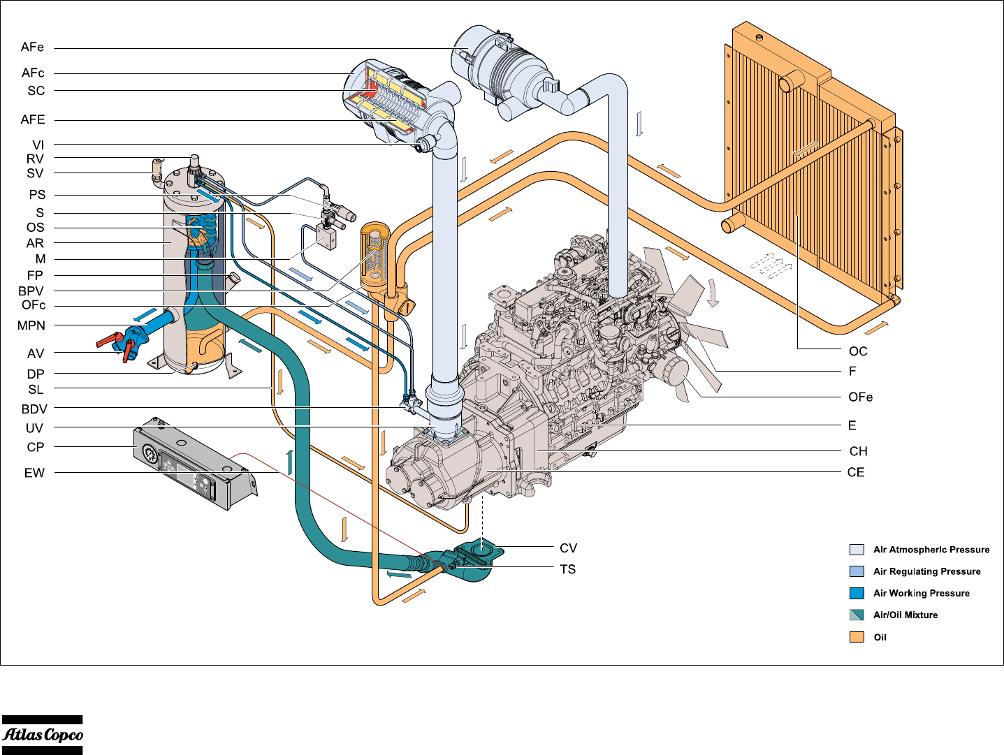
Reference Name
AFc Air Filter Compressor
AFe Air Filter Engine
AFE Air Filter Element
AR Air Receiver
AV Air Outlet Valve
BDV Blow Down valve
BPV By-Pass Valve Oil Filter
CE Compressor Element
CH Coupling Housing
CP Control Panel
CV Check Valve
DP Drain Plug
E Engine
EW Electrical Wiring
F Cooling Fan
FP Compressor Oil Filling Plug
Reference Name
M Manifold
MPN Minimum Pressure Nozzle
OC Oil Cooler
OFc Oil Filter (Compressor)
OFe Oil Filter (Engine)
OS Oil Separator
PS Pressure Sender
RV Regulating Valve
S Solenoid
SC Safety Cartridge
SL Scavenge Line
SV Safety Valve
TS Temperature Switch
UV Unloader Valve
Vi Vacuum Indicator

- 18 -
Air flow
The system comprises:
Air drawn through the airfilter (AF) into the compressor
element (CE) is compressed. At the element outlet,
compressed air and oil pass into the air receiver/oil
separator (AR/OS).
In the air receiver/oil separator (AR/OS), most of the oil is
removed from the air/oil mixture: the remaining oil is
removed by the separator element.The oil collects in the
receiver and on the bottom of the separator element.
The oil collects in the receiver and on the bottom of the
separator element.
The air leaves the receiver via the minimum pressure
nozzle (MPN) which prevents the receiver pressure from
dropping below the minimum working pressure, even
when the air outlet valves are open. This ensures adequate
oil injection and prevents oil consumption.
A temperature switch (TS) and a working pressure gauge
(PG) are comprised in the system.
A blow-down valve (BDV) is fitted in the unloader
assembly to automatically depressurize the air receiver
(AR) when the compressor is stopped.
Oil system
The system comprises:
The lower part of the air receiver (AR) serves as oil tank.
Air pressure forces the oil from the air receiver/oil
separator (AR/OS) through the oil cooler (OC) and oil
filter (OF) to the compressor element (CE).
The compressor element has an oil gallery in the bottom of
its casing. The oil for rotor lubrication, cooling and sealing
is injected through holes in the gallery.
Lubrication of the bearings is ensured by oil injected into
the bearing housings.
The injected oil, mixed with the compressed air, leaves the
compressor element and re-enters the air receiver, where it
is separated from the air as described in section 2.4. The
oil that collects in the bottom of the oil separator element
is returned to the system through scavenging line (SL),
which is provided with a flow restrictor (FR).
The oil filter by-pass valve opens when the pressure drop
over the filter is above normal because of a clogged filter.
The oil then by-passes the filter without being filtered. For
this reason, the oil filter must be replaced at regular
intervals.
Continuous regulating system
The system comprises:
The compressor is provided with a continuous regulating
system. This system is provided with a blow-down valve
(BDV) which is integrated in the unloader assembly (UA).
The valve is closed during operation by outlet pressure of
the compressor element and opens by air receiver pressure
when the compressor is stopped.
When the air consumption increases, the air receiver
pressure will decrease and vice versa. This receiver
pressure variation is sensed by the regulating valve which,
by means of control air to the unloader, matches the air
output to the air consumption. The air receiver pressure is
maintained between the pre-selected working pressure and
the corresponding unloading pressure. When starting the
compressor, the unloader valve (UV) is kept open by
spring force, the engine runs at maximum speed. The
compressor element (CE) takes in air and pressure builds
up in the receiver. The unloader valve is closed.
The air output is controlled from maximum output (100%)
to no output (0%) by:
1. Speed control of the engine between maximum load
speed and unloading speed (the output of a screw
compressor is proportional to the rotating speed).
2. Air inlet throttling.
3. Blow off valve (BOV).
If the air consumption is equal to or exceeds the maximum
air output, the engine speed is held at maximum load speed
and the unloading valve is fully open.
If the air consumption is less than the maximum air output,
the regulating valve supplies control air to unloader valve
(UV) to reduce the air output and holds air receiver
pressure between the normal working pressure and the
AF Air filter
AR/OS Air receiver/oil separator
CE Compressor element
UA/UV Unloader assembly with unloader valve
BDV Blow-down valve
MPV Minimum pressure valve
LV Loading Valve
AR/OS Air receiver/oil separator
RV/UA Regulation Valve/Unloader Valve
OC Oil cooler
OF Oil filter
RV Regulating valve
UA Unloader Valve
SR Speed regulator

- 19 -
corresponding unloading pressure of approx. 21.75 psi
(1.5 bar) above the normal working pressure.
When the air consumption is resumed, the unloader valve
gradually opens the air intake and the speed regulator
increases the engine speed.
The construction of the regulating valve is such that any
increase (decrease) of the air receiver pressure above the
pre-set valve opening pressure results in a proportional
increase (decrease) of the control pressure to the
unloading valve.
Part of the control air is vented to atmosphere, and any
condensate discharged, through the vent holes (VH).

- 20 -
Electric system
CIRCUIT DIAGRAM - 1310 3200 51

- 21 -

- 22 -
Operating instructions
Parking, towing and lifting instructions
Safety precautions
Attention
DRAWBAR PREPARATIONS FOR TOWING
Atlas Copco XAS 185 KD7 compressors may be supplied
to a customer with a folded drawbar. The drawbar is
positioned in it’s upright position for shipping purposes
only. When the compressor is received by the end
customer, the drawbar will need to be put into it’s
operating position. To do this:
1. With the weight of the compressor still on the drawbar,
pull the pin on the jacking device (prop or nose wheel)
and move it into the down position. Be sure to re-
insert the pin to keep the jack locked in place.
2. Use the jack to support the compressor in a level
position by turning the handle at the top of the jack.
3. Using the appropriate tools, remove the shipping
bracket and fold the drawbar into it’s down position.
Disgard locknut.
Note: take the necessary precautions as to not pinch
the wire harness that runs through the drawbar during
the unfolding process. Pull the excess harness out
through the front of the drawbar.
4. Reuse the shipping bracket bolt to secure the drawbar
by reinserting the bolt through both drawbar halves
(item 2, 3). Secure and tighten with the locknut sup-
plied in the shipping bag. Torque the nut and bolt to
130 ft-lbs.
5. Using a jack stand or by blocking, support the end of
the drawbar. With the compressor properly supported
remove the prop or nose wheel and tighten the pivot
nut/bolt. Torque the nut and bolt to 130 ft-lbs.
6. Re-attach the prop to the drawbar in the down posi-
tion and install keeper pin. Jack the unit up with the
prop to remove the blocking.
7. Using bolt, washers, and locknut (items 4,5,6) from
shipping bag, insert bolt through hole on top of draw-
bar using washers and secure with locknut. Torque
nut and bolt to 130 ft-lbs.
8. Discard any remaining hardware and the shipping
bracket.
9. Retorque the all drawbar attachment bolts to their
specified value after 5-10 hours of use.
Note: the pivoting feature of the drawbar is for
shipping purposes only. The drawbar is to remain in
the down position after it’s initial setup. REUSE OF
LOCKNUTS IS STRICTLY PROHIBITTED BY
ATLAS COPCO
The operator is expected to apply all
relevant Safety precautions for portable
compressor.
Check and retighten the wheel nuts and
drawbar bolts to the specified torque. See
section Technical Specifications.
1
3
2
4
5
5
6

- 23 -
Starting / Stopping
Safety precautions
Battery switch
If the compressor is equipped with a battery switch:
When the compressor is not in use this switch must always
be in the “OFF” position.
It is not allowed to use this switch as an emergency switch
or for stopping the compressor. It will cause damage in the
control unit when using this switch for stopping.
Always first shut off the control unit and wait until the
display is dark before switching the battery switch to
position “OFF”.
Control panel
Do not disconnect power supply to control
box in any way when the control box is
switched on. This will cause memory loss.
Do not switch off the circuit breaker when
the control box is switched on. This will
cause memory loss.
Please be aware that the (optional)
preheater unit is still “live” with the battery
switch in “OFF” position.
Reference Name
START BUTTON: This button will initiate
the starting sequences if the controller is in
Ready To Start Sequence, or will re-enter the
normal running sequence when in Cooldown
Sequence.
STOP BUTTON: This button will initiate the
cooldown/stopping sequences if the controller
is in normal running sequence.
LOAD BUTTON: This button will:- initiate
the Auto Load function when the controller is
in normal running sequence, but not ready to
be loaded.
- initiate the loading sequences when the
controller is ready to be loaded.
- initiate the not loaded sequence when the
controller is running in Loaded Sequence
MEASUREMENTS VIEW BUTTON: This
button will enter the Measurements View when
not already in the Measurements View, or
when already in the Measurements View it will
enter the Main View.
SETTINGS VIEW BUTTON: This button
will enter the Settings View when not already
in the Settings View, or when already in the
Settings View it will enter the Main View.
ALARMS VIEW BUTTON: This button will
enter the Alarms View when not already in the
Alarms View, or when already in the Alarms
View it will enter the Main View.
NAVIGATION BUTTONS: These buttons
are used to navigate through the display
menu’s.
ENTER BUTTON: Confirms/stores the
selection/change.
BACK BUTTON: Moves back one level or
ignores the change.

- 24 -
OVERVIEW ICONS
Reference Name
1 Compressor status
2 Vessel pressure indication or info text
3 Compressor info
Main View Indication
Measuring View Indication
Settings View Indication
Alarm View Indication
DPF REGENERATION
High Exhaust System Temperature.
Means that the Diesel Particle Filter
is being regenerated.
DPF REGENERATION NEEDED
Means that the Diesel Particle Filter
needs to be regenerated.
Please force DPF Regeneration.

- 25 -
Reference Name
DPF REGENERATION INHIBITED
Diesel Particle Filter Regeneration
Inhibited.
Means that the DPF regeneration is
inhibited, even if all criteria to
activate a regeneration are met.
OVERHAUL
Initial Overhaul required.
OVERHAUL
Minor Overhaul required.
OVERHAUL
Major Overhaul required.
AUTO LOAD
This icon will be shown if the Auto Load
functionality is enabled, or by means of a
parameter setting, or by means of pressing the
load button before the machine is ready to be
loaded.
Reference Name
OPERATION MODE
Local
OPERATION MODE
Remote
ALARM
Active & not-acknowledged Shutdown Alarm.
ALARM
Active & not-acknowledged Non-Shutdown
Alarm.
ALARM
Active & acknowledged Alarm.
FUELTANK
Running at internal fueltank.

- 26 -
Possible views
Main View
Measuring View
Use the Up and Down navigation buttons to scroll through
the full list of measurements.
Setup View
Use the Up and Down navigation buttons to scroll through
the full list of settings.
Use the Enter button to enter the selected submenu.
Use the Back button to leave the entered (sub)menu.
Alarm View
Use the Up and Down navigation buttons to scroll through
the full list of alarms.
The DM Lists and the Log Lists can be selected and
entered to access the sublist.

- 27 -
STARTING
Switch on the battery switch if so equipped.
Switch the controller on by pressing the power button.
The instrument panel will now perform a selftest; the
following display will be shown and the controller is
initialized:
During initializing all buttons/inputs/outputs/alarms are
inactive.
This view will be shown for about 2 seconds, after which
the display will show the Main View.
The actual vessel pressure is shown. If the measured
vessel pressure is higher than 1.5 bar, the unit will not
start. The vessel pressure has to be lowered by opening the
blow down valve. After power up, the vessel pressure
normally is low enough to proceed with the starting
procedure.
The display now shows
The machine is now ready to be started and is waiting for
a start command.
The display now shows
After pressing the START button, the engine electronics
(ECU) will be powered up.
As soon as communication between compressor controller
and engine controller is established, the machine will
preheat according to the parameters of the engine
controller.
Xc2003
v1.00.0 (r7307)
Active Buttons
Measurement View Button
Settings View Button
Alarms View Button
Active Buttons
Start Button
(to initiate Start command)
Measurement View Button
Settings View Button
Alarms View Button

- 28 -
The display now shows
The engine starts cranking, the display shows
The engine cranks until 800 rpm is reached.
If 800 rpm is not reached within 30 seconds, the starting
procedure is cancelled and the engine will rest for some
time. (Resting time depends on cranking time).
The display now shows
Active Buttons
Stop Button
(to cancel Start command)
Measurement View Button
Settings View Button
Alarms View Button
Active Buttons
Stop Button
(to cancel Start command)
Measurement View Button
Settings View Button
Alarms View Button

- 29 -
The engine starts running at idle speed. The display shows
The engine will run at minimum rpm, until the engine’s
coolant temperature reaches 40 deg C (104 deg F), with a
minimum time of 15 seconds and a maximum time of 300
seconds.
The display now shows After warming up the machine is ready to be loaded and is
waiting for a load command; the display shows
Active Buttons
Stop Button
(to cancel Start command)
Measurement View Button
Settings View Button
Alarms View Button
Active Buttons
Stop Button
(to cancel Start command)
Load Button
(to initiate Automatic Load)
Measurement View Button
Settings View Button
Alarms View Button

- 30 -
The engine will now run at maximum rpm, the display will
show
The loading valve will be energized and pressure starts
building up.
During loading the following display is shown (default
display)
The controller controls the speed of the engine in order to
meet the requested working pressure, at the most
economical fuel usage.
During operation
Regularly carry out following checks:
1. Ensure that the regulating valve (RV) is correctly
adjusted, i.e. starts decreasing the engine speed when
reaching the preset working pressure in the receiver.
2. Check the air outlet temperature of the compressor
element.
3. Check the engine oil pressure, the coolant tempera-
ture and display of control box.
4. Avoid the engine running out of fuel. Nevertheless, if
this happens, fill the fuel tank and prime the fuel sys-
tem to speed up starting.
Active Buttons
Stop Button
(to cancel Start command)
Load Button
(to cancel Load command)
Measurement View Button
Settings View Button
Alarms View Button
Active Buttons
Stop Button
(to cancel Start command)
Load Button
(to cancel Load command)
Measurement View Button
Settings View Button
Alarms View Button
The doors must be closed during operation
and may be opened for short periods for
inspection and adjustments only.
Be aware not to touch hot or moving parts
when the door is open.
When the engine is running, the air outlet
valves (ball valves) must always be put in a
fully opened or fully closed position.

- 31 -
STOPPING
After pressing the STOP button the display will show:
After a Stop command, or in case of a controlled stop
alarm, the machine will cool down and run at minimum
rpm for 1 minute before it will stop.
After cooling down the engine will stop and the display
will show
The engine is stopped, and the controller will do a double
check to see if the engine is really stopped.
Active Buttons
Start Button
(to initiate Start command)
Measurement View Button
Settings View Button
Alarms View Button
Active Buttons
Start Button
(to initiate Start command)
Measurement View Button
Settings View Button
Alarms View Button

- 32 -
SHUTDOWN
When the machine is shutdown due to a critical alarm or
an emergency stop the display will show
POWER OFF
Switch the controller off by pressing the Power button.
If the compressor is equipped with a battery switch:
When the compressor is not in use, this switch must
always be in the “OFF” position.
It is not allowed to use this switch as an emergency switch
or for stopping the compressor.
It can damage the controller or the engine’s Electronic
Control Unit when using the battery switch for stopping.
Always first shut off the controller and wait until the
display is dark before switching the battery switch to
position “OFF”.
DIESEL PARTICULATE FILTER
REGENERATION
When the Diesel Particle Filter regeneration process is
kept at its default ‘AUTOMATIC’ setting, then the DPF
regeneration will be performed automatically when the
Soot Load exceeds 60%.
The controller display will indicate an ongoing DPF
Regeneration by showing the HEST icon (High Exhaust
System Temperature):
The DPF regeneration process will continue, until the Soot
Load has become as low as possible, or until the engine is
stopped.
When the DPF regeneration process is stopped, the HEST
icon will disappear from the display.
Active Buttons
Measurement View Button
Settings View Button
Alarms View Button
Enter Button
(to acknowledge the shown alarm)
HEST Icon

- 33 -
AUTOMATIC DPF REGENERATION
(DEFAULT)
In specific cases, when the engine speed is constant at
Minimum RPM, it can happen that the DPF regeneration
already starts from 30% Soot Load (LSR - Low Speed
Regeneration).
This can happen in following situations:
• Warming Up
• Not Loaded
• Loaded (when running in Unload condition - mini-
mum RPM)
• Cooldown
When an LSR is ongoing while the soot load is less than
60%, and the engine speed changes (engine is stopped,
machine gets loaded, …), then the DPF Regeneration
process will be stopped.
If the Soot Load is higher than 30% when cooling down
should start (then an LSR is expected to be started) the
controller will ask:
If Enter is pressed within 10 seconds then the controller
will allow the DPF regeneration to be completed before
the engine is stopped.
If Enter is not pressed (within 10 seconds), then the engine
will be stopped after cooling down.
INHIBIT DPF REGENERATION
When running in an environment where an elevated
exhaust temperature is not allowed, it might be necessary
to inhibit DPF regeneration. This has to be done at
Customer Service Level. Go to General settings 1000.
Parameter 1142 ECU DPF Regeneration Enable - Set to
"OFF". The controller has now put the DPF Regeneration
in a FORCED OFF mode, which is Inhibit DPF
Regeneration.
The compressor controller will communicate with the
engine controller and the (RED) Inhibit DPF regeneration
icon will appear:
When the controller gets powered down, it will (at next
power up) fall back to its default settings, meaning
AUTOMATIC DPF regeneration.
INCREASING SOOT LOAD
When the DPF Regeneration is Inhibited, or when the
engine does not get sufficient possibility to automatically
perform a full DPF Regeneration, the Soot Load will
exceed the normal levels.
The controller will show the DPF Regeneration Needed
Icon. In case of Inhibited DPF Regeneration, the DPF
Regeneration Needed Icon will overwrite the DPF
Inhibited Icon.
Required Action:
• Force DPF Regeneration, see paragraph FORCE
DPF REGENERATION
When DPF Regeneration is started, the DPF Regeneration
Needed icon will disappear and the HEST icon will pop-
up.
A full DPF Regeneration can take up to an
hour.
DPF Regeneration Inhibited.
DPF Regeneration needed

- 34 -
TURNING REGENERATION BACK TO AUTO
Machine is not running:
Power the controller down. At next power up, the DPF
Regeneration settings will be back to default, and an
Automatic DPF Regeneration will take place at the
soonest appropriate moment.
Machine is running:
• Press the Settings View Button
• Enter the '1000 GENERAL SETTINGS' menu
• Scroll one line down and Enter the ‘1140 ECU DPF
REGENERATION’ menu
• Scroll down and Enter the 'MODE' parameter
• Scroll down and Enter the 'AUTOMATIC' setting
• Press the Back button 3 times to get back to the Main
view
• Also make sure parameter '1142 ECU DPF REGEN-
ERATION ENABLE' is set to "ON"
DPF Regeneration setting will now be AUTOMATIC
DPF REGENERATION.
Customer Level can now select between AUTO
Regeneration & INHIBIT Regeneration, as long as the
controller is not powered down (after power down, it will
fall back to its default DPF Regeneration settings, and a
Service Level is needed to go back to Inhibit DPF
Regeneration).
FORCE DPF REGENERATION
Machine is running:
• Press the Settings View Button
• Enter the '1000 GENERAL SETTINGS' menu
• Go to parameter '1130 STATIONARY REGENERA-
TION'
• Scroll to Enable and change to "ON"
SERVICE REGENERATION
Machine is running:
• Press the Settings Menu
• Enter the '7000 ENGINE' menu
• Go to parameter '7140 SERVICE REGENERA-
TION'
• Scroll to Enable and change to "ON"
SETTINGS
For buttons to be used see “Control Panel”
Acknowledge an Alarm
If an alarm becomes active, for example a Low Fuel Level
Warning:
then this alarm can be acknowledged by pressing the
ENTER button. If the fuel level is still low, the view
will change to:
As soon as the fuel level is higher than the warning level,
the alarm icon will automatically disappear.
As long as there is an alarm icon in the middle of the
bottom part of the view, all active acknowledged /
Unit will not regenerate if soot level is not
high enough.
Unit will not regenerate if soot level is not
high enough.

- 35 -
unacknowledged alarms can be seen by pressing the
ALARM VIEW button
Pressing the ALARM VIEW button again, will bring you
back to the Main View.
Set Clock
Press the SETTINGS VIEW button
• scroll to ‘1000 GENERAL SETTINGS’
• press ENTER
• scroll to ‘1290 DATE/TIME’
• ENTER the Date/Time menu
• scroll to the parameter you want to change
• ENTER this parameter.
To change the ‘Month’, scroll to the preferred month and
press ENTER.
To change any other setting, the highlighted figure is
editable.
Scroll up/down and press ENTER to change. Use left/
right to shift between editable figures.
Now press BACK until you’re back in the Main View (or
in the menu you require).
Set Language
Press the SETTINGS VIEW button.
• scroll to ‘1000 GENERAL SETTINGS’
• press ENTER
• scroll to ‘1300 LANGUAGES’
• ENTER the LANGUAGES menu,
• ENTER the ‘SETTINGS’ parameter
• scroll to the preferred language
• press ENTER.
Now press BACK until you’re back in the Main View (or
in the menu you require).
Set Units
Press the SETTINGS VIEW button,
• scroll to ‘1000 GENERAL SETTINGS’
• press ENTER
• scroll to the unit you would like to change:
‘1340 TEMPERATURE UNITS’
‘1350 PRESSURE UNITS’
‘1360 FUEL FLOW UNITS’
• ENTER the preferred menu
• ENTER the ‘SETTINGS’ parameter
• scroll to the preferred setting
• press ENTER.
Now press BACK until you’re back in the Main View (or
in the menu you require).
Change Display Settings
Press the SETTINGS VIEW button
• scroll to ‘1000 GENERAL SETTINGS’
• press ENTER
• scroll to ‘1310 DISPLAY BACKLIGHT’
• ENTER the DISPLAY BACKLIGHT menu
• scroll to the setting you would like to change
• press ENTER.
To change a setting, the highlighted figure is editable.
Scroll up/down and press ENTER to change. Use left/
right to shift between editable figure.
Now press BACK until you’re back in the Main View (or
in the menu you require).
Go To Diagnostics
Press the SETTINGS VIEW button
• scroll to ‘1000 GENERAL SETTINGS’
• press ENTER
• scroll to ‘1150 DIAGNOSTICS’
• ENTER the Diagnostics menu,
• ENTER the ‘ENABLE’ parameter
• scroll to ‘ON’ and press ENTER.
Now the ECU will get power and one can perform ECU
diagnostics (read DM1 List, DM2 List, ECU values,
perform engine diagnostics, …).
Now press BACK until you’re back in the Main View (or
in the menu you require).
To leave Diagnostics, press the STOP button.
• ECU warning 7009 will be active while in diagnos-
tics.

- 36 -
FAULT CODES
There are several parameters that are continuously
watched.
When one of these parameters exceeds its specified limit
the compressor will react depending the present status of
the control box.
Alarmcode Alarmtext Failclass Trigger
1231 FUEL FILL CHECK Warning Xc
1503 INITIAL OVERHAUL REQUIRED Warning Xc
1522 MINOR OVERHAUL WITHIN ** H Warning Xc
1523 MINOR OVERHAUL WITHIN ** D Warning Xc
1524 MINOR OVERHAUL REQUIRED Warning Xc
1552 MAJOR OVERHAUL WITHIN ** H Warning Xc
1553 MAJOR OVERHAUL WITHIN ** D Warning Xc
1554 LOAD PREVENTION - FIRE RISK Inhibit Load Xc
1558 COMP. OIL CHANGE WITHIN ** H Warning Xc
1559 COMP. OIL CHANGE WITHIN ** D Warning Xc
2000 EMERGENCY STOP INPUT Shutdown Xc
2040 REMOTE EMERGENCY STOP Shutdown Xc
2070 COOLANT LEVEL LOW WARNING Warning Xc
2080 COOLANT LEVEL LOW SHUTDOWN Shutdown Xc
2090 ΔP AIRFILTERS HIGH Warning Xc
2100 NO PROJECTFILE DOWNLOADED Warning Xc
2752 NAM OILTRONIX BYPASS CIRCUIT Shutdown After Stop Xc
2762 NAM OILTRONIX CLOSED CIRCUIT Shutdown After Stop Xc
2772 NAM AIRXPERT OPENED CIRCUIT Shutdown Xc
2782 NAM AIRXPERT CLOSED CIRCUIT Shutdown Xc
3000 FUEL LEVEL LOW WARNING Warning Xc
3010 FUEL LEVEL LOW SHUTDOWN Controlled Stop Xc
3020 FUEL LEVEL SENSOR CIRCUIT Warning Xc
3050 VESSEL PRESSURE HIGH WARNING Controlled Stop Xc
3060 VESSEL PRESSURE HIGH SHUTDOWN Shutdown Xc
3070 VESSEL PRESSURE SENSOR CIRCUIT Shutdown Xc
3120 REGULATING PRESSURE SENSOR CIRCUIT Shutdown Xc
3170 AIR DISCHARGE PRESSURE SENSOR CIRCUIT Warning Xc
3320 INLET PRESSURE SENSOR CIRCUIT Shutdown Xc
3450 BATTERY LOW ALARM Indication Xc
3460 BATTERY HIGH ALARM Warning Xc
3660 FIRE RISK - CHECK OILSTOPVALVE Shutdown Xc
3680 OSV PRESSURE SENSOR CIRCUIT Controlled Stop Xc
3720 INTERSTAGE PRESSURE SENSOR CIRCUIT Warning Xc
4000 L.P. ELEMENT TEMPERATURE HIGH Warning Xc
4010 L.P. ELEMENT TEMP. ALARM 2 Controlled Stop Xc
4020 L.P. ELEMENT TEMP. ALARM 3 Shutdown Xc

- 37 -
4040 L.P. ELEMENT TEMP. SENSOR CIRCUIT Shutdown Xc
4070 AMBIENT TEMPERATURE SENSOR CIRCUIT Warning Xc
4100 AIR DISCHARGE TEMPERATURE ALARM 1 Warning Xc
4110 AIR DISCHARGE TEMPERATURE ALARM 2 Controlled Stop Xc
4120 A.D. TEMPERATURE SENSOR CIRCUIT Warning Xc
4150 H.P. ELEMENT TEMPERATURE ALARM 1 Warning Xc
4160 H.P. ELEMENT TEMPERATURE ALARM 2 Controlled Stop Xc
4170 H.P. ELEMENT TEMPERATURE ALARM 3 Shutdown Xc
4190 H.P. ELEMENT TEMP. SENSOR CIRCUIT Shutdown Xc
4220 AFTERCOOLER AIR TEMP SENSOR CIRCUIT Warning Xc
4230 AFTERCOOLER FREEZING DANGER Indication Xc
5200 AIR SHUT OFF Shutdown Xc
6190 CHARGE MONITORING FAIL Indication Xc
6327 START FAILURE Shutdown Xc
6329 STARTER SPEED TOO LOW Shutdown Xc
6388 VESSEL PRESSURE TOO LOW TO LOAD Indication Xc
6426 UNINTENTIONAL RUN Shutdown Xc
6427 RUN FAILURE Shutdown Xc
6428 STOP FAILURE Shutdown Xc
6708 DRAINING 1 Warning Xc
6709 DRAINING 2 Warning Xc
6749 OILTRONIX FUNCTIONALITY DISABLED Warning Xc
6760 OILTRONIX COUPLING FAILURE Shutdown After Stop Xc
6769 OILTRONIX COMPONENT FAILURE Shutdown Xc
6981 INLET VALVE POS. FAILURE Shutdown Xc
7002 ECU COMMUNICATION Shutdown Xc
7007 ECU RED LAMP Shutdown ECU
7008 ECU AMBER LAMP Warning ECU
7009 ECU PROTECT LAMP Warning ECU
7010 ECU ENGINE SPEED TOO LOW Shutdown Xc
7020 ECU ENGINE SPEED ALARM 2 Shutdown Xc
7030 ECU ENGINE COOLANT TEMP. ALARM Controlled Stop Xc
7050 ECU ENGINE AIR INLET TEMP. ALARM 1 Controlled Stop Xc
7100 ECU DPF SOOT LOAD HIGH Warning Xc
7110 PLEASE FORCE DPF REGENERATION ! Inhibit Load Xc
7120 LOAD PREVENTION - HIGH DPF SOOT LOAD Controlled Stop Xc
7130 SOOT LOAD TOO HIGH - CALL ATLAS COPCO Warning Xc
7222 COMBO COMMUNICATION FAILURE Warning Xc
7223 COMBO PA SENSOR WARNING Warning Xc
7224 COMBO RHA SENSOR WARNING Warning Xc
7225 COMBO TA SENSOR WARNING Warning Xc
Alarmcode Alarmtext Failclass Trigger

- 38 -
Details of ECU triggered alarms can be monitored via the ECU DM1 LIST menu
In case of ECU AMBER LAMP or ECU PROTECT LAMP:
Only possible when engine is running or if Diagnostics
Mode is active.
Access the ECU DM1 LIST menu via Alarm View.
In case of ECU RED LAMP:
Do NOT acknowledge the ECU RED LAMP alarm.
DM1 alarms are automatically copied into the Alarm
View, and can be read there.
For all ECU triggered alarms, the respective SPN code is
shown in the ECU DM1 LIST
A full list of supported SPN codes is provided by the engine
manufacturer.
For following alarms, the Xc controller also shows full text
next to the SPN code:
ECU - FUEL FILTER PRESSURE
ECU - INTERCOOLER TEMPERATURE
ECU - FUEL PRESSURE
ECU - FUEL FILTER PRESSURE
ECU - WATER IN FUEL
ECU - OIL LEVEL
ECU - OIL FILTER PRESSURE
ECU - OIL PRESSURE
ECU - TURBO BOOST PRESSURE
ECU - TURBO OIL PRESSURE
ECU - INTAKE MANIFOLD TEMPERATURE
ECU - AIR INLET PRESSURE
ECU - COOLANT TEMPERATURE
ECU - COOLANT LEVEL
ECU - SUPPLY VOLTAGE
ECU - AMBIENT AIR TEMPERATURE
ECU - AIR INLET TEMPERATURE
ECU - FUEL TEMPERATURE
ECU - OIL TEMPERATURE
ECU - ENGINE SPEED
ECU - INJECTOR 1
ECU - INJECTOR 2
ECU - INJECTOR 3
ECU - INJECTOR 4
ECU - INJECTOR 5
ECU - INJECTOR 6
ECU - INJECTOR 7
ECU - INJECTOR 8
ECU - SOOT LOAD

- 39 -
EMERGENCY STOP
When an emergency stop button (1) is pressed, power to
all outputs is terminated, by the emergency stop itself
(hardware) as well as by the software.
When the emergency stop button (1) is pressed the
operator can unlock the emergency stop by turning it
counterclockwise.
The emergency stop button is only to be
used in emergency situations; not for
stopping procedures.
(1)

- 40 -
PARKING INSTRUCTIONS
When parking a compressor, secure prop (1) or nose wheel
to support the compressor in a level position. Place the
compressor as level as possible; however, it can be
operated temporarily in an out-of-level position not
exceeding 15°. If the compressor is parked on sloping
ground, immobilize the compressor by placing wheel
chocks in front of or behind the wheels. Locate the
compressor upwind, away from contaminated wind-
streams and walls. Avoid recirculation of exhaust air from
the engine. This causes overheating and engine power
decrease.
TOWING INSTRUCTIONS
Before towing the compressor, make sure that the towing
equipment of the vehicle matches the towing eye or ball
connector
The drawbar should be as level as possible and the
compressor and towing eye end in a level position. Secure
nose prop (1) in the highest position. Attach safety chains/
cables in a crisscross manner to the tow vehical. This will
help prevent the towbar from contacting ground in event
of a breakaway. Connect road lights when applicable.
LIFTING INSTRUCTIONS
When lifting the compressor, the hoist has to be placed in
such a way that the compressor, which must be placed
level, will be lifted vertically. Use the lifting bale provided
to lift the unit
Before Starting
1. Before initial start-up, prepare battery for operation if
not already done.
2. With the compressor standing level, check the level of
the engine oil. Add oil, if necessary, to the upper mark
on dipstick. Consult the Engine Operation Manual for
the type and viscosity grade of the engine oil.
3. Check the level of the compressor oil. The pointer of oil
level gauge (OLG) should register in the green range.
Add oil if necessary.
4. Check that the fuel tank contains sufficient fuel. Top
up, if necessary. Consult the Engine Operation Man-
ual for the type of fuel.
5. Check coolant level in overflow bottle. Top off coolant
if necessary. Consult engine’s operation manual for
water/coolant specifications.
6. Drain any water and sediment from the fuel filter until
clean fuel flows from the drain cock.
7. Press vacuator valve (VV) of the air filter to remove
dust.
8. Check the air filter service indicator (VI). If the red part
shows completely, service or replace the filter element.
Reset the indicator.
9. Open an air outlet valve (AV) to allow air flow to the
atmosphere.
Lifting acceleration and retardation must
be kept within safe limits (max. 2g).
Helicopter lifting is not allowed.
If the compressor is to be connected to a
common compressed air system, fit an
appropriate check valve between
compressor outlet and air system. Observe
the right mounting position/direction!

- 41 -
Maintenance
Use of Service Paks
Service Paks include all genuine parts needed for normal maintenance of both compressor
and engine. Service Paks minimize downtime and keep your maintenance budget low.
You may order Service Paks from your local Atlas Copco dealer.
Preventive Maintenance Schedule For The Compressor
The schedule contains a summary of the maintenance instructions.
Read the respective section before taking maintenance measures.
When servicing, replace all disengaged packings, e.g. gaskets, 0-rings, washers.
For engine maintenance refer to Engine Operation Manual.
The maintenance schedule has to be seen as a guideline for units operating in a duty
environment typical to compressor applications. Maintenance schedule can be adapted
depending on application environment and quality of maintenance
• When the battery is used for less than 100 hours in a year, check its electrolyte
yearly. (for refillable battery's only)
• *1: When biodiesel fuel is used, change the fuel filter cartridge, fuel hose and clamp
bands with new ones at intervals half of the usual ones.
• *2: Consult your local KUBOTA dealer for this service.
• The items in the engine manual marked *3 are registered as emission related critical
parts by KUBOTA in the U.S. EPA nonroad emission regulation. As the engine
owner, you are responsible for the performance of the required maintenance on the
engine according to the above instruction. Please see the warranty statement in
detail.
• The items listed above are not necessary to keep the emission-related warranty
valid.
• Failure to perform the maintenance will cause problems that will significantly
degrade the engine performance.
API service classification: above CJ-4 grade
Ambient temperature: below 35 °C (95 °F)
MAINTENANCE SCHEDULE Daily Initial 50hours + Every
250/750 hours
1310 9230 03
Every 500 hours
1310 9230 04
Every 1000 hours
1310 9230 05
Note
Check engine oil level Check
Check of fuel level Check
Check of coolant level Check
Check of fan belt Check Change Change
Change of engine oil Change Change Change See change interval
Replacement of oil filter cartridge Replace Replace w/ oil change Replace w/ oil change
*1- Replacement of fuel filter cartridge Replace Replace
Cleaning of water separator Check
*2- Cleaning of fuel tank interior Check
*2- Cleaning of water jacket and radiator interior Check
*2- Replacement of fan belt Check
*2- Check of valve clearance Check
When changing or inspecting, be sure to
level and stop the engine.
Changing interval of engine oil:
Models Interval
V2403 Every 400 hours

- 42 -
Technical Specifications
Reference conditions
The inlet conditions are specified at the air inlet grating outside the canopy.
Limitations
Designation XAS 185 KD7
Absolute inlet pressure bar(e) 1
psi 14.7
Relative air humidity % 0
Air inlet temperature °C 20
°F 68
Normal effective working pressure bar(e) 7
psi 100
Designation XAS 185 KD7
Minimum effective receiver pressure bar(e) 4
psi 58
Maximum effective receiver pressure,
compressor unloaded
bar(e) 8.4-8.7
psi 120-125
Maximum ambient temperature at sea level °C 52
°F 125
Minimum starting temperature °C -10°C tested @ 12°C
°F +14°F
Minimum starting temperature,
with coldstart equipment
°C NA
°F NA
Altitude capability see curves

- 43 -
ALTITUDE UNIT PERFORMANCE CURVE

- 44 -
Performance data
1)
Design Data
COMPRESSOR
ENGINE
UNIT
Designation XAS 185 KD7
Engine shaft speed, normal and maximum rpm 2700
Engine shaft speed, compressor unloaded rpm 1600
Free air delivery
2)
l/s 83.53
cfm 177
Fuel consumption -at full load gal/hr 2.33
-at unload gal/hr 0.94
Specific fuel consumption gal/ft
3
0.00022
Typical oil content of compressed air mg/m
3
<5
oz/1000 cu.ft < 0.005
Engine oil consumption (maximum) g/hr NA
oz/h NA
Compressed air temperature at outlet valves °C 93.3
°F 200
Noise level
6)
dB(A) <76
Designation All units
Number of compression stages 1
Designation XAS 185 KD7
Make Kubota
Type V2403
Coolant
Ethylene glycol mix w/SCA
package
Number of cylinders 4
Bore
in 3.43
mm 87.12
Stroke
in 4.03
mm 102.36
Swept volume
cu.in 148.53
l2.43
Output at normal shaft speed
5)
hp 49
kW 36.53
- Load factor % 80
Capacity of oil sump
qts 10
gal 2.5
-Refill (max.)
4)
qts 11
gal 2.75
Capacity of cooling system
qts 10
gal 2.5
Designation All units
Capacity of compressor oil system
qts 12.2
gal 3.05
Net capacity of air receiver
US gal 4.5
l 17.03
Capacity of fuel tanks
US gal 20.1
l 76.08
Air volume at inlet grating (approx.)
3)
cfm 6340
m
3
/s 2.99
Designation XAS 185 KD7

- 45 -
1) At reference conditions, if applicable, and at normal shaft speed unless otherwise stated.
2) Free Air Delivery (volume flow rate) is measured according to ISO 1217 ed.3 1996 annex D
Tolerance:
• +/- 5% 25 l/s (53 cfm) < FAD < 250 l/s (530 cfm)
• +/- 4% 250 l/s (530 cfm) < FAD
The international standard ISO 1217 corresponds to following national standards:
• American ANSI PTC9
• British BSI 1571 part 1
• German DIN 1645 Part 1
• Swedish SS-ISO 1217
3) Air required for engine and compressor cooling, combustion and for compression.
4) with filter change
5) Gross power guaranteed within +/- 5% at SAE J1668 and ISO 3046 conditions:
- 77°F air inlet temperature
- 29.31 in. Hg barometer
- 104°F fuel inlet temperature
- 0.853 fuel specific gravity @ 60°F
6) Measured in accordance with ISO 2151 under free field conditions at 7m distance

- 46 -
1. More frequently when operating in a dusty
environment.
2. Replace the element when the pressure drop exceeds
11.5 psi.
3. Refer to the Kubota instruction manual
Lubrication oils
It is strongly recommended to use Atlas Copco branded
lubrication oils for compressor.
Compressor oil
Engine oil
Engine coolant
* Keep the bolts of the housing, the lifting
eye, the towbar and the axle securely
tightened. Refer to Compressor/Engine
Specifications for the torque values.
PAROIL - M
Order number
1 gallon pail: 1615 5947 00
5.2 gallon pail: 1615 5948 00
55 gallon drum: 1615 5949 00
PAROIL - S
Order number
1 gallon pail: 1630 0160 00
5.2 gallon pail: 1630 0161 00
55 gallon drum: 1630 0162 00
264 gallon container: 1630 0163 00
PAROIL - EXTRA 5W40
Order number
1.3 gallon (5 Liter) Container: 1630 0135 01
5.2 gallon (20 Liter) Pail: 1630 0136 01
55 gallon ( 209 Liter) Drum: 1626 0102 00
PAROIL - E MISSION GREEN 15W40
Order number
1.3 gallon (5 Liter) Container: 1630 0471 00
5.2 gallon (20 Liter) Pail: 1630 0472 00
55 gallon ( 209 Liter) Drum: 1630 0473 00
PARCOOL - EG
Order number
1.3 gallon container: 1604 5308 00
5.3 gallon pail: 1604 5307 01
55 gallon drum: 1604 5306 00
1 gallon pail: 1604 8159 00
(1) Additional equipment is needed to run the compressor below 18°F. Please contact Atlas Copco for more
information about Cold Weather Packages
Temperature Range Type of Oil
Compressor Engine
Between -13°F and 122°F
(1)
PAROIL S See Engine Operation Manual
Between 18°F and 104°F
PAROIL M 15W-40
Operation of compressor in ambient temperatures lower than 18°F (-8°C) without the correct
type of oil will void your warranty and may result in element failure and/or fire.

- 47 -
OIL LEVEL CHECK
CHECK ENGINE OIL LEVEL
Consult also the Engine Operation Manual for the oil
specifications, viscosity recommendations and oil change
intervals. See schedule.
Check engine oil level according to the instructions in the
Engine Operation Manual and top up with oil if necessary.
CHECK COMPRESSOR OIL LEVEL
With the unit standing level, engine stopped, check the
level of the compressor oil. The pointer of the oil level
gauge (OLG) must register in the upper extremity of the
green range. Add oil via the oil fill plug (FP) if necessary.
ENGINE OIL AND OIL FILTER CHANGE
Consult also the Engine Operators Manual for oil and oil
filter
(1) change intervals.
(2) oil types.
COMPRESSOR OIL AND OIL FILTER
CHANGE
The quality and the temperature of the oil determine the oil
change interval.
The prescribed interval is based on an oil temperature of
up to 100ºC (212ºF) and normal operating conditions.
When operating in high ambient temperatures, in very
dusty or high humidity conditions, it is recommended to
change the oil more frequently.
1. Run the compressor until warm. Close the outlet
valve(s) and stop the compressor. Wait until the
pressure is released through the automatic blow-
down valve. Unscrew the oil filler plug (FP) one turn.
This uncovers a vent hole, which permits any
pressure in the system to escape.
2. Drain the oil by removing all drain plugs. Drain
plugs are located at the oil tank, discharge manifold,
and oil injection manifold vessel. Catch the oil in a
drain pan. Screw out the filler plug to speed up drain-
ing. Tighten the plugs after draining.
3. Remove the oil filter (OFc), e.g. by means of a spe-
cial tool. Catch the oil in a drain pan.
4. Clean the filter seat on the manifold, taking care that
no dirt drops into the system. Oil the gasket of the
new filter element. Screw it into place until the gas-
ket contacts its seat, then tighten one half turn only.
5. Fill the air receiver until the pointer of the oil level
gauge (OLG) registers in the upper extremity of the
green range. Take care that no dirt drops into the sys-
tem. Reinstall and tighten the filler plug.
6. Run the unit at no load for a few minutes to circulate
the oil and to evacuate the air trapped in the oil sys-
tem.
7. Stop the compressor. Let the oil settle for a few min-
utes. Check that the pressure is released by opening
an air outlet valve (AV). Screw out filler plug (FP)
and add oil until the pointer of the oil level gauge
(OLG) again registers in the upper extremity of the
green range. Reinstall and tighten the filler plug.
Never mix oils of different brands or types
Before removing oil filler plug, ensure that
the pressure is released by opening an air
outlet valve.
In this case, contact Atlas Copco.
Never add more oil. Overfilling results in oil
consumption.

- 48 -
Cleaning Coolers
Keep the coolers clean to maintain the cooling efficiency.
Front cooler baffle is removable for access by unscrewing
4 bolts.
When cleaning by air jet, blow air through the cooler in
reverse direction of normal flow.
If the dirt is oily, wash the coolers with degreaser or a
cleansing agent.
A spray gun should preferably be used to apply the solvent
to the fins. Rinse the blocks by means of a water jet max.
100 psi at 2 inch distance after a soaking-in period. Steam
cleaning may also be applied.
Battery Care
An ASB (Service Bulletin) dealing elaborately with
batteries and due care is available on request.
If the battery is still dry, it must be activated as described
in point 4.7.1.
The battery must be in operation within 2 months from
being activated; if not, it needs to be recharged first.
ELECTROLYTE
Electrolyte in batteries is a sulphuric acid solution in
distilled water.
The solution must be made up before being introduced
into the battery.
RECHARGING A BATTERY
Before and after charging a battery, always check the
electrolyte level in each cell; if required, top up with
distilled water only. When charging batteries, each cell
must be open, i.e. plugs and/or cover removed.
Apply with preference the slow charging method and
adjust the charge current according to the following rule of
thumb: battery capacity in Ah (amp hours) divided by 20
gives safe charging current in Amps.
BATTERY MAINTENANCE
Keep the battery clean and dry
– Keep the electrolyte level at 10 to 15 mm above the plates
or at the indicated level; top up with distilled water only.
– Keep the terminals and clamps tight, clean, and lightly
covered petroleum jelly.
Storage
Run the compressor regularly, e.g. twice a week, until
warm.
Load and unload the compressor a few times to operate the
unloading and regulating components. Close the air outlet
valves after stopping.
Service Kits
A service kit is a collection of parts to fit a specific repair
or rebuilding task.
It guarantees that all necessary parts are replaced at the
same time which improves the uptime of the unit.
To purchase service paks contact your local Atlas Copco
representative.
Remove any dirt from the coolers with a
fiber brush. Never use a wire brush or metal
objects.
Protect the electrical and controlling
equipment, air filters etc. against
penetration of moisture
To avoid damaging the coolers, angle
between waterjet and coolers should be
approx. 90º.
Never leave spilled liquids such as fuel, oil,
water and cleansing agents in or around the
compressor.
Before handling batteries, read the relevant
safety precautions and act accordingly.
Read the safety instructions carefully
Use a commercial automatic battery
charger according to manufacturers
instructions.
If the compressor is going to be stored
without running from time to time,
protective measures must be taken as
described In a separate Service Bulletin
(ASB), which may be obtained on request.
Consult Atlas Copco.
Hours Pak Order number
50/250/750 hrs 1310 9230 03
500 hrs 1310 9230 04
1000 hrs 1310 9230 05

- 49 -
Adjustments and Servicing Procedures
Adjustment of the Continuous Regulating System

- 50 -
The working pressure is determined by the tension of the
spring in the regulating valve (RV). This tension can be
increased to raise the pressure and decreased to lower it by
turning the adjusting wheel clockwise and counter-
clockwise respectively.
To adjust the normal working pressure, proceed as
follows:
1. Start and warm up the engine.
2. With the outlet valves (AV) closed, loosen the regu-
lating valve’s locknut and adjust the regulating valve
(RV) until your reach the desired pressure of 123
psig/8.5 bar(e).
3. Open an outlet valve just enough to let the engine run
at maximum speed. The working pressure must be
102 psig/ 7 bar(e). Adjust if necessary with regulat-
ing valve (RV).
4. Close the outlet valves, check that the pressure is
between 120-126 psig/ 8.3-8.7 bar(e). Lock the regu-
lating valve by fixing the locknut.
Air Filter Engine/Compressor
MAIN PARTS
Recommendations
New elements must also be inspected for tears or
punctures before installation.
Discard the element (3) when damaged.
In heavy duty applications it is recommended to install a
safety cartridge.
A dirty safety cartridge (4) is an indication of a mal-
functioning air filter element. Replace the element and the
safety cartridge in this case.
Replace the safety cartridge together with the filter
element. The safety cartridge cannot be cleaned.
CLEANING THE DUST TRAP
To remove dust from the dust trap pinch the vacuator
valve (6) several times.
REPLACING THE AIR FILTER ELEMENT
1. Release the snap clips (1) and remove the dust trap
(2). Clean the trap.
2. Remove the element (3) from the housing (5). If the
element is to be serviced for immediate re-use, rein-
stall the dust trap to protect the air intake system
while cleaning the element.
3. Reassemble in reverse order of dismantling.
4. Inspect and tighten all air intake connections.
5. Reset the vacuum indicator by pushing the reset but-
ton.
1 Snap clips
2Dust trap
3 Filter element
4 Safety cartridge (Optional)
5 Filter housing
6 Vacuator valve
The Atlas Copco air filters are specially
designed for the application. The use of non-
genuine air filters may lead to severe
damage of engine and/or compressor
element.
Never run the compressor without air filter
element.
7 Air filter contamination indicator
8 Reset button
9 Red indicator

- 51 -
Air Receiver
The air receiver is tested according to official standards.
Regularly have inspections carried out in conformity with
local regulations.
Safety Valve
Following checks must be carried out:
– a check of the opening of the lifting gear, twice a year.
This can be done by lifting the ring or lever.
– a check of the set pressure once a year according to the
local regulations. This check cannot be done on the
machine and must be carried out on a proper test bench.
Fuel System
Replacing the filter element:
1. Unscrew the final filter element from the adapter head.
2. Clean the adapter head sealing surface. Lightly oil the
gasket of the new element and screw the latter onto
the header until the gasket is properly seated, then
tighten with both hands.
3. Do not fill with fuel before assembling new filter.
Filling the fuel filter introduces dirty (unfiltered) fuel
to the injectors.
4. After replacing the final filter’s element, prime fuel
system with manual prime bulb located below the
fuel filter’s housing.
5. Check for fuel leaks once the engine has been
restarted.
All adjustments or repairs are to be done by
an authorized representative of the valve
supplier.

- 52 -
Problem Solving
Problem Solving Chart
Use the chart on the following pages to help solve
mechanical problems.
It is assumed that the engine is in good condition, that
there is adequate fuel flow to the filter and injection
equipment, and compressor/engine maintained with the
recommended oil.
Make sure that the wires are not damaged and that they are
clamped tight to their terminals.
Alternator Precautions
1. Never reverse the polarity of the battery or the
alternator.
2. Never break any alternator or battery connections
while the engine is running.
3. When recharging the battery, disconnect it from the
alternator. Before using booster cables to start the
engine, be sure of the polarity and connect the batter-
ies positive to positive, negative to negative.
4. Never operate the engine without the main or voltage
sensing cables connected in the circuit.
Problem: Compressor capacity or pressure below normal.
Problem: Pressure in air receiver rises above maximum and causes safety valve to blow.
An electrical fault must be traced by an
electrician.
Possible faults Corrective actions
Air consumption exceeds capacity of compressor. Check equipment connected.
Choked air filter elements (AF). Remove and inspect elements. Clean or replace, if necessary.
Regulating valve (RV) defective. Have regulating valve removed and inspected by an Atlas copco Service representative.
Blow down valve stuck in open position. Check and correct as necessary.
Loading valve (LV) leaking past O-ring. With compressor running at max. load speed, disconnect hose leading to unloader. If air leaks from the hose,
remove and inspect loading valve. Replace damaged or worn O-rings.
Oil separator element clogged. Have element removed and inspected by an Atlas copco Service representative.
Air intake throttle valve remains partially closed. Check unloader and identify reason for open valve; if possible: solve; else: contact Atlas copco.
Safety valve (SV) leaking. Remove and inspect. Replace if not airtight after reinstallation.
Blow-off valve leaking. Remove and inspect. Replace if necessary.
Possible faults Corrective actions
Regulating valve (RV) opens too late or its ball valve spring is broken. Have regulating valve removed and inspected by an Atlas copco Service representative.
Air leaks in regulating system. Check hoses and their fittings. Stop leaks; replace leaking hoses.
Air intake throttle valve does not close for some reason. Check unloader and identify reason for open valve; if possible: solve; else: contact Atlas copco.
Minimum pressure valve malfunctioning. Remove and inspect valve.
Blow-off valve malfunctioning. Remove and inspect valve.

- 53 -
Problem: After working some time, the unit stops through a shutdown switch.
Problem: Air and oil mist expelles from air filters immediately after stopping.
Problem: Compressor overheating.
Alternator precautions
1. Never reverse the polarity of the battery or the alternator.
2. Never break any alternator or battery connections while the engine is running.
3. When recharging the battery, disconnect it from the alternator. Before using booster cables to start the engine, be sure of the polarity and connect the batteries correctly.
4. Never operate the engine without the main or voltage sensing cables connected in the circuit.
Possible faults Corrective actions
Engine oil pressure too low. Refer to the engine instruction manual.
Compressor or engine overheating. See corrective actions “Compressor overheating”.
Fuel tank contains insufficient fuel. Fill fuel tank.
Low coolant level. Top up cooling system.
Possible faults Corrective actions
Check valve at element outlet. Remove and inspect. Replace if necessary. Replace air filter elements and safety cartridges. Check the oil level
and add oil if necessary. Run the compressor for a few minutes, stop and recheck oil level.
Possible faults Corrective actions
Insufficient compressor cooling. Locate compressor away from walls; when banked with other compressors, leave space between them.
Oil cooler clogged externally. Clean oil cooler. Refer to section Cleaning Coolers.
Oil cooler clogged internally. Consult Atlas copco.
Oil filters clogged. Replace oil filters.
Oil level too low. Check oil level. Top up with recommended oil if necessary.
Thermostatic by-pass valve remains stuck in open position. Remove valve and check for proper opening and closing. Replace if out of order.
Fan blade(s) broken. Check and correct if necessary.
Oil separator element (OS) clogged. Have element removed and inspected by an Atlas copco Service representative.

- 54 -
Maintenance Log
Compressor Customer.......................................................................................................................................................................................................................................................
Serial number.....................................................................................................................................................................................................................................................................
Service hours Maintenance action Date By initials

- 55 -
Maintenance Log
Compressor Customer.......................................................................................................................................................................................................................................................
Serial number.....................................................................................................................................................................................................................................................................
Service hours Maintenance action Date By initials

- 56 -
www.atlascopco.com
