
Georgia Southern University
Georgia Southern Commons
Electronic Theses and Dissertations Jack N. Averitt College of Graduate Studies
Spring 2014
Polymorphic Data Modeling
Steven R. Benson
Follow this and additional works at: https://digitalcommons.georgiasouthern.edu/etd
Part of the Databases and Information Systems Commons
Recommended Citation
Benson, Steven R., "Polymorphic Data Modeling" (2014).
Electronic Theses and
Dissertations
. 1126.
https://digitalcommons.georgiasouthern.edu/etd/1126
This thesis (open access) is brought to you for free and open access by the Jack N. Averitt College
of Graduate Studies at Georgia Southern Commons. It has been accepted for inclusion in Electronic
Theses and Dissertations by an authorized administrator of Georgia Southern Commons. For more
information, please contact [email protected].
1
POLYMORPHIC DATA MODELING
by
STEVEN BENSON
(Under the Direction of Vladan Jovanovic)
ABSTRACT
There are currently no data modeling standards for modeling NoSQL document store databases. This work
proposes a standard to fill the void. The proposed standard is based on our new data modeling pattern named
The Polymorphic Table Pattern. The pattern embraces the “schemaless” nature of document store NoSQL while
allowing the data modeler to use his or her existing skillsets. The concepts of our proposed modeling have been
demonstrated against MongoDB.
INDEX WORDS: Polymorphism, Data modeling, NoSQL, IDEF1X, MongoDB, Document store
2
POLYMORPHIC DATA MODELING
by
STEVEN BENSON
B.S., Winthrop University, 1998
A Thesis Submitted to the Graduate Faculty of Georgia Southern University in
Partial Fulfillment of the Requirements for the Degree
MASTER OF SCIENCE
STATESBORO, GEORGIA
3
©2014
STEVEN BENSON
All Rights Reserved
4
POLYMORPHIC DATA MODELING
By
STEVEN BENSON
Major Professor: Vladan Jovanovic
Committee: Lixin Li
Wenjia Li
Electronic Version Approved:
May, 2014
5
DEDICATION
To my Lord and Savior Jesus Christ, to whom I give all the honor and credit for the Polymorphic Table modeling
pattern. I thank You for entrusting this wonderful discovery to me.
6
ACKNOWLEDGEMENTS
I would like to thank Dr. Vladan Jovanovic for his patience, time, and wisdom for helping through this process. I
have appreciated all the guidance that he has provided over the years. Last but not least, I would like to thank
my family. I would especially like to say thank you to my beautiful and loving wife, who encouraged me to
complete my degree when I felt like giving up. I would also like to thank my two beautiful little girls who have
loved me unconditionally even though our family time was reduced while I was in the master’s program. Daddy
loves you.
7
Table of Contents
ACKNOWLEDGEMENTS………………………………………………………………………………………………………………………………………..6
LIST OF TABLES ………………………………………………………………………………………………………………………………………………….11
LIST OF FIGURES………………………………………………………………………………….................................................................12
CHAPTER 1 ............................................................................................................................................................... 14
1.1 Purpose of Study………………………………………………………………………………………………………………………………………14
CHAPTER 2 ............................................................................................................................................................... 17
2.1 NoSQL Data Modeling ………………………………………………………………………………………………………………………..17
2.2 Conceptual XML Data Modeling……………………………………………………………………………………………………………….17
2.3 E-R Model Based Approaches ……………………………………………………………………………………………………………18
2.4 Hierarchical Based Approaches………………………………………………………………………………………………………………..20
CHAPTER 3 ............................................................................................................................................................... 21
3.1 General ……………………………………………………………………………………………………………………………………………….…21
3.2 Embedding………………………………………………………………………………………………..................................................21
3.2.1 One to One Relationship ........................................................................................................................ 21
3.2.2 One to Many Relationship ..................................................................................................................... 22
3.3 References……………………………………………………………………………………………………………………………………………….23
3.3.1 One to Many Relationships .................................................................................................................... 23
3.4 Comparisons to XML Schema Styles………………………………………………………………………………………………………...25
3.4.1 Embedded vs Russian Doll ..................................................................................................................... 25
3.4.2 References vs Russian Doll ..................................................................................................................... 26
3.4.3 Embedded vs Salami Slice ...................................................................................................................... 26
3.4.4 References vs Salami Slice ..................................................................................................................... 26
3.4.5 Embedded vs Venetian Blind ................................................................................................................. 26
3.4.6 References vs Venetian Blind................................................................................................................. 26
3.4.7 Embedded vs Garden of Eden................................................................................................................ 26
3.4.8 References vs Garden of Eden ............................................................................................................... 27
CHAPTER 4 ............................................................................................................................................................... 28
4.1 Overview………………………………………………………………………………………………………………………………………………….28
4.2 General NoSQL Data Model Requirements………………………………………………………………………………………………28
4.2.1 NoSQL Implementation Agnosticism ..................................................................................................... 28
8
4.2.2 Formal Foundations ............................................................................................................................... 28
4.2.3 Data Description .................................................................................................................................... 28
4.2.4 Hierarchical Representation .................................................................................................................. 28
4.2.5 Graphical Representation ...................................................................................................................... 29
4.3 Data Modeling Construct Requirements…………………………………………………………………………………………………..29
4.3.1 Entity Identification ............................................................................................................................... 29
4.3.2 Identifying Property ............................................................................................................................... 29
4.3.3 Unique Property Constraint ................................................................................................................... 29
4.3.4 Required/Optional Property .................................................................................................................. 29
4.3.5 Data Type Property ................................................................................................................................ 29
4.3.6 Complex Objects .................................................................................................................................... 30
4.3.7 Cardinality .............................................................................................................................................. 30
CHAPTER 5 ............................................................................................................................................................... 31
5.1 Overview.......................................................................................................................................................31
5.2 New Approach: Polymorphic Pattern Formalization and Explanation……………………………............................32
5.2.1 Polymorphic Table Entity (PTE) .............................................................................................................. 32
5.2.2 Polymorphic Table Column (PTC) .......................................................................................................... 32
5.2.3 Polymorphic Table Column Simple (PTCS) ............................................................................................. 33
5.2.4 Polymorphic Table Column Value Simple (PTCVS) ................................................................................ 33
5.2.5 Polymorphic Table Column Complex (PTCC) ......................................................................................... 33
5.2.6 Polymorphic Table Column Attribute (PTCA) ........................................................................................ 34
5.2.7 Polymorphic Table Column Value Complex (PTCVC) ............................................................................. 34
5.2.8 Polymorphic Table Child Column Bridge (PTCCB) .................................................................................. 34
5.2.9 Polymorphic Table to Polymorphic Table Bridge (PTB) and Owner Container (OC) ............................. 35
5.2.10 Standalone Polymorphic Table Entity (SPTE) ....................................................................................... 35
CHAPTER 6 ............................................................................................................................................................... 36
6.1 Relational Model (RM) Example……………………………………………………………………………………………………………….36
6.2 RM to Logical Model Transformation – Parent Entity ……………………………………………………………………..36
6.3 RM to Logical Model Transformation – Super-type and Subtype………………………………….............................37
6.4 RM to Logical Model Transformation – PTE’s Dependent Entity……………………………………………………………...39
6.5 RM to Logical Transformation – PTB and OC................................................................................................40
6.6 Physical Modeling Application…………………………………………………………………………………………………………………41
6.6.1 Table Renaming ..................................................................................................................................... 41
9
6.6.2 Polymorphic Table Key Specification ..................................................................................................... 41
6.6.3 SQL Data Type Specification .................................................................................................................. 42
6.6.4 Detailed Primary Key Specification ........................................................................................................ 43
6.6.5 Detailed Index Specification .................................................................................................................. 43
6.6.6 Referenced Attribute Identification ....................................................................................................... 44
CHAPTER 7 ............................................................................................................................................................... 45
7.1 Meta-schema Approach Explanation…………………………………………………………………........................................45
7.1.1 Schema.table.global.columns Collection ............................................................................................... 46
7.1.2 Schema.tables Collection ....................................................................................................................... 46
7.1.3 Schema.table.containers Collection ...................................................................................................... 46
7.1.4 Schema.table.columns.simple Collection .............................................................................................. 47
7.1.5 Schema.table.columns.complex Collection ........................................................................................... 47
CHAPTER 8 ............................................................................................................................................................... 49
8.1 Model Requirements Implementation……………………………………………………………………………………………………..49
8.1.1 General NoSQL Data Model Requirements ........................................................................................... 49
8.1.2 Modeling Constructs .............................................................................................................................. 50
8.2 Meta-Schema Enforced Documents (Experimental Data)…………………………………………………………………………52
8.2.1 PT_Project Document Validation ........................................................................................................... 52
8.2.2 PT_ContractChangeOrder Document Validation ................................................................................... 55
CHAPTER 9 ............................................................................................................................................................... 57
9.1 Required Skillset – IDEF1x………………………………………………………………………………………………………………………..57
9.2 Required Skillset – Data Model Refactoring……………………………………………………………………………………………..58
9.3 Required Skillset – XML…………………………………………………………………………………………………………………………...59
CHAPTER 10 ............................................................................................................................................................. 61
Bibliography…………………………………………………………………………………………………………………………………………………..62
APPENDIX A……………………………………………………………………………………………………………………………………………………65
A.1 Meta-schema Collection – Schema.tables…………………………………………………………………………………………...65
A.2 Meta-schema Collection – Schema.table.containers…………………………………………………………………………...66
A.3 Meta-schema Collection – Schema.table.global.columns…………………………………………………………………….68
A.4 Meta-schema Collection – Schema.table.columns.simple……………………………………………………………………69
A.5 Meta-schema Collection - table.columns.complex………………………………………………………………………………72
APPENDIX B…………………………………………………………………………………………………………………………………………………..78
B.1 MongoDB…………………………………………………………………………………………………………………………………………….78
10
B.1.1 What is MongoDB? ............................................................................................................................. 78
B.1.2 Document Object ................................................................................................................................ 78
B.1.3 Collection Object ................................................................................................................................. 78
B.1.4 Data Types ........................................................................................................................................... 79
B.1.5 Indexing ............................................................................................................................................... 79
B.2 JSON……………………………………………………………………………………………………………………………………………………..79
B.2.1 What is JSON? ..................................................................................................................................... 79
B.2.2 JSON Object ......................................................................................................................................... 80
B.2.3 Value ................................................................................................................................................... 80
B.2.4 Array .................................................................................................................................................... 81
B.3 XML Schema Definition Language…………………………………………………………………………………………………………81
B.3.1 What is XML Schema Definition Language? ....................................................................................... 81
B.3.2 XSD Features ...................................................................................................................................... 82
APPENDIX C……………………………………………………………………………………………………………………………………………………86
C.1 Mongo Data Import Statements…………………………………………………………………………………………………………..86
APPENDIX D…………………………………………………………………………………………………………………………………………………..87
D.1 Schema.tables……………………………………………………………………………………………………………………………………..87
D.2 Schema.table.global.columns……………………………………………………………………………………………………………...88
D.3 Schema.table.containers……………………………………………………………………………………………………………………..88
D.4 Schema.table.columns.simple……………………………………………………………………………………………………………..89
D.5 Schema.table.columns.complex………………………………………………………………………………………………………..108
D.6 PT_Project…………………………………………………………………………………………………………………………………………124
D.7 PT_Drawing……………………………………………………………………………………………………………………………………….125
D.8 PT_ContractChangeOrderMemo……………………………………………………………………………………………………….127
D.9 SPT_Contractor…………………………………………………………………………………...……………………………………………128
D.10 PT_ContractChangeOrder……………………………………………………………………………………………………………….129
APPENDIX E…………………………………………………………………………………………………………………………………………………132
11
LIST OF TABLES
Table 1 - Examples of supported SQL data types .................................................................................................... 42
Table 2. Relationships from logical relational model .............................................................................................. 58
Table 3 XSD data types ............................................................................................................................................ 82
Table 4 XSD indicators ............................................................................................................................................. 84
12
LIST OF FIGURES
Figure 1. IDEF1x entity relationship ........................................................................................................................ 14
Figure 2 NoSQL one to one embedded relationship ............................................................................................... 22
Figure 3. No SQL one to many embedded relationship .......................................................................................... 22
Figure 4. Owner document to be referenced .......................................................................................................... 23
Figure 5 – Owner document embedded in Car document ...................................................................................... 24
Figure 6. Car documents referencing owner document ......................................................................................... 25
Figure 7. Polymorphic Table pattern ....................................................................................................................... 31
Figure 8. Relational Model Exemplar ...................................................................................................................... 36
Figure 9 – Relational exemplar post refactoring ..................................................................................................... 38
Figure 10 Car XML .................................................................................................................................................... 39
Figure 11 – PTE Key specification ............................................................................................................................ 42
Figure 12 - Index Specification ................................................................................................................................ 44
Figure 13 – Schema.table.global.columns sample .................................................................................................. 46
Figure 14 – Schema.tables sample .......................................................................................................................... 46
Figure 15 – Schema.tables.containers sample ........................................................................................................ 47
Figure 16 – Schema.table.columns.simple sample ................................................................................................. 47
Figure 17- Schema.table.columns.complex sample ................................................................................................ 48
Figure 18 – PT_Project document ........................................................................................................................... 52
Figure 19 – PT_Project meta-schema ...................................................................................................................... 52
Figure 20 – Container document ............................................................................................................................. 53
Figure 21 – PT_Project PTCS meta-schema ............................................................................................................. 54
Figure 22 – PT_ContractChangeOrder document ................................................................................................... 55
Figure 23 – PT_ContractChangeOrder meta-schema .............................................................................................. 55
13
Figure 24 MongoDB document example ................................................................................................................. 78
Figure 25 JSON Object example.............................................................................................................................. 80
Figure 26. JSON Array example ............................................................................................................................... 81
Figure 27 XML sample document ............................................................................................................................ 83
Figure 28 XSD sample document ............................................................................................................................. 83
Figure 29 Logical Model - PT_ContractChangeOrderMemo ................................................................................. 132
Figure 30 Logical Model – PTCC_Drawing_DrawingIndex ..................................................................................... 133
Figure 31 Logical Model – OC diagram .................................................................................................................. 134

The NoSQL database mo
vement’s rise in popularity has created a new frontier for data modeling. The
“schemaless” nature of NoSQL presents new challenges for data modeling. The major data model of the past
two decades is the relational data model
the rela
tional model, data is stored in schema defined tables
store a single value [32]
. NoSQL does not follow the relational model’s notion of defined schema. Instead,
NoSQL databases are often described as “schemaless”
does not align with traditional data modeling. A NoSQL data model would provide the data modeler with the
tools to effectively integrate the
NoSQL
warehousing
environment). The resulting model would serve as a blueprint for the data integration.
Since our work is focused on the analysis of data prior to its storage in a NoSQL database, we will
investigate the viability of using an interim data model (which ca
Eventually, the interim model can be added to metadata (to provide necessary comprehensive data governance)
and systematically translated into NoSQL. We will use IDEF1x standard data modeling notation in this pa
reference entity relationship notation (as it is very close to the relational model). The mapping between IDEF1x
and the relational model is direct
entities
relational attr
ibute (table column). Using a contemporary tool such as Erwin for visualization of data models,
the modeler selects an attribute as a
primary key
a result, the PK is automatically passed as e
the latter case, additional semantics will need to be captured to specify optional/mandatory status of the FK).
During the transformation of the logical model to the physical model, data types are assigned to each
entity’s attributes. The model can be transformed to DDL statements through an automated process, and the
statements are used to generate the new databas
but fails for the NoSQL document store model. We will use the term
NoSQL databases for the remainder of the paper.
One problem with current data modeling te
aspect
of document store NoSQL databases. The term
CHAPTER 1
INTRODUCTION
1.1 Purpose of Study
vement’s rise in popularity has created a new frontier for data modeling. The
“schemaless” nature of NoSQL presents new challenges for data modeling. The major data model of the past
two decades is the relational data model
[32]
. The relational data model is built upon Codd’s research
tional model, data is stored in schema defined tables
[10]
. The columns which define the table
. NoSQL does not follow the relational model’s notion of defined schema. Instead,
NoSQL databases are often described as “schemaless”
[32]. The schemaless
nature of the NoSQL databases
does not align with traditional data modeling. A NoSQL data model would provide the data modeler with the
NoSQL
data with related data from relational database sources (e.g. data
environment). The resulting model would serve as a blueprint for the data integration.
Since our work is focused on the analysis of data prior to its storage in a NoSQL database, we will
investigate the viability of using an interim data model (which ca
n be used later for integration purposes).
Eventually, the interim model can be added to metadata (to provide necessary comprehensive data governance)
and systematically translated into NoSQL. We will use IDEF1x standard data modeling notation in this pa
reference entity relationship notation (as it is very close to the relational model). The mapping between IDEF1x
entities
represented as relations (tables). Each
attribute
ibute (table column). Using a contemporary tool such as Erwin for visualization of data models,
primary key
(PK) and draws IDEF1x relationships to connecting
a result, the PK is automatically passed as e
ither foreign keys (FK) that become part of the PK or simply a FK (in
the latter case, additional semantics will need to be captured to specify optional/mandatory status of the FK).
Figure 1. IDEF1x entity relationship
During the transformation of the logical model to the physical model, data types are assigned to each
entity’s attributes. The model can be transformed to DDL statements through an automated process, and the
statements are used to generate the new databas
e schema. This process works well for the relational model,
but fails for the NoSQL document store model. We will use the term
NoSQL
to refer to the document store
NoSQL databases for the remainder of the paper.
One problem with current data modeling te
chniques is that they do not account for the “
of document store NoSQL databases. The term
aggregate
is defined by Eric Evans
14
vement’s rise in popularity has created a new frontier for data modeling. The
“schemaless” nature of NoSQL presents new challenges for data modeling. The major data model of the past
. The relational data model is built upon Codd’s research
[8]. In
. The columns which define the table
can only
. NoSQL does not follow the relational model’s notion of defined schema. Instead,
nature of the NoSQL databases
does not align with traditional data modeling. A NoSQL data model would provide the data modeler with the
data with related data from relational database sources (e.g. data
environment). The resulting model would serve as a blueprint for the data integration.
Since our work is focused on the analysis of data prior to its storage in a NoSQL database, we will
n be used later for integration purposes).
Eventually, the interim model can be added to metadata (to provide necessary comprehensive data governance)
and systematically translated into NoSQL. We will use IDEF1x standard data modeling notation in this pa
per as a
reference entity relationship notation (as it is very close to the relational model). The mapping between IDEF1x
attribute
within the entity is a
ibute (table column). Using a contemporary tool such as Erwin for visualization of data models,
(PK) and draws IDEF1x relationships to connecting
entities. As
ither foreign keys (FK) that become part of the PK or simply a FK (in
the latter case, additional semantics will need to be captured to specify optional/mandatory status of the FK).
During the transformation of the logical model to the physical model, data types are assigned to each
entity’s attributes. The model can be transformed to DDL statements through an automated process, and the
e schema. This process works well for the relational model,
to refer to the document store
chniques is that they do not account for the “
aggregate”
is defined by Eric Evans
[14]. An aggregate is
15
a collection of related objects that are treated as one unit [32]. In our case, a NoSQL document is the unit of
work, and each sub-document, key-value array, or key-value pair is a related object. The aggregate notion gives
the NoSQL database the ability to express complex structures that are not possible (or very difficult) to
implement in the relational model. The relational model is confined to storing data inside a limited data
structure otherwise known as a tuple [32]. Although the tuple is capable of storing a set of values, it is unable to
store another tuple. In other words, nesting of records is not possible. Therefore a tuple can represent one and
only one data record. This is completely opposite of the NoSQL document object. The document object is a
flexible structure which allows for nesting of records and storing of non-uniform data [32]. This leads us to our
first question, “How do we model the document object in a data model?”
There are several parts of the document object which will need to be defined such as data type
assignments, primary and alternate key identification, and foreign key identification. All are areas of the data
modeling process that are lacking for NoSQL. We could easily create an IDEF1x entity, and use it to represent
the document container itself. But, that is where the process would end. There must be a way to represent the
key-value arrays, key-value, or subdocuments of the document object. There must also be a way to represent
the aggregate relationship of those components to the document itself. We previously stated that the document
object has the capability to store non-uniform data. In the context of this paper, non-uniform data refers to
data where each record contains a different field set [32]. In the relational model, this can be accomplished
through nullable columns which can lead to sparse tables. Or, the modeler could use generic named columns
(e.g. Column1, column2). The NoSQL document allows the application (or input source) to store whatever fields
it wants to store (without adhering to a defined schema). This behavior is not allowed in the relational model
due the defined schema. The liberty granted by the “schemaless” aspect is not without consequence. The
responsibility of schema awareness is transferred from the database system to the application layer. This shift
in responsibility leads to the creation of implicit schema [32] in the application code. The schema is implicit
because the code behavior (selects, inserts, updates, and deletes) could be used to derive a possible database
schema. This is not a fool-proof method of schema derivation because there could be other applications that
use the database. In this case, the information stored by one application could be different from the
information stored by a previous application. This leads us to another issue that will need to be addressed,
“How do we create an explicit schema for a NoSQL database?” In addition explicit schema declaration, there
must be a way to transform the physical model to a physical implementation. Currently tools (e.g. Erwin), do
not support this transformation for NoSQL.
We are aware that what we are requiring pushes the boundaries of current data modeling. The
concepts that NoSQL bring are in some cases completely new to the data modeler. However, the new concepts
are not foreign to the application developer. For example, a document could be represented as a class in an
object-oriented programming language (e.g. C#). The key-value pair array could be represented as an array of
dictionary key-value pairs. A sub-document could be represented as a class property of type document. As you
can see, the NoSQL concepts seem to map to object-oriented programming languages fairly well. We want to
combine concepts like the aforementioned (from our software engineering experience) with relational data
modeling to produce an innovative, thorough data modeling solution. It is our belief that the emergence of
NoSQL as a viable data storage option warrants the thorough data modeling solution we are proposing.
16
In our quest for a NoSQL data modeling solution, we want to ensure that the skillset of the relational
data modeler is not lost. Although, the responsibility of schema enforcement has been shifted to the
application, the data modeler will continue to be an important factor in the database design. We want a data
modeling solution that will allow the data modeler to continue to use the IDEF1x modeling language in their
current data modeling tool of choice. For our proposal we want our solution to work for the Erwin Data Modeler
software.
The remainder of this paper is organized as follows. In Section 2 we provide a brief overview of some
NoSQL and conceptual XML data modeling research. Our requirements for our NoSQL Data Model are specified
in Section 3. In Section 4 we introduce the Polymorphic Table pattern. We apply the Polymorphic Table to a
real world example in Section 5. In Section 6 we demonstrate the physical implementation of the NoSQL data
model. The validation of our approach is presented in Section 7. A discussion of comparative advantages is
presented in Section 8. Lastly, we present our conclusions in Section 8.
17
CHAPTER 2
STATE OF ART REVIEW
2.1 NoSQL Data Modeling
To the best our knowledge, there are no are standard data modeling practices (in previous literature) for
NoSQL databases. Data modeling, in this context, refers to the representation of a database using a data
modeling tool. We proposed the Aggregate Data Modeling Style [17] in our previous work to address the lack of
NoSQL data modeling standards. In the Aggregate Data Modeling Style, IDEF1x [19, 25] is used to define a
modeling style for NoSQL document store databases. The first step in using the proposed style involves creating
the conceptual data model using traditional data modeling techniques. The conceptual model in this case
includes detailed analysis of all entities, attributes, and relationships (which are necessary to satisfy the
functional requirements). New operators are later introduced to convert the models into their aggregate forms.
The modeling style proposal mandates that specific domain analysis be performed to identify aggregates and
references. The use of traditional data modeling techniques is an idea we wish to embrace in our new solution.
The Aggregate Data Modeling Style’s new operators are also in alignment with our goals to provide clarity when
modeling aggregates.
The Aggregate Data Modeling Style advocates the use of patterns to achieve its end state. Single
dependency modeling patterns, specifically, are used during the creation of the conceptual models. They are
also used as a first step in transforming a traditional relational model [17]. The data models are then reduced by
eliminating relationships through either the copying of reference identifiers or by nesting entities. The concept
of a ROOT operator is proposed to designate an entity as a root entity. Two additional operators are also
proposed, REFI and EMBED. Both operators are used to identify the relationships that will be eliminated during
the relational to aggregate transformation. The REFI operator is used to “cut a network (graph) to trees” [17].
The reference concept (invoked by the REFI operator) pays respect to the referential integrity constraint which is
ordinarily enforced in the relational model through the use of foreign keys [10]. The data integrity that is
offered by the constraint is important to our data modeling solution. The EMBED operator is used to reduce the
size of the model by explicitly nesting the related entities. The nesting of the related entities can be correlated
to parent-child element relationships in an XML document [43].
2.2 Conceptual XML Data Modeling
We next turn our attention to the closely related topic of conceptual XML modeling. XML is currently
used in various areas in technology world. It is used as a common format for data exchange in business to
business systems. It has also been used to create use create database systems. Some researchers have used
XML as a logical database model. Researchers have found ways to store xml in relational databases [24]. Other
researchers have experimented with publishing relational data as XML [35]. Nevasky’s survey of conceptual
XML modeling approaches [26] examines the E-R [5] and hierarchical based modeling approaches. He proposes a
list of requirements for conceptual XML models. The requirements are broken into two groups: general
18
requirements and modeling constructs requirements. Nevasky uses the general requirements to establish the
end-goal of XML conceptual modeling [26]. The modeling construct requirements are used to specify the types
of modeling constructs that the conceptual model should support. The first three general requirements [26]
(independence on XML schema languages, formal foundations, and graphical notation) can be adapted to
provide a foundation for our modeling endeavor. The first requirement specifies that the conceptual model
should not be dependent upon any particular XML schema language. The idea of version agnosticism is relevant
to our NoSQL model. We would like for our model to applicable to any document based NoSQL database. The
second requirement, which mandates that the modeling constructs be formally defined, will be adopted for use
in our research. Lastly, the third requirement specifies the need of a “user-friendly graphical notation” for the
modeling constructs. This requirement specifies a core end-goal that should be included in our research. We
will now focus on our attention on E-R based modeling approaches.
2.3 E-R Model Based Approaches
Badia proposes the Extended E-R Model for modeling XML in [2]. The premise of his research is to
develop an E-R model that can model both structured and semi-structured data [2]. He discovers a minimal set
of E-R extensions though a transformation which converts an XML DTD into an E-R model [2, 26]. The minimal
extension set is composed of two “small steps” that grant E-R models the ability to represent all of the DTD
model’s semantics. The two proposed steps are 1) optional and required attributes and 2) choice attributes.
Badia’s proposal requires that all attributes are marked as either optional or required. The objective is to allow
the data modeler to precisely specify what is required for an instance of an entity. The choice attribute gives an
entity the ability to have one value or another. The attribute can further be categorized as inclusive (an entity
can have a value for all of the pool of possible attributes) and exclusive (an entity can only have a value for one
of the possible attributes). The concept of optional and required attributes will be explored in our modeling
proposal.
The ERX (Entity Relational XML) Model is an “evolution of the Entity Relationship model” [29]. Psaila
introduces the following five principle components to facilitate XML modeling: entities, relationship types,
attributes, hierarchies, and interfaces. The entity represents a complex, but structured concept of an xml
document. The entity concept used by ERX can be applied the document object [6] of a NoSQL document store.
In ERX, each entity is represented by a rectangle with solid lines. An entity can also be instance which is a
particular occurrence of the structured concept in the xml document. ERX distinguishes entities as either strong
or weak. Strong entities are entities which represent primary concepts in the source xml document. This type
of entity is represented using “thin lines”. Weak entities are source xml document concepts that are defined
within the context of another concept [29]. The entities are represented using “thick lines”. The distinction
between strong and weak entities is important to our pursuit of a viable data modeling solution. We could
possibly map the terms to a NoSQL document in the following manner. The root document itself could be
considered as a strong entity, while the embedded sub-document would be considered a weak entity. Other
conceptual modeling research such as the UXS conceptual model [9] does not make the distinction between the
two entity types.
19
Attribute representation is another important concept that ERX addresses. In ERX, the entity’s
attributes usually correspond to the XML tag attributes of a document [29]. The attributes are visually
represented with small circles which contain the attribute’s name (traditional E-R notation). The attribute
symbol is connected to its associated entity by using a solid line [29]. ERX makes use of a solid, black circle to
denote key attributes. ERX enhances the descriptive power of attributes by allowing attribute names to be
associated to qualifiers. The role of the qualifiers is to specify different properties of the attribute such as
required, implied, unique, etc. The attributes are denoted within parentheses adjacent to the attribute’s name.
An attribute can be required (R) or implied (I). The implied qualifier specifies that the attribute is optional. The
unique qualifier is used to identify non-key attributes. The concept is similar to unique keys in the relational
model. Finally, attribute order is specified using the order (O) qualifier [26, 29].
Relationships in ERX are used to describe the manner in which two entities are connected. Each
relationship is visually represented with a rhomb, which is then labeled with the relationship’s name. Cardinality
constraints are also available in the ERX proposal. The format of the constraint is l:u. The constraint specifies
each entity of X in respect to Y. The model also devises a manner in which to represent containment
relationships. This is a stark contrast to the Extended E-R Model that does not provide specific constructs for
modeling hierarchies [26, 29]. In containment relationships, entity X contains instances of entity Y. This similar
to the EMBED concept presented by the Aggregate Modeling Style [17] and the inclusion relationship explained
in [18]. Similar concepts of containment relationships are found in [21, 40]. The containment relationship is
represented with a normal relationship with a dashed arrow connecting to the entity X side of the rhomb. Psaila
instructs the modelers to limit the use of containment relationships by abstracting (as much as possible) the
actual xml document’s structure. It is necessary at this point to review the Whitehead’s containment modeling
work [18].
The intent of the research [18] is to describe containment relationships and containment data models,
and apply the concepts to model link servers and hyperbase systems [7]. However, the containment concepts
are applicable to developing a NoSQL data modeling solution. The containment model proposes that an
aggregation of data items should not be modeled by using attributes to represent its properties and contents
[18]. Instead, Whitehead proposes the use of entities to represent the properties and contents. The entities are
related to the parent entity (container) through the use of an inclusion relationship. In an inclusion relationship,
the child entities are physically included in the container (parent entity). This is similar in principle to the concept
embedding [17] and inclusion [29]. The containment modeling work also provisions for the representation of
referential relationships. The notion of referential relationships is also used in the graph-semantic based
conceptual modeling approached proposed in the GOOSSDM [33] proposal.
The abstract container properties that are established in container modeling may be of significant use in
NoSQL data modeling. The abstract properties are containment, membership, and ordering. The containment
property indicates how many containers (parents) can hold the entity. This property could possibly be
incorporated in to our solution to help address hierarchies in the NoSQL document object. Membership, the
second abstract property, represents the number of times a container can hold a given entity [18]. The
property’s concept is similar to the occurrence indicators [37] used in the XSD specification. The manner in
20
which to denote the occurrences of attributes and sub-documents in the parent NoSQL document may be an
area of interest in our solution.
The last E-R model based model that will be examined is the ERex [22] model (proposed by Mani).
Mani’s proposal endeavors to incorporate XML features such as union and recursive types that a largely missing
from UML [30] and ORM [3] based modeling. He extends the E-R model by adding a new structural specification
and two new constraint specifications. The new structural specification is called categories. Its purpose is to
categorize entity types in the model. Category relationship types (a type of binary relationship that bears
similarity to the E-R model’s IS-A relationship type) are used to model the entity types [22, 26]. The new
relationship type allows the categorized entity type to be null or empty. The coverage constraints are described
as either exclusive coverage or total coverage. The coverage constraints will not be a part of our proposal;
therefore an extended discussion of the constraints will be omitted. Lastly, Mani provisions his modeling
proposal with the ability to specify the ordering of entities. The concept of ordering is lacking in the ERX [29]
modeling proposal. This ordering capability is accomplished with the ordering constraint [22]. This notion of
ordering is also a part of the Whitehead’s Containment Modeling work [18].
2.4 Hierarchical Based Approaches
The E-R model extensions, such as proposed in [2, 22, 29], allows for conceptual schemata to be
expressed using a graph structure [26]. This graph-like represent does not fully capture XML’s ability to express
relationship types. XML Schema [37] uses the concepts of referencing and nesting to express XML relationship
types.
Hierarchies are also addressed in ERX. The hierarchy is modeled similar to a generalization in UML [38].
Ground rules are established for the hierarchy representation. First, only the super-entity can specify key
attributes. Second, all the super-entity’s attributes are inherited by its children (or sub-entities). We will take a
different approach. Our approach should allow for key specifications for sub-entities as well.
21
CHAPTER 3
A NOSQL MODELING STYLE
3.1 General
A document store NoSQL database has flexible schema. This is differs than that of a relational database
in which schema must be established before it can be used. NoSQL data modelers must take into consideration
the way in which the application(s) will use (query, insert, update, delete) in addition to the structure of the data
itself [23]. These aforementioned considerations affect the how data relationships will be represented in the
data model. Currently, there are two conventions for modeling the data relationships: embedding and
references.
3.2 Embedding
Embedding documents is a NoSQL practice in which all the related data for an entity is stored in a single
document [23]. The stored data in this case is denormalized. NoSQL databases can benefit from
denormalization (similarly as in the case of relational databases). Atomic writes is one advantage of using the
embedded approach. Data can be inserted or updated during a single operation, as opposed to multiple
operations that would be necessary in a normalized data model [23]. Data locality is another benefit of
document embedding [11, 23]. In the case of embedding, all the data is stored together on the same disk which
results in faster data reads. Denormalization also has its share of NoSQL concerns. Documents sizes are
governed by the NoSQL database system . Embedded document could grow rather quickly and reach the preset
maximum size limit. An additional side effect is an issue with data consistency. If one of the embedded
documents needs to updated, then all documents that contain the embedded document must be updated [11,
23].
3.2.1 One to One Relationship
Consider the following scenario that maps students to their phone numbers. In the one to one
relationship (as it applies to this scenario), a student has at most one phone number. This relationship is
demonstrated below.

Figure 2 NoSQL one to one embedded
relationship
3.2.2 One to Many Relationship
Suppose that that there was a requirements change that allows students to have more than one phone
number. How would the one to many
relationship be represented in the document? Particularly in JSON based
documents (e.g. MongoDB), multi-
valued
relationship is pictured below.
Figure 3. No SQL one to
many embedded relationship
relationship
Suppose that that there was a requirements change that allows students to have more than one phone
relationship be represented in the document? Particularly in JSON based
valued
columns
are store their values in an array. The
many embedded relationship
22
Suppose that that there was a requirements change that allows students to have more than one phone
relationship be represented in the document? Particularly in JSON based
are store their values in an array. The
one to many

References
in NoSQL are similar to foreign keys in the relational model. The references store the data
relationships by using links that allow navigation to one document from another. The primary key (identifier)
often used to as this link. The use of the referen
modeling approach. Although a normalized approach may be a desired approach in data modeling, it can create
performance issues for NoSQL. Document store NoSQL database systems do not have native joi
which is present in relational databases management systems. The desired join operations have to be created
by the application layer through the use of additional queries. Another performance concern is the locality of
the documents that
are being referenced. The referenced documents could be located on a different hard drive
disk which could result in a longer seek
The use of references also brings a set of advantages for the physical implementation. The NoSQL
database systems enforce a maximum size limit
[11, 12]
. The replacement of embedded documents with references can reduce the size of the overall
document. References also reduce the amount of updates that would be necessary if the referenced documents
were actually embedded. In t
he reference scenario, there would be an update to the referenced instead
document only.
3.3.1 One to Many Relationships
Consider the following scenario which maps car owners to their cars. Suppose we decided to embed the
car owner document inside the
car document. This would lead to the following documents:
Figure 4. Owner document to be referenced
3.3 References
in NoSQL are similar to foreign keys in the relational model. The references store the data
relationships by using links that allow navigation to one document from another. The primary key (identifier)
often used to as this link. The use of the referen
ces closely corresponds to a
normalized
modeling approach. Although a normalized approach may be a desired approach in data modeling, it can create
performance issues for NoSQL. Document store NoSQL database systems do not have native joi
which is present in relational databases management systems. The desired join operations have to be created
by the application layer through the use of additional queries. Another performance concern is the locality of
are being referenced. The referenced documents could be located on a different hard drive
time [11, 12].
The use of references also brings a set of advantages for the physical implementation. The NoSQL
database systems enforce a maximum size limit
for documents (e.g.
Mongo enforces a 16MB maximum size)
. The replacement of embedded documents with references can reduce the size of the overall
document. References also reduce the amount of updates that would be necessary if the referenced documents
he reference scenario, there would be an update to the referenced instead
Consider the following scenario which maps car owners to their cars. Suppose we decided to embed the
car document. This would lead to the following documents:
23
in NoSQL are similar to foreign keys in the relational model. The references store the data
relationships by using links that allow navigation to one document from another. The primary key (identifier)
normalized
relational data
modeling approach. Although a normalized approach may be a desired approach in data modeling, it can create
performance issues for NoSQL. Document store NoSQL database systems do not have native joi
n functionality,
which is present in relational databases management systems. The desired join operations have to be created
by the application layer through the use of additional queries. Another performance concern is the locality of
are being referenced. The referenced documents could be located on a different hard drive
The use of references also brings a set of advantages for the physical implementation. The NoSQL
Mongo enforces a 16MB maximum size)
. The replacement of embedded documents with references can reduce the size of the overall
document. References also reduce the amount of updates that would be necessary if the referenced documents
he reference scenario, there would be an update to the referenced instead
Consider the following scenario which maps car owners to their cars. Suppose we decided to embed the
car document. This would lead to the following documents:

Figure 5 –
Owner document embedded in Car document
Any update to the owner information would requir
approach embeds the _id of the owner in lieu of the owner document itself. Therefore any updates to the
owner document would only affect the owner document itself. We have adapted the previous sce
references. The resulting documents are shown below.
Owner document embedded in Car document
Any update to the owner information would requir
e that both car documents be updated. A referenced based
approach embeds the _id of the owner in lieu of the owner document itself. Therefore any updates to the
owner document would only affect the owner document itself. We have adapted the previous sce
references. The resulting documents are shown below.
24
e that both car documents be updated. A referenced based
approach embeds the _id of the owner in lieu of the owner document itself. Therefore any updates to the
owner document would only affect the owner document itself. We have adapted the previous sce
nario to use

Figure 6. Car documents referencing owner
document
3.4 Comparisons to XML Schema Styles
XML Schema can be classified (but not limited to) into the following des
Salami Slice, Venetian Blind, and
Garden of Eden
styles with the aforementioned XML Schema design patterns.
3.4.1 Embedded vs Russian Doll
The embedded
document modeling style is very similar to the
pattern, there is only one global element. Only the root node can be defined in the global namespace. All other
elements are local to the root node
[15]
parallel the embedded document features. In order to make our contrast we will consider the document itself to
document
3.4 Comparisons to XML Schema Styles
XML Schema can be classified (but not limited to) into the following des
ign patterns:
Garden of Eden
[15]. We will now
contrast the each of the document modeling
styles with the aforementioned XML Schema design patterns.
document modeling style is very similar to the
Russian Doll
. In the
pattern, there is only one global element. Only the root node can be defined in the global namespace. All other
[15]
. This means that the local elements are not reusable. These features
parallel the embedded document features. In order to make our contrast we will consider the document itself to
25
ign patterns:
Russian Doll,
contrast the each of the document modeling
. In the
Russian Doll design
pattern, there is only one global element. Only the root node can be defined in the global namespace. All other
. This means that the local elements are not reusable. These features
parallel the embedded document features. In order to make our contrast we will consider the document itself to
26
be the global element. Each embedded document thereafter would be local. The embedded document
behaves the same as the local element in the fact it cannot be reused.
3.4.2 References vs Russian Doll
The references document modeling style differs from the Russian Doll design. In the references, the
referenced document is not local to the global parent document.
3.4.3 Embedded vs Salami Slice
In the Salami Slice design pattern, all elements are global. The resulting xml document contains all
reusable elements [15]. Reuse an embedded document is not possible in the embedded modeling style.
Therefore, the embedded modeling style is unlike the Salami Slice design pattern.
3.4.4 References vs Salami Slice
The references document modeling style is similar to the Salami Slice pattern. The referenced document
is a global document whose key identifier is stored in the parent document. The parent document is also global
document. However there is a difference between the references style and the Salami Slice. The parent
document can contain types that are not declared globally (which conflicts with Salami’s “global” nature).
3.4.5 Embedded vs Venetian Blind
The Venetian Blind design pattern is an extension of the Russian Doll pattern. There is only one global
element in the Venetian Blind pattern. It differs from the Russian Doll pattern in the fact that all types are
defined globally [15]. Only parent document in the embedded modeling style is global, and all complex types
(embedded documents) are “defined” locally. Therefore, the embedded modeling style is unlike the Venetian
Blind pattern.
3.4.6 References vs Venetian Blind
The references document modeling style differs from the Venetian Blind pattern in the fact that types
are not required to be global (a choice of the data modeler). The referenced document itself could be
considered as a global type, but the remaining “elements” of the parent document could local. Therefore the
references style is different from the Venetian Blind pattern.
3.4.7 Embedded vs Garden of Eden
The Garden of Eden design pattern combines the Salami Slice and Venetian Blind design patterns. The
pattern combination results in a pattern where all types and elements are defined in the global namespace [15].
This is contrary to the embedded document modeling style in the fact that neither the parent document’s types
(subdocuments) nor “elements” are global.
27
3.4.8 References vs Garden of Eden
The references document modeling style is not similar to the Garden of Eden design pattern. Given its
previous determined differences between both the Salami Slice and Venetian Blind, it can be logically that
references document is not similar to the Garden of Eden design pattern.
28
CHAPTER 4
NOSQL DATA MODEL REQUIREMENTS
4.1 Overview
In this section, we will present our requirements for creating data models for NoSQL document stores.
The requirements are separated into the following categories: general NoSQL data model requirements and
NoSQL data modeling construct requirements. The general data model requirements category will contain a
brief explanation of core concepts that we wish to address in our NOSQL data modeling effort. The NoSQL data
modeling construct requirements category will contain explain the types of modeling constructs that will be
supported by the NoSQL data model.
4.2 General NoSQL Data Model Requirements
4.2.1 NoSQL Implementation Agnosticism
The data model will not be dependent upon a particular vendor’s NoSQL database implementation.
There should be no special concessions or favoritism granted towards a particular document store. The created
model should be completely applicable to any variety of the document store model whose primary document
object is based on JSON [13] or XML [43].
4.2.2 Formal Foundations
We will base our formal foundations requirement on Necasky’s requirement [26]. The modeling
constructs should be specified in such a way as to allow for model comparisons. The construct specification
should also describe operations on the model’s structures.
4.2.3 Data Description
The data model should provide base SQL data types [10] for all atomic attribute values. The model will
create constructs for the identification of primary, unique, and foreign keys. The model should also support the
notion of irregular or semi-structured data.
4.2.4 Hierarchical Representation
The data model should provide constructs to represent the hierarchical nature of NoSQL data. The
constructs should allow for the nesting of both complex and simple types.
29
4.2.5 Graphical Representation
The data model should provide a standard set of guidelines for the visual representation of the entities,
attributes, and all other constructs. The guidelines should be provided in such a manner as to allow for the
creation of consistent data models. The data model shall use colors to make distinctions between different
entity types [16].
4.3 Data Modeling Construct Requirements
4.3.1 Entity Identification
The data model should provide a mechanism to identify an instance of an entity. The mechanism should
allow for particular entity naming conventions. The mechanism should allow the use of alphanumeric
sequences. For example, an entity could be named “ABC” or “ABC123”.
4.3.2 Identifying Property
The data model should provide a manner in which to specify the unique identifier or “primary” key for
each modeled entity. The specification should be clear and concise. The model should also allow for multi-part
unique identifiers.
4.3.3 Unique Property Constraint
The data model should provide a mechanism to uniquely identify an embedded entity within the scope
of the parent entity. This concept is similar to the unique key constraint in relational data modeling [10], but is
local in scope to the parent entity.
4.3.4 Required/Optional Property
The data model should provide constructs to address the polymorphic nature of the NoSQL documents.
The constructs should provide the model with the ability to notate entities and attributes as required or optional
attributes. This construct will empower the model to represent the flexibility of data storage options in the
document object.
4.3.5 Data Type Property
The ability to express data types for attributes must be available in the model. The constructs must be
very specific in detail such that intended data type is accurately represented. At a minimum, the constructs
must support a subset of basic SQL data types [10]. The data types are necessary for the possible future
exportation of the NoSQL data to a relational database.
30
4.3.6 Complex Objects
The data model must allow for the creation of complex objects. The complex types must be composed
of simple and/or other complex objects. The complex object is necessary for the complete expression of the
document object.
4.3.7 Cardinality
The data model should provide constructs to define the minimum and maximum number of object
instances that can participate in a relationship. At the very least, the constructs should be provided for the
following relationship types: 1:1 and 1:M. The data model may take liberty and imply a 1:1 relationship by
omitting the construct from the model.

POLYMORPHIC TABLE (P
The inspiration for the
Polymorphic Table
science concept of polymorphism
and the concept of
the third pillar of object-
oriented programming
polumorphos. Polumorphus
contains two roots,
shape or form. The combination of the two roots gives the mean
[27]. Carde
lli and Wegner refined the work of Stratchey, who informally distinguished parametric polymorphism
from ad-
hoc polymorphism, by introducing a new form type of polymorphism referred to as
polymorphism [4].
Inclusion polymorphism
Wegner, subtyping is an instance of inclusion of polymorphic inclusion. They deemed subtyping useful for
representing sub-
ranges of ordered types, but also for complex types
object-
oriented principles, it also applies to database design.
A model
is an abstraction of a system in which certain details are deliberately omitted
relational schema [8], two forms of ab
straction are supported. Smith and Smith refer to the abstraction types as
aggregation and generalization.
Aggregation
objects is regarded as a higher object
world of Domain-
Driven design. Eric Evans defines an
treated as a unit for the specific purpose of data changes
boundary. The root
is a single entity located within the aggregate. The
aggregate [14]
. Evans gives assigns the following properties to an aggregate. 1)
CHAPTER 5
POLYMORPHIC TABLE (P
T) PATTERN
5.1 Overview
Polymorphic Table
Pattern (PT Pattern), Figure 7
, comes from the computer
and the concept of
aggregation. Polymorphism
is sometimes referred to as
oriented programming
[20]. Polymorphism
is derived from the Greek word,
contains two roots,
Polus and Morphe. Polus
means many, and
shape or form. The combination of the two roots gives the mean
ings “many-
shaped” or “having many forms”
lli and Wegner refined the work of Stratchey, who informally distinguished parametric polymorphism
hoc polymorphism, by introducing a new form type of polymorphism referred to as
Inclusion polymorphism
is used to model subtypes and inheritance. According to Cardelli and
Wegner, subtyping is an instance of inclusion of polymorphic inclusion. They deemed subtyping useful for
ranges of ordered types, but also for complex types
[4]
. Even though polymorphism
oriented principles, it also applies to database design.
is an abstraction of a system in which certain details are deliberately omitted
straction are supported. Smith and Smith refer to the abstraction types as
Aggregation
refers to the instance in which the relationship between two
objects is regarded as a higher object
[36]
. The previous definition coincides with the aggregate notio
Driven design. Eric Evans defines an
aggregate
as a cluster of associated objects that are
treated as a unit for the specific purpose of data changes
[14]. Each aggregate
consists of
is a single entity located within the aggregate. The
boundary
defines the composition of the
. Evans gives assigns the following properties to an aggregate. 1)
The root
Figure 7. Polymorphic Table pattern
31
, comes from the computer
is sometimes referred to as
is derived from the Greek word,
means many, and
Morphe means
shaped” or “having many forms”
lli and Wegner refined the work of Stratchey, who informally distinguished parametric polymorphism
hoc polymorphism, by introducing a new form type of polymorphism referred to as
inclusion
is used to model subtypes and inheritance. According to Cardelli and
Wegner, subtyping is an instance of inclusion of polymorphic inclusion. They deemed subtyping useful for
. Even though polymorphism
applies to
is an abstraction of a system in which certain details are deliberately omitted
[36]. In Codd’s
straction are supported. Smith and Smith refer to the abstraction types as
refers to the instance in which the relationship between two
. The previous definition coincides with the aggregate notio
n in the
as a cluster of associated objects that are
consists of
a root and a
defines the composition of the
is the only component
32
of the aggregate that can referenced by an outside object. 2) The remaining entities have local identities. 3) An
aggregate can hold the reference to the root of other aggregates [39].
Generalization can be defined as “an abstraction which enables a class of individual objects to be
thought of generically as a single named object” [36]. Smith and Smith deemed that generalizations were
important for “conceptualizing the real world.” The researchers also recognized the importance of a database
schema to have the ability to represent generalizations. In data modeling, the concept of generalization is
associated with super-classes and subclasses [10]. During the generalization process, the differences between
entities are minimized by identifying shared characteristics. The shared characteristics will compose the
superclass. The original entities are now subclasses due to the non-shared characteristics that are present in
each entity. Generalization has an important role in the PT Pattern (Figure 7).
5.2 New Approach: Polymorphic Pattern Formalization and Explanation
5.2.1 Polymorphic Table Entity (PTE)
The foundational entity of the PT Pattern is the Polymorphic Table entity (PTE). It is a wrapper for the
“table column” entities. The PTE is represented as an independent entity with green background (Figure 7).
Although PTEs are primarily used to model subtypes or generalization categories that are present in traditional
relational models, they can also be used to model the “root” entity (comparable to an xml parent node).
The PTE is a compact entity consisting of three attributes. The composite primary key is composed of
two attributes, tableID and recordID. The tableID attribute uniquely distinguishes the polymorphic table from
other polymorphic tables in the data model. The recordID attribute has dual purpose. The attribute visually
correlates the PTE to its various related objects. The attribute is also intended to be an internal identifier that
associates the PTE to a specific data record. The third attribute, tablename, holds the name of the polymorphic
table (ie. Blog, PT.Blogs). The PTE is a header for a collection object. The entity, because of its designation as a
header, cannot be a dependent entity. This rule is necessary in order for the model to support an embedded
style [17] or reference style. It was earlier stated that the PTE was a wrapper for the “table columns”. The table
column entities are called Polymorphic Table Columns (PTCs).
5.2.2 Polymorphic Table Column (PTC)
The Polymorphic Table Column (PTC) contains metadata for the model and is similar to a table column
definition in a relational data model. It is a child of the PTE. It is modeled as a super-type containing three
attibutes:
• polymorphicTableColumnName
• tableID
33
• recordID
The polymorphicTableColumnName stores the name of the column entity. The name is unique only within the
scope of the PTE. The tableID and recordID attributes are inherited from the PTE. The generalization of the PTC
is a complete generalization resulting in the formation of two subtypes: Polymorphic Table Column Simple
(PTCS) and Polymorphic Table Column Complex (PTCC).
5.2.3 Polymorphic Table Column Simple (PTCS)
The unique challenge of the aggregate-oriented nature [32] of document store NoSQL database
necessitated the subtypes PTCS and PTCC. The PTCS is modeled by a dependent entity with a red background.
The entity is used to represent a simple column. In the scope of the PT Pattern, a simple column is a column that
contains only a single primitive value (ie. boolean, numeric, date, string, etc.). There are some data type
exceptions such as binary data (in the case of MongoDB). The PTCS entity uses the dataType attribute to store
the column’s datatype. If the column references a column in a Standalone Polymorphic Table entity (discussed
later in the paper), then the referencedTableID attribute stores the referenced table’s ID. The
referencedPolymorphicTableColumName will store the Standalone Polymorphic Table entity’s column name.
This concept is similar to a foreign key in a relational model. The aforementioned attributes can be omitted
from the model if the column is not a foreign key. An examination of the PTCS reveals that there is place for to
store the actual data value.
5.2.4 Polymorphic Table Column Value Simple (PTCVS)
The PTCVS is a child of the PTCS. It is represented by a dependent entity with a gray background whose
primary key is entirely inherited from the PTCS. The only additional attribute in the entity is the value attribute.
The value attribute is used to store the column value for a specific record identified by the recordID attribute.
The data type of the value is determined by the parent PTCS.
5.2.5 Polymorphic Table Column Complex (PTCC)
The PTCC is represented by a dependent entity with a blue background. The PTCC entity is similar to the
PTCS in that its primary key is entirely inherited from the PTC entity. But, this is where the similarity ends. The
PTCC is distinguished from the PTCS in the fact that it provides a mechanism to establish an aggregate hierarchy.
This is accomplished by using a recursive pattern to model the hierarchy. The hierarchy is constructed by
populating polymorphicParentColumn attribute. It is important to note that the relationship is a nullable, non-
identifying relationship. The nullable relationship allows the PTCC to be created without a hierarchy. The use of
the polymorphicParentColumn attribute creates a 1:1 relationship between the parent and child columns. In
order to create a 1:M relationship, the PolymorphicTableChildColumnBridge (PTCCB) must be used. The PTCCB
will be discussed later in greater detail.
34
5.2.6 Polymorphic Table Column Attribute (PTCA)
A comparison of the PTCC and PTCS entities reveals that the PTCC has no dataType attribute. Why is
there no datatype attribute? The complex column concept needs to be revisited, and the following scenario
must be examined in order to answer the question. Suppose fictitious Company A maintains customer
addresses in a system. The existing business rules mandate that system must capture the following address
information: street address, city, state, and postal code. It is clear that each data component of the address will
have its own value and possibly different data types. In order to model the address, the PT model must be able
to represent each data type of each component (column) of the address. The PTCA entity is introduced to
facilitate the modeling of the data types of a complex column.
The PTCA is represented by a dependent child entity with an orange background. Its primary key is a composite
key composed of the parent PTCC’s primary key in addition to the attributeName attribute. The attributeName
attribute is used to store the name of a column that composes the PTCC and is unique to the scope of the PTCC.
The PTCA’s dataType stores the expected data type of the column value. The PTCA reinforces the concept of
aggregation by allowing the PTCC to be represented by one or more PTCAs. If the column references a column
in another PTE then the referencedTableID attribute stores the referenced table’s ID. The
referencedPolymorphicTableColum-Name will store the PTE’s column name. This concept is similar to a foreign
key in a relational model. The aforementioned attributes can be omitted from the model if the column is not a
foreign key.
5.2.7 Polymorphic Table Column Value Complex (PTCVC)
The PTCVC entity is used to store the column value of a PTCA entity. It is represented by a dependent
entity with yellow background. The PTCVC is a child of the PTCA entity. Like the PTCVS, its primary key is
entirely inherited from the parent entity.
5.2.8 Polymorphic Table Child Column Bridge (PTCCB)
Aggregate-oriented modeling scenarios can occur where the one parent entity limitation of the PTCC
prevents the modeling of certain complex columns. The column types of a PTCC’s children fall into two
categories: homogeneous and heterogeneous. If the column types are homogenous then all of the columns will
be represented either as PTCS or PTCC, not both. Heterogeneous columns types are represented as either PTCS
or PTCC. This is most noticeable when attempting to model a complex column that is composed of existing
complex columns. The parent-child relationship in this case is aggregation (in the context UML) because the
child’s lifetime is not dependent upon the parent’s. This relationship is different from the relationship that is
modeled by the PTCC. The parent-child relationship in the PTCC describes a composition. In a composition, the
child entity’s lifetime is the same as the parent entity’s lifetime. A new entity must be introduced to meet the
challenge of the modeling the aggregate column relationship.
35
The PTCCB is used to model the aggregate relationship of the complex column. It is a flexible entity that
supports an unlimited number of child columns. The PTCCB is represented by a dependent entity with a dark
blue background. Its primary key is a composite key consisting of the primary keys of the parent PTCC and the
polymorphicChildColumn. The polymorphicChildColumn attribute contains the name of the column that helps to
form the PTCC. A careful look at the PT pattern shows that a polymorphicChildColumn can be either a PTCC or a
PTCS.
5.2.9 Polymorphic Table to Polymorphic Table Bridge (PTB) and Owner Container (OC)
The flexibility of the PT pattern allows for the aggregation of Polymorphic Table entities. Since the
Polymorphic Table entities are independent, it is a true aggregation as opposed to composition. In order to
represent the aggregation, two new structures must be introduced. The Polymorphic Table to Polymorphic
Table Bridge (PTB) entity and the OwnerContainer (OC) entity. Both are represented as dependent entities with
a white background.
The OC entity is a dependent entity whose parent is a PTE. The primary purpose of the entity is to
create a logical grouping or hierarchy. Similar container or containment concepts have been researched in [18,
33, 40] The OC’s composite primary key consists of the following attributes: ownerContainerName, tableID, and
recordID. The ownerContainerName attribute stores the name of the aggregation. The tableID and recordID
attributes are inherited from the parent entity. The OC entity contains an additional, nullable attribute named
parentOwnerContainer. The attribute allows for the creation of a container hierarchy. The OC entity
participates in the PTB entity.
5.2.10 Standalone Polymorphic Table Entity (SPTE)
It is necessary to introduce the SPTE before proceeding with the application of the PT pattern. The SPTE
is a special type of PTE. It has the same characteristics as a PTE, but it also has usage restrictions. The SPTE
cannot participate in relationships with OCs. Lastly, the SPTE cannot participate in relationships with a PTB. The
purpose of the SPTE is to model standalone entities such as lookups. The SPTE usage scenario will be explored
later in the paper.

MODELING APPLICATION
6.1 Relational Model (RM) Example
The Colorado
Department of Transportation’s project change process has been selected for the real
world use case. The foll
owing relational model (Figure 8
guidelines obtained from the department’s official website (
several documents in this use case. Each document is classified as one of the following: contract change order,
contract change order memo, or drawing.
6.2
RM to Logical Model Transformation
The transformation of the relational model begins with the identification of parent entities. Entities
must meet the following two requirements to be designated as parent entities. The first requirement is that
entity is independent. The entities that m
requirement is that the entity participates in an identifying relationship. The only entity that meets the second
requirement is the Project
entity. Therefore,
disassembled into the following entities:
The creation of the PTE
begins with its naming. The naming convention for the entity is the name of the
parent entity prefixed with PT_. The name of t
population is the next activity. The PTE’s primary key attribute names (tableID and recordID) are retained from
the PT Pattern (for the sake of simplicity). The tableName attribute is replaced by t
parent entity. In this particular case, tableName becomes project.
CHAPTER 6
MODELING APPLICATION
WITH THE POLYMORPHIC
TABLE PATTERN BY EXA
6.1 Relational Model (RM) Example
Department of Transportation’s project change process has been selected for the real
owing relational model (Figure 8
) has been derived from project templates and
guidelines obtained from the department’s official website (
http://www.coloradodot.info
several documents in this use case. Each document is classified as one of the following: contract change order,
contract change order memo, or drawing.
RM to Logical Model Transformation
– Parent Entity
The transformation of the relational model begins with the identification of parent entities. Entities
must meet the following two requirements to be designated as parent entities. The first requirement is that
entity is independent. The entities that m
eet the initial requirement are Project and
Contractor
requirement is that the entity participates in an identifying relationship. The only entity that meets the second
entity. Therefore,
Project becomes a parent e
ntity. The parent entity must now be
disassembled into the following entities:
PTE, PTCS, and PTCVS.
begins with its naming. The naming convention for the entity is the name of the
parent entity prefixed with PT_. The name of t
he PT entity becomes PT_Project. The entity’s attribute
population is the next activity. The PTE’s primary key attribute names (tableID and recordID) are retained from
the PT Pattern (for the sake of simplicity). The tableName attribute is replaced by t
he camel
parent entity. In this particular case, tableName becomes project.
Figure
8
. Relational Model Exemplar
36
TABLE PATTERN BY EXA
MPLE
Department of Transportation’s project change process has been selected for the real
-
) has been derived from project templates and
http://www.coloradodot.info
). A project contains
several documents in this use case. Each document is classified as one of the following: contract change order,
The transformation of the relational model begins with the identification of parent entities. Entities
must meet the following two requirements to be designated as parent entities. The first requirement is that
Contractor
. The second
requirement is that the entity participates in an identifying relationship. The only entity that meets the second
ntity. The parent entity must now be
begins with its naming. The naming convention for the entity is the name of the
he PT entity becomes PT_Project. The entity’s attribute
population is the next activity. The PTE’s primary key attribute names (tableID and recordID) are retained from
he camel
-cased name of the
37
The original attributes of the relational model’s Project entity must now be modeled. This is
accomplished by transforming each attribute into a PTCS entity. The process begins by creating the PTCS as a
dependent of the PT_Project entity. Part of the PTCS’s composite key is inherited from the PT_Project as a result
of the dependent relationship. The naming convention for the entity is the
PTCS_originalParentEntityName_attribute. The resulting name for the new PTCS entity is
PTCS_Project_ProjectCode.
Next, the projectCode attribute is selected from the original Project entity and becomes the part of the
primary key of the PTCS entity. A careful review of the PTCS entity reveals that a datatype attribute exists. For
this exercise, projectCode will be of type string. The data modeler may now wonder, “How are primary keys
specified in the PT pattern?” The primary key is specified with a textbox containing the phrase, Primary Key,
positioned above the relationship. Since projectCode is not a “foreign key” the referencedTableID and
referenced-PolymorphicTableColumnName do not appear in the PTCS entity.
The projectCode attribute has now been declared, and now a PTCVS must be modeled. The naming
convention of the entity is PTCVS_originalParentEntityName_attribute. The PTCVS’s resulting name is
PTCVS_Project_ProjectCode. The entity’s primary key is entirely inherited from its parent PTCS. The remaining
attribute is the value attribute, which is populated with a placeholder by the same name.
The previous transformation steps are repeated for each remaining attribute of the original Project
entity. Next the dependent, super-type Document entity and its corresponding subtypes will be modeled in the
style of the PT pattern.
6.3 RM to Logical Model Transformation – Super-type and Subtype
In this section, the Document entity and its related subtypes will be transformed into PTEs. The
relational model (Figure 8) shows the Document entity as a dependent entity. The dependent relationship of the
entity and its parent presents a conflict with the independent nature of the PTE. The conflict is resolved by
refactoring the Document entity. The refactoring is accomplished by demoting the projectCode and projectNo
attributes (from the Project entity). The refactoring causes the relationship between the Project and Document
entities to become a non-identifying relationship. The Document entity becomes independent due to the non-
identifying relationship. At this time it is important to note that the demoted attributes will participate in a
unique constraint during physical modeling. The refactored Document entity is depicted in Figure 9.
The data modeler may be tempted at this point to model the Document entity by following the same
prescribed steps performed in the Project to PT_Project transformation. To follow the same steps would be
erroneous because of the manner in which the PT pattern handles super-types and subtypes. In the PT pattern,
the super-type will not actually be modeled. Instead, the super-type and its subtypes will be involved two more
rounds of structural refactoring. A structural refactoring process based on the Move Column refactoring
technique [1] is used in the second round. All non-key attributes will be moved to the subtypes. In this
particular example, the documentName, and filePath attributes of the Document entity are moved to each
subtype. The final refactoring implements adapted versions of the Merge Table and Drop Table structural

refactoring techniques [1]. The
Document
refactoring. The Document
entity is then dropped from the model. The former subtypes are promoted to
“normal” ent
ity status and participate in non
the Project
entity will later participate in a unique constraint in the physical model. The final result of the
refactoring is pictured in Figure 9.
T
he former subtypes will now be transformed into
The established PTE
naming convention yields the following names:
• PT_ContractChangeOrder
•
PT_ContractChangeOrderMemo
• PT_Drawing.
The attributes for each new PTE
will now be populated. Each
recordID
) are retained from the PT pattern. The
the corresponding parent entities. Th
e process for modeling each original entity’s attributes is same remains the
same as prescribed earlier.
Figure 9 –
Relational exemplar post refactoring
Document
entity is merged with its subtypes during the final round of
entity is then dropped from the model. The former subtypes are promoted to
ity status and participate in non
-identifying relationships with the Project
entity. The foreign key to
entity will later participate in a unique constraint in the physical model. The final result of the
he former subtypes will now be transformed into
PTEs. The creation of each
PTE
naming convention yields the following names:
PT_ContractChangeOrderMemo
will now be populated. Each
PTE
’s primary key attribute names (
) are retained from the PT pattern. The
tableName
attributes are replaced by the camel
e process for modeling each original entity’s attributes is same remains the
Relational exemplar post refactoring
38
entity is merged with its subtypes during the final round of
entity is then dropped from the model. The former subtypes are promoted to
entity. The foreign key to
entity will later participate in a unique constraint in the physical model. The final result of the
PTE
begins with its name.
’s primary key attribute names (
tableID and
attributes are replaced by the camel
-cased names of
e process for modeling each original entity’s attributes is same remains the

39
6.4 RM to Logical Model Transformation – PTE’s Dependent Entity
Although the PTEs have modeled, the relational model transformation is not yet complete. There are
still remaining entities to be modeled. The remaining entities can be classified into two categories: dependent
and independent. The transformation of the dependent entities will be addressed first. In order to model the
dependent entities, the concept of embedding [1] will be implemented. Embedding will be used to nest a
dependent entity within its parent entity. It is similar in concept to the nesting of nodes within an xml
document. For example, a car may be modeled by an XML document (Figure 10). A review of the document
reveals the vin and features nodes are embedded with the car parent node. The PT pattern performs a similar
style of modeling through of the use of the Embeds operator [17] and the PTCC entity.
Figure 10 Car XML
A review of the relational model (Figure 9) shows that the Drawing and ContractChangeOrder entities
have dependent entities. The Drawing entity and its dependent entities are arbitrarily selected to be modeled
first. The Drawing entity has the following dependents:
• RevisionHistory
• DrawingSignoff
• DrawingIndex
A dependent entity’s PTCC transformation begins with naming of the newly created PTCC entity. The
established PTCC naming convention yields the following names (derived from the dependent entities):
• PTCC_Drawing_RevisionHistory
• PTCC_Drawing_DrawingSignoff
• PTCC_Drawing_DrawingIndex
Next, the PTCC’s attributes are populated. The polymorphic-TableColumnName attribute is replaced by the
camel-cased name of the attribute from the original dependent entity. The remaining part of the primary key
40
attribute (tableID and recordID) is retained from the PT Pattern and inherited from the parent PTE. Lastly, the
EMBEDS operator is placed on each relation between the PTE and the PTCC.
At this point in the modeling effort, the newly modeled Drawing PTCCs only represent the “shell” of the
polymorphic columns. The remaining attributes of each PTCC must now be modeled. This is accomplished by
implementing PTCA entities. Each PTCA will represent an attribute from the corresponding dependent entity in
the relational model. The DrawingSignoff will now be transformed using the following steps. Attribute selection
is the first step in the transformation process. Each attribute is selected in turn, and a PTCA is created for each.
For example, a new PTCA is created for the phase attribute (from the DrawingSignoff entity in the relational
model). The naming convention for the PTCA entity is PTCA_originalParentEntityName_attribute. The resulting
name for the phase attribute is PTCA_Drawing_Phase. Next, the camel-cased phase attribute is created in the
newly named PTCA. The attribute becomes first half of the composited primary key. The remaining half of the
primary key is inherited from the parent PTCC entity. The PTCA is not complete until the data type of the
attribute is placed in the entity. In this case, phase is will be represented by the string data type. Lastly, the
relationship between the PTCA and PTCC will be notated with the Primary Key indicator if the attribute is a
primary key.
The phase attribute is now modeled, and PTCVC entity must be created. The name of the entity is
derived in a two-step process. First, the parent PTCC’s name is copied, and the PTCC prefix is replaced with
PTCA. Second, the name is appended with _attribute. The resulting name for the phase attribute is
PTCVC_Drawing_DrawingSignoff_Phase. The entity’s primary key is entirely inherited from its PTCC parent. The
remaining attribute is the value attribute, which is populated with a placeholder by the same name. The process
is repeated for each attribute in the DrawingSignoff entity. The DrawingIndex and RevisionHistory PTCCs are
modeled in similar fashion.
The ContractChangeOrder entity is also modeled in a similar fashion to the Drawing entity, but with an
exception. A careful review of the model reveals that the PTCS_ ContractChangeOrder_ContractorID entity
contains values for the attributes referencedTableID and referencedPolymorphic-TableColumnName. The
attributes are populated due to the ContractChangeOrder entity’s involvement in a non-identifying relationship
with the Contractor entity. The Contractor entity behaves as a lookup entity in this scenario, and is modeled
accordingly as a SPTE. The naming convention for the SPTE is SPT_originalEntityName. The resulting entity
name is SPT_Contractor. The referencedTableID attribute is populated with name of the SPT, SPT_Contract. The
referencedPolymorphicTableColumnName attribute is populated with SPT_Contract column name that will be
referenced. The format SPT.columnName for the contractorID result in the following attribute name,
SPT_Contract.contractorID. The format was selected to avoid name collisions in the entity.
6.5 RM to Logical Transformation – PTB and OC
The PT pattern gives the modeler the ability to represent hierarchies with relative ease. In the relational
model example that we are transforming, a project can be associated with multiple types of documents
(ContractChangeOrder, Drawing, and ContractChangeOrderMemo). The hierarchical representation is
41
accomplished using the following steps. First, the OC is created and named using the following naming
convention, OC_containerName. The resulting entity name is OC_Documents. The containerName attribute is
replaced with the camel-cased name of the container. In this scenario, documents becomes the container
name. The parentOwnerContainer attribute is removed from the entity because the OC_Documents entity is not
a child of another OC. The OC entity is now ready to be associated with parent PT entity, PT_Project, using an
identifying relationship. Next, the PTB entity needs to be created.
The PTB creation begins the child PT selection. The Project-ContractChangeOrderMemo relationship will
be modeled for demonstration. The naming convention for the PTB is PTB_containerName_parentPT_childPT.
The PTB entity’s name becomes PTB_Documents_Project_ContractChangeOrderMemo. Identifying relationships
are used to establish the PTB entity as a child of both the OC_Documents and PT_Project entities. The
PT_Drawing and PT_ContractChangeOrder entities are associated with the OC_Documents entity using the PTB
creation steps.
6.6 Physical Modeling Application
The derivation of the physical model from the previously established logical model is relatively trivial.
The physical model differs from its logical counterpart in the following areas:
• Table renaming
• Polymorphic Table key specification
• SQL data type specification
• Detailed primary key specification
• Index identification
• Referenced attribute identification
6.6.1 Table Renaming
The PT entity contains the tableName attribute. The attribute is populated with the camel-cased name
of the PT entity during the logical modeling process. The attribute value is replaced with the name of the PT
entity during the physical model transformation.
6.6.2 Polymorphic Table Key Specification
The data types for PT entity’s composite primary key needs to be specified. But, before this can take
place there is an attribute must be renamed. The recordID is renamed to _id. This renaming is used to

emphasize the fact that the document
identify documents (records) within a collection (table). After the renaming, a rectangle annotation with a
yellow background is created for each field of the key. The annotation’s text is
DT: dataType
. The resulting annotations for the
•
KEY: tableID, DT: VARCHAR(100)
• KEY: _id, DT: VARCHAR(100)
The annotations are placed either on the top or the left
annotations.
Figure 11 – PTE Key specification
6.6.3 SQL Data Type Specification
Each attribute with in the physical model must be assigned a general SQL Data Type. The data type is
notated with a rectangle annotation
with the following format,
the parental side of relationship. The data type is declared using the standard SQL data type declarations.
Table 1 -
Examples of supported SQL data types
Data Type
Physical Model
Annotation
CHARACTER(n)
DT: CHARACTER(n)
CHAR(n)
DT: CHAR(n)
emphasize the fact that the document
store database (MongoBD in this context) uses the
identify documents (records) within a collection (table). After the renaming, a rectangle annotation with a
yellow background is created for each field of the key. The annotation’s text is
of the format
. The resulting annotations for the
PT’s are:
KEY: tableID, DT: VARCHAR(100)
The annotations are placed either on the top or the left
-side of the PT entity. Figure 11
shows an example
Each attribute with in the physical model must be assigned a general SQL Data Type. The data type is
with the following format,
DT: dataType.
The annotation is positioned on
the parental side of relationship. The data type is declared using the standard SQL data type declarations.
Examples of supported SQL data types
Physical Model
Annotation
DT: CHARACTER(n)
DT: CHAR(n)
42
store database (MongoBD in this context) uses the
_id to uniquely
identify documents (records) within a collection (table). After the renaming, a rectangle annotation with a
of the format
KEY: fieldName,
shows an example
of the
Each attribute with in the physical model must be assigned a general SQL Data Type. The data type is
The annotation is positioned on
the parental side of relationship. The data type is declared using the standard SQL data type declarations.

43
VARCHAR(n)
DT: VARCHAR(n)
INTEGER
DT: INTEGER
DECIMAL(p,s)
DT: DECIMAL(p,s)
NUMERIC(p,s)
DT: NUMERIC(p,s)
DATE
DT: DATE
TIMESTAMP
DT: TIMESTAMP
6.6.4 Detailed Primary Key Specification
The manner in which the physical model specifies primary keys differs from the logical model. In the
logical model, the primary keys are simply labeled with Primary Key inside a rectangular annotation. Each key of
a composite primary key is labeled with the annotation. The annotation is positioned on the “child side” of
relationship. The physical model enhances the primary key notation by changing the annotation to a circle and
using the following the notation format, PK: n.n. The n.n format is very useful for composite primary key
annotations (Figure 11). For example, a composite primary key field would have the annotations PK 1.1 and PK
1.2.
6.6.5 Detailed Index Specification
The physical model uses circular annotations to denote indexes. There are three types of indexes
denoted in this manner: primary key, unique, and index. Primary key indexes are covered in the previous
section. Unique indices are labeled with the format UK: n.n. The “ordinary” indices are labeled with the format
IDX: n.n (Figure 12). Each annotation is positioned on the “child side” of relationship.

44
Figure 12 - Index Specification
6.6.6 Referenced Attribute Identification
Referenced attributes are similar to foreign keys in the relational model. In the PT pattern, the
referenced key is a key that references a “record” in a SPT entity. This attribute is specified using a circular
annotation. The annotation is positioned on the “child side” of relationship. The annotation’s text uses the
following format, REF n.n.
45
CHAPTER 7
PHYSICAL SOFTWARE IMPLEMENTATION PATTERN META-SCHEMA
7.1 Meta-schema Approach Explanation
The MongoDB database system stores its document in BSON (Binary JSON) format [23]. JSON is a
human readable, flexible data interchange format. It is built upon two structures: key-value pair and ordered list
of values. JSON supports the following value data types: string, number, boolean, object, and array. There are
no mechanisms to specify required key-value pairs, arrays, or objects. The lack of the aforementioned
mechanisms presents a problem for our MongoDB implementation. We decided to implement the following
XML Schema language inspired constructs to address our issues.
• Element specification
Our approach introduces the required attribute to mandate the appearance of the columns that were
represented by either Polymorphic Table Column Simple or Polymorphic Table Column Complex entities.
The required attribute is also used to specify required parent column relationships and child table
relationships.
• Child element specification
• Occurrence indicators
The minOccurrences and maxOccurrences are implemented in our model to specify the number of
occurrences of element in our document.
• Data type specification
Our meta-schema will implement the constructs in a special series of MongoDB collections. We have
organized our meta-schema into the following collections:
• schema.tables
• schema.table.global.columns
• schema.table.columns.simple
• schema.tables.columns.complex
• schema.tables.containers
There are a set of based key-value pairs that required for document in each collection. The required key-value
pairs are _id and _idDataType. The _id key is a MongoDB key [13] which stores the unique (primary) key for the
document in the collection. The _id can be any data type. Its data type is explicitly declared by the _idDataType

key. Each collection is explained in the following sections. Also, detailed descriptions of the attributes meta
schema attributes are available in Appendix A.
7.1.1
Schema.table.global.columns Collection
The
schema.table.global.columns
applied to any
Polymorphic Table Enity
any data type. If the modeler wished to restrict the data type for each
would be declared in this collection. The restriction would apply to any PTE in the
whose useGlobalColumns
key equal true.
Figure 13 –
Schema.table.global.columns sample
7.1.2 Schema.tables Collection
The schema.tables
collection contains the meta
collection for our meta-
schema approach. An example document is shown in below.
Figure 14 – Schema.tables sample
7.1.3
Schema.table.containers Collection
The schema.table.containers
collect
hierarchies that are present in the logical model (represented with
is shown below.
key. Each collection is explained in the following sections. Also, detailed descriptions of the attributes meta
schema attributes are available in Appendix A.
Schema.table.global.columns Collection
schema.table.global.columns
collection contains the metadata for common “columns” that can be
Polymorphic Table Enity
(PTE
) in the data model. For example, the MongoDB
any data type. If the modeler wished to restrict the data type for each
PTE’s _id
, then the column and its type
would be declared in this collection. The restriction would apply to any PTE in the
schema.tables
key equal true.
Schema.table.global.columns sample
collection contains the meta
-schema for each PTE
in the data model. It is the primary
schema approach. An example document is shown in below.
Schema.table.containers Collection
collect
ion contains the meta-
schema which facilitates the
hierarchies that are present in the logical model (represented with
PTB and OC
entities). An example document
46
key. Each collection is explained in the following sections. Also, detailed descriptions of the attributes meta
-
collection contains the metadata for common “columns” that can be
) in the data model. For example, the MongoDB
_id key can be of
, then the column and its type
schema.tables
collection
in the data model. It is the primary
schema which facilitates the
PTE aggregate
entities). An example document

Figure 15 – Schema.tables.containers sample
7.1.4
Schema.table.columns.simple Collection
The
schema.table.columns.simple
and its related PTCVS
entity. An example document is shown below.
Figure 16 – S
chema.table.columns.simple sample
7.1.5
Schema.table.columns.complex Collection
The
schema.table.columns.complex
entity and its related PTCVC
entity. An example is shown below.
Schema.table.columns.simple Collection
schema.table.columns.simple
collection contains meta-
schema which represents the
entity. An example document is shown below.
chema.table.columns.simple sample
Schema.table.columns.complex Collection
schema.table.columns.complex
collection contains the meta-
schema which represents the
entity. An example is shown below.
47
schema which represents the
PTCS entity
schema which represents the
PTCC

Figure 17-
Schema.table.columns.complex sample
Schema.table.columns.complex sample
48
49
CHAPTER 8
VALIDATION OF THE APPROACH
8.1 Model Requirements Implementation
Earlier in our paper specified data modeling requirements which we deemed necessary for a successful
implementation of a NoSQL modeling solution. The requirements were separated into two categories: general
NoSQL data model requirements and data modeling constructs. The following section discusses how our
modeling effort met the data modeling requirements.
8.1.1 General NoSQL Data Model Requirements
• NoSQL Document Store Implementation Agnosticism
Our modeling technique did not cater to any particular document store NoSQL database
implementation. We avoided the potential implementation-specific data type specification issues by
allowing the dataType attribute of both the Polymorphic Table Column Attribute (PTCA) and Polymorphic
Table Column Simple (PTCS) to be a string value. This allows the data modeler to specify any data type
that is necessary to properly express the intended value in the model.
• Formal Foundations
The Polymorphic Table pattern established a set of standard entities, rules for entity creation
and identification, and relationship.
• Data Description
The physical model introduced rectangle data type annotations that were used to specify the
base SQL types that represent the data stored in the PTCA, PTCS, and PTE entities. Circular annotations
were used to specify primary, unique, and reference keys. The model supported irregular and semi-
structured data with the introduction of required meta-schema attribute in the physical model.
• Hierarchical Representation
The Polymorphic Table pattern introduced a number of different constructs to satisfy the
hierarchical representation requirement. The EMBEDS annotation was introduced to specify the nesting
of the Polymorphic Table Column Attribute entity within the Polymorphic Table Column Complex entity.
The Owner Container entity was created to implement Polymorphic Table entity hierarchies.
• Graphical Representation
50
IDEF1x standard entities were used as the base for our entities and relationships. We
distinguished many of our entities from one another through the use of background color. Relationship
lines were not enhanced. Instead, we added annotations to denote embeds and reference relationships.
Annotations were also used to graphically represent primary keys, unique keys, data types.
8.1.2 Modeling Constructs
• Entity Identification
Our proposal inherited base entity identification constructs from IDEF1x. We created the
following nomenclature to enhance entity identification and distinguish entities from the normal IDEF1x
entities.
o PTE, PT_<entity name>
o SPTE, SPT_<entity name>
o PTCS, PTCS_<parent entity>_<attribute>
o PTCC, PTCC_<parent entity>_<column>
o PTCA, PTCA_<parent entity>_<column>_<attribute>
o PTCVS, PTCVS_<parent PTE>_<attribute>
o PTCVC, PTCVC_<parent PTE>_<column>
o PTB, PTB_<parent PTE>_<child PTE>
o OC, OC_<container name>
• Identifying Property
Circular annotations containing the text PK n.n, were used to identify primary keys in the model.
The circular annotations were placed on the child side of the relationship. Multi-part primary keys were
allowed in the modeled. They were identified by populated the n.n with the appropriate integer values.
For example, primary key with two values would have the following annotations: PK 1.1 and PK 1.2.
• Unique Property Constraint
Circular annotations containing the text UK, were placed on the relationship lines between the
PTCC child and the parent PTE of the physical model. The circular annotations were placed on the child
side of the relationship.
• Required/Optional Property
51
Square annotations containing R (required) and O (optional) were used to specify whether or
not a Polymorphic Table Column (simple or complex) or an attribute of a Polymorphic Table Column
Complex entity are required. The notations were placed on the relationship line between the parent and
child entities.
• Data Type Property
Rectangular annotations containing specific SQL data type specifications were used in our
model. The size (when applicable), and precision (when applicable) are notated within the rectangle
annotation.
• Complex Objects
The data model provided the following entities for the construction of complex objects:
o Polymorphic Table Entity
o Polymorphic Table Column Simple
o Polymorphic Table Column Complex
o Polymorphic Table Column Attribute
o Polymorphic Table Column Value Simple
o Polymorphic Table Column Value Complex
o Polymorphic Table To Polymorphic Table Bridge
o Owner Container
For example, a Polymorphic Table Column Complex entity employs the Polymorphic Table Column
Attribute and Polymorphic Table Column Value Complex entities to represent a sub-document.
• Cardinality
The data model inherited the IDEF1x cardinality constructs. Unless otherwise notated the relationships
are implied to be zero, one, or many.

8.2 Meta-
Schema Enforced Documents (Experimental Data)
8.2.1 PT_Project Document Validation
We have proven, in the
previous section, that our data model specifications were met. However we
have addressed the end result of a meta
algorithms for performing the validation. This is area of future resea
manually created, meta-
schema enforced documents.
We created a PT_Project
document (Figure 1
schema shown in Figure 18, Figure 19,
and Figure 21
Figure 18 – PT_Project document
• schema.tables
Figure 19 – PT_Project meta-schema
The document passes this validation step because it meets the following the requirements:
Schema Enforced Documents (Experimental Data)
previous section, that our data model specifications were met. However we
have addressed the end result of a meta
-
schema enforced document. It is important that we will not proposed
algorithms for performing the validation. This is area of future resea
rch. But, what we do present is a series of
schema enforced documents.
document (Figure 1
1
) and manually validated it against the followin
and Figure 21
.
The document passes this validation step because it meets the following the requirements:
52
previous section, that our data model specifications were met. However we
schema enforced document. It is important that we will not proposed
rch. But, what we do present is a series of
) and manually validated it against the followin
g meta-
The document passes this validation step because it meets the following the requirements:

o The _id
key value meets the data type specification of varchar(100). The data type was specified
in the schema.table.global.columns collection.
o The tableName
key value is populated with an existing tableName that is specified in the
schema.tables collection
• schema.table.containers
Figure 20 – Container document
The PT_Project
document’s
specified in the containers meta
required
attribute). The document passes this validation step because it meets the following
requirements:
o
The OC_Document is the _id of an existing container
o
The PT_Project document’s tableID value matches the OC_Document’s parentTableID val
This signifies that the containter actually belongs to the PT_Project documents.
o The childTables
key has at least one
meta-schema).
• schema.table.columns.simple
key value meets the data type specification of varchar(100). The data type was specified
in the schema.table.global.columns collection.
key value is populated with an existing tableName that is specified in the
schema.tables collection
document’s
OC_Document key is the _id
of a container document that is
specified in the containers meta
-
schema collection. The container is optional (as indi
attribute). The document passes this validation step because it meets the following
The OC_Document is the _id of an existing container
The PT_Project document’s tableID value matches the OC_Document’s parentTableID val
This signifies that the containter actually belongs to the PT_Project documents.
key has at least one
childTable key-
value pair (as specified by the
53
key value meets the data type specification of varchar(100). The data type was specified
key value is populated with an existing tableName that is specified in the
of a container document that is
schema collection. The container is optional (as indi
cated by its
attribute). The document passes this validation step because it meets the following
The PT_Project document’s tableID value matches the OC_Document’s parentTableID val
ue.
This signifies that the containter actually belongs to the PT_Project documents.
value pair (as specified by the
OC_Document

All of the PT_Project document
columns will be validated against the schema.table.columns.simple meta
PT_Project
. The document passes validation at this step for the following reasons:
o The PTCS_Project_Pr
ojectCode
the requirement column data type constraint of
fulfills the required
designation.
o The
PTCS_Project_ProjectNo
the requirement column data type constraint of
fulfills the required
designation.
Figure 21 – PT_Project PTCS meta-schema
All of the PT_Project document
s “columns” are based on PTCS entities. Therefore all of its
columns will be validated against the schema.table.columns.simple meta
-
schema for tableID =
. The document passes validation at this step for the following reasons:
ojectCode
key of the PT_Project document has the value
the requirement column data type constraint of
VARCHAR(4)
. The inclusion of the key also
designation.
PTCS_Project_ProjectNo
key of the PT_Project document ha
s the value
the requirement column data type constraint of
VARCHAR(4)
. The inclusion of the key also
designation.
54
s “columns” are based on PTCS entities. Therefore all of its
schema for tableID =
. The document passes validation at this step for the following reasons:
key of the PT_Project document has the value
PRJ1 which meets
. The inclusion of the key also
s the value
0001 which meets
. The inclusion of the key also

8.2.2 PT_ContractChangeOrder
Document Validation
We created a
PT_ContractChangeOrder
following meta-schema:
Figure 22 –
PT_ContractChangeOrder document
• schema.tables
Figure 23 – PT_ContractChangeOrder meta-
schema
Document Validation
PT_ContractChangeOrder
document (Figure 16) and manually validated it against the
PT_ContractChangeOrder document
schema
55
document (Figure 16) and manually validated it against the
56
The document passes this validation step because it meets the following the requirements:
o The _id key value meets the data type specification of varchar(100). The data type was specified
in the schema.table.global.columns collection.
o The tableName key value is populated with an existing tableName that is specified in the
schema.tables collection
• schema.table.columns.simple
The document passes validation against this schema collection for the following reasons:
o Each required PTCS column in the PT_ContractChangeOrder document is present and populated
according the column meta-schema.
o Each PTCS column value’s data type is the same as that which is specified in the meta-schema.
• schema.table.columns.complex
The document passes validation against this schema collection as well for the following reasons:
o Each of the complex columns in the document met the minimum occurrence indicator. The
columns did not exceed the max occurrence indicator.
o Each child document of the complex column contained a unique key value. For example, there
is only one lineItemIdentifier with the value LINEITEM-1.
57
CHAPTER 9
COMPARATIVE ADVANTAGES
9.1 Required Skillset – IDEF1x
The preservation and application of the relational data modeler’s current skillset is one of our goals for
the Polymorphic Table Modeling pattern. We selected the IDEF1X modeling language because it is recognized as
a standard in relational data modeling. Other features of IDEF1X’s which influenced our decisions are:
• IDEF1x is a coherent language [25]
• IDEF1x is well-tested and proven [25]
• IDEF1x is automatable [25]
Our application of the Polymorphic Table Modeling pattern begins with the creation of a logical
relational model (created with the IDEF1x modeling language). This is a necessary step in order to prepare the
stage for the transition from RM to NoSQL data modeling. The transformation of the data requirements into the
relational model allows the data modeler to freely model the requirements in a familiar fashion. At this point in
the data modeling process we do not place any restrictions on the way the data is to be modeled. This approach
of first modeling the relational model allows the data modeler to focus on entity identification. The entity
identification process is crucial to our modeling proposal as each entity will later become either a Polymorphic
Table Entity (standard or standalone) or Polymorphic Table Column (simple or complex). Our resulting entities
represented the following objects types:
• project
• contract change order
• contract change order memo
• drawing
• drawing index
• drawing signoff
• revision history
• contractor
• authorization

58
• line item
Each entity was represented in our model with the IDEF1x default entity representation. We observed
that IDEF1x’s generalization concept could be applied to the contract change order, contract change order
memo, and drawing entities. This resulted in the abstraction of the common properties to a new super-type
entity named document. We proceeded to make the generalization complete and subsequently converted
contract change order, change order memo, and drawing to sub-types of the document super-type. Next, we
turned our attention to relationship identification. Non-identifying and identifying relationships were identified
and modeled according to the IDEF1x specification. The following relationships were identified:
Table 2. Relationships from logical relational model
Parent Entity
Child Entity
Relationship Type
Project
contract change order
identifying
Project
contract change order memo
identifying
Project
drawing
identifying
Drawing
drawing signoff
identifying
Drawing
drawing index
identifying
Drawing
revision history
identifying
Contractor
contract change order
non
-
identifying
Contract Change Order
line item
identifying
Once the relationships were modeled we began our detailed attribute identification and modeling. The
attribute identification process commenced with task of identifying primary keys each entity. The primary keys
were specified and modeled in each entity using the IDEF1x standard notation. The remaining non-key attributes
were identified and then populated in their corresponding entities. The resulting logical relational model is
pictured in Figure 3. The use of IDEF1x to create the logical model provides validity to statement we made
concerns the reuse of the data modeler’s existing skillset.
9.2 Required Skillset – Data Model Refactoring
Data model refactoring is based on the concept of database refactoring which was introduced by Scott
Ambler [1]. Database refactoring is described as “a simple change to a database schema that improves its
design while retaining both its behavioral and informational semantics” [1]. Data model refactoring simply
59
applies database refactoring techniques to the logical model instead of the physical database. We found that
our initial relational model required refactoring in order to be in the proper condition for the Polymorphic Table
pattern to be applied. The discovery was made during our attempt to transform the document super-type and
its subtypes to the appropriate Polymorphic Table pattern structures. We wanted to represent each subtype
(contract change order, contract change order memo, and drawing) as a Polymorphic Table Entity (PTE), but
each subtype failed the criteria for eligibility. The pre-condition for becoming a PTE entity is that the relational
model entity must be an independent entity. We applied a series of structural refactoring processes [1] based
on the Move Column, Merge Table, and Drop Table refactoring techniques to address the violation. We were
successful, and the former sub-types met the pre-condition for becoming PTEs.
The refactoring skillset may not be in the data modeler’s tool belt, but it is needed. We would not have
been able to complete our model transformation without refactoring. The need for refactoring has been an
unintended, but welcomed side-effect of our modeling proposal.
9.3 Required Skillset – XML
XML is a new skill that is necessary for our NoSQL modeling solution. We primarily selected XML as a
desired skillset for two specific reasons. The first reason is its ability to represent semi-structured data. The
second reason is because of its ability to use hierarchical containment to express a data hierarchy. The NoSQL
document object is hierarchical, and a vehicle is needed to properly model the data which it can contain. We
therefore employ XML for our data modeling purposes. The employment of XML provides a two-fold advantage.
XML first serves a bridge to applying the Polymorphic Table pattern. Secondly, the inclusion of XML helps
transition the data modeler’s manner of thinking to be “hierarchy centric.” The shift in perspective may or may
not be acquired quickly. Therefore, patience and an adequate learning time frame are required. Data modelers
that are accustomed to using XML may find its application to be quite trivial. The end result of the XML
application process is an established hierarchy that represents the intended structure of the NoSQL document.
We practiced the approach by converting our initial relational model (pre-refactoring) to XML. The
conversion started with the selection of root node candidates. The following rule was used in the selection
process: A root node candidate is a relational entity that 1) participates as a parent in an identifying relationship
2) is not a child entity. The rule-based selection approach yielded the project entity as a root node candidate.
We created a new XML document and added the name of the project entity as the root tag. This resulted in the
creation of single node, <project/>. Next, the entity’s parent-child relationships were navigated to further build
the hierarchy. We decided to take advantage of containment relationship aspect of XML and introduce the
document super-type as a container for all of its subtypes (contract change order, change order memo, and
drawing). The name of the document was pluralized to indicate the type of contents that would be stored, and
the node was added to the <project/> node. The names of each of the project’s children were appended to the
new <documents/> node as child nodes. Recursion was used on each child entity to add their children to the
XML document. We deliberately did not model attributes because our objective to create a hierarchical
representation of our relational model. The XML document gave us our hierarchical view of our relational
model, thus proving the need for the XML skill.
60
XSD (Xml Schema Definition) is a secondary skill the adopter of the Polymorphic Table pattern will find
useful. Although it is not required, we strongly recommend that the data modeler acquires at the minimum, a
familiarity. We used our knowledge of XSD to create the metadata for our physical implementation. We found
that our meta-schema implementation shares characteristics of the Salami Slice [15] and Russian Doll [15] XML
Schema design patterns. In embedding modeling style, the parent document can be considered to be the global
element. Each embedded document would therefore be a local element. These aforementioned features
parallel the characteristics of the Russian Doll design pattern. The references document modeling style is similar
to the Salami Slice pattern. The referenced SPTE entity can be considered to be a global document. The parent
document is also a global entity. But this is where the similarity ends, due to the fact that the parent document
can contain types that are not declared globally.
The concepts of data typing, restrictions, and occurrence indicators were adopted to assist in the
creation of the metadata. We mapped the cardinality of the relationship to our modified occurrence indicators
(minOccurrences and maxOccurrences) for the Polymorphic Table Column Complex (PTCC). We also employed
the concept of a required element in our metadata. This gave us the flexibility to specify whether or not an
element needs to be present in a NoSQL document object.
Although we adopted some concepts and constructs from XML modeling, we discovered that the
Polymorphic Table pattern presents distinct advantages over canonical XML modeling. Particularly, the
Polymorphic Table pattern allows for a rich, graphical expression of hierarchical structures without the loss of
data typing. Our pattern allows for primary key, alternate key, and index specification, which is not possible in
XML Modeling. Finally, our pattern allows the data modeler to transition from the logical model to physical
model with relative ease.
61
CHAPTER 10
CONCLUSION
We have presented the PT pattern as a solution to NoSQL data modeling issue for document store
variety. Our polymorphic pattern addresses the issue of how to model a NoSQL document store database. The
pattern takes into consideration the “schemaless” nature of the NoSQL database which allows for polymorphic
schemas to be stored together in the same collection (table). It approaches the schemaless aspect by creating
constructs and rules to govern the data modeling process such that a uniform data model is produced that is
able to describe the complex hierarchies that are often in non-uniform data. Our contribution preserves the
NoSQL schemaless quality, but offers the role of schema enforcement to the application layer.
In this work we presented a new methodology for data analysis and modeling for NoSQL database which
preserves the interim work product Idef1x for future use. We are aware that PT pattern may appear to be
daunting, and that there will be a learning curve which involves changing the way the data modeler approaches
modeling data. Our new methodology seeks to easy this transition by utilizing the data modeling skillsets from
relational database environments as well as XML schema environments.
We are actively pursuing the eventual automation of the entire data modeling process using
contemporary case tools like Erwin. Directions for future work include a) defining code generation procedures
for document store NoSQL DB engines and b) creating a NoSQL schema validator for the document store variety.
62
BIBLIOGRAPHY
[1] Ambler, S.W. and Sadalage, P.J. 2006.
Refactoring Databases Evolutionary Database Design
. Addison-Wesley.
[2] Badia, a. 2002. Conceptual modeling for semistructured data.
Proceedings of the Third International Conference on
Web Information Systems Engineering (Workshops), 2002.
(2002), 170–177.
[3] Bird, L. et al. 2000. Object role modelling and XML-Schema.
ER’00 Proceedings of the 19th international conference
on Conceptual modeling
. (2000), 309–322.
[4] Cardelli, L. and Wegner, P. 1985. On understanding types, data abstraction, and polymorphism.
ACM Computing
Surveys
.
[5] Chen, P. 1976. The Entity-Relationship Unified View of Data Model-Toward a.
ACM Transactions on Database
Systems
. 1, 1 (1976), 9–36.
[6] Chodorow, K. 2013.
MongoDB The Definitive Guide
. O’Reilly Media, Inc.
[7] Clifton, C. et al. 1995. HyperFile: A data and query model for documents.
The VLDB Journal
. 4, 1 (Jan. 1995), 45–86.
[8] Codd, E.F. 1983. A relational model of data for large shared data banks.
Communications of the ACM
. 26, 1 (Jan.
1983), 64–69.
[9] Combi, C. and Oliboni, B. 2006. Conceptual modeling of XML data.
Proceedings of the 2006 ACM symposium on
Applied computing - SAC ’06
. (2006), 467–473.
[10] Connolly, T. and Begg, C. 2010.
Database Systems : a practical approach to design, implementation, and
management
. Addison-Wesley.
[11] Copeland, R. 2013.
MongoDB Appplied Design Patterns
. O’Reilly Media, Inc.
[12] Data Models - MongoDB Manual 2.4.9:
http://docs.mongodb.org/manual/data-modeling/
. Accessed: 2014-03-26.
[13] Ecma formal publications:
http://www.ecma-international.org/publications/files/ECMA-ST/ECMA-404.pdf
. Accessed:
2014-03-10.
[14] Evans, E. 2004. Domain-Driven Design: Tackling Complexity in the Heart of Software.
Domain-Driven Design:
Tackling Complexity in the Heart of Software
. Addison-Wesley. 529.
[15] Introducing Design Patterns in XML Schemas:
http://www.oracle.com/technetwork/java/design-patterns-142138.html
.
Accessed: 2014-03-27.
[16] Jagadish, H. V et al. 2004. Colorful XML.
Proceedings of the 2004 ACM SIGMOD international conference on
Management of data - SIGMOD ’04
(New York, New York, USA, 2004), 251–262.
63
[17] Jovanovic, V. and Benson, S. 2013. AGGREGATE DATA MODELING STYLE.
SAIS 2013 Proceedings
. (2013), 70–
75.
[18] Jr, E.W. 2002. Uniform comparison of data models using containment modeling.
Proceedings of the thirteenth ACM
conference on …
. (2002), 182–191.
[19] Kusiak, A. et al. 1997. Data modelling with IDEF1x.
International Journal of Computer Integrated Manufacturing
. 10, 6
(Jan. 1997), 470–486.
[20] Liberty, J. 2003. Programming Visual Basic.Net.
Programming Visual Basic.NET
. O’Reilly Media, Inc. 74–75.
[21] Lósio, B.F. et al. 2003. Conceptual modeling of XML schemas.
Proceedings of the fifth ACM international workshop on
Web information and data management - WIDM ’03
(New York, New York, USA, 2003), 102 – 105.
[22] Mani, M. 2004. EReX: a conceptual model for XML.
Proceedings of the Second International XML Database
Symposium
. (2004), 128–142.
[23] MongoDB:
http://www.mongodb.org/
. Accessed: 2014-03-27.
[24] Murthy, R. and Banerjee, S. 2003. Xml schemas in Oracle XML DB.
Proceedings of the 29th international conference
on Very large databases
. 29, (2003), 1009–1018.
[25] National Institute of Standards and Technology 1993.
Federal Information Processing Standards Publication 184
.
[26] Necaský, M. 2006. Conceptual modeling for XML: A survey.
Proceedings of the Dateso 2006 Annual International
Workshop on DAtabases, Texts, Specifications and Objects
. 176, (2006), 1–54.
[27] Parsons, D. 2001.
Object Oriented Programming with C++
. Cengage Learning EMEA.
[28] Primitive XML Data Types:
http://msdn.microsoft.com/en-us/library/ms256220(v=vs.110).aspx
. Accessed: 2014-03-28.
[29] Psaila, G. 1999. ERX: a data model for collections of XML documents.
Proceedings 1999 Workshop on Knowledge
and Data Engineering Exchange (KDEX’99) (Cat. No.PR00453)
(1999), 99–104.
[30] Routledge, N. 2002. UML and XML Schema.
ADC ’02 Proceedings of the 13th Australasian database conference
. 5,
(2002), 157–166.
[31] Roy, J. and Ramanujan, A. 2001. XML schema language: taking XML to the next level.
IT Professional
. 3, 2 (2001),
37–40.
[32] Sadalage, P.J. and Fowler, M. 2013.
NoSQL Distilled A Brief Guide to the Emerging World of Polygot Persistence
.
Addison-Wesley.
[33] Sarkar, A. 2011. Conceptual Level Design of Semi-structured Database System: Graph-semantic Based Approach.
International Journal of Advanced Computer Science and Applications
. 2, 10 (2011), 112–121.
[34] Schema - W3C:
http://www.w3.org/standards/xml/schema
. Accessed: 2014-03-28.
64
[35] Shanmugasundaram, J. and Shekita, E. 2001. Efficiently publishing relational data as XML documents.
Proceedings of
the 26th International Conference on Very Large Databases
. 10, 2-3 (2001), 133–154.
[36] Smith, J.M. and Smith, D.C.P. 1977. Database abstractions: aggregation and generalization.
ACM Transactions on
Database Systems
. 2, 2 (Jun. 1977), 105–133.
[37] Understanding XML Schema:
http://msdn.microsoft.com/en-us/library/aa468557.aspx.
Accessed: 2014-03-05.
[38] Unified Modeling Language (UML):
www.uml.org
. Accessed: 2014-03-25.
[39] Vernon, V. 2013.
Implementing Domain-Driven Design
. Addison-Wesley.
[40] Vollmar, G. 2001. Towards XML metamodel patterns for XML data modeling.
12th International Workshop on
Database and Expert Systems Applications
. (2001), 71–75.
[41] W3C XML Schema Definition Language (XSD) 1.1 Part 1: Structures:
http://www.w3.org/TR/xmlschema11-1/
.
Accessed: 2014-03-28.
[42] XML Schema Tutorial: .
[43] XML Technology:
http://www.w3.org/standards/xml/
. Accessed: 2014-03-10.
65
APPENDIX A
META-SCHEMA COLLECTION
A.1 Meta-schema Collection – Schema.tables
The schema.tables collection contains the metadata for each PTE in the data model. The following metadata
information is stored in each document in the collection.
Attribute - _id
The _id attribute is a MongoDB key which stores the unique (primary) key for the document in the collection.
The _id can be any data type. Its data type is explicitly specified by the _idDataType attribute.
Attribute - _idDataType
The _idDataType attribute stores the data type of the _id key. The data type must be an element in the
domain of common SQL data types. The data type is stored as a single string that includes the size and precision
(if applicable). For example, a variable character string of size 100 is represented as “VARCHAR(100).”
Attribute – tableID
The tableID attribute stores the name or identifier of the polymorphic table that is being represented. The
tableName can be any data type. Its data type is explicitly specified by the tableNameDataType attribute.
Attribute – useGlobalColumns
The useGlobalColumns attribute stores a boolean value which indicates whether the PTE document will
implement the columns from the schema.table.global.columns collection.
66
A.2 Meta-schema Collection – Schema.table.containers
The schema.table.containers collection contains the metadata which facilitates the PTE aggregate hierarchies
that are present in the logical model (represented with PTB and OC entities). The following metadata
information is stored in each document in the collection.
Attribute - _id
The _id attribute is a MongoDB key which stores the unique (primary) key for the document in the collection.
The _id can be any data type. Its data type is explicitly specified by the _idDataType attribute.
Attribute - _idDataType
The _idDataType attribute stores the data type of the _id key. The data type must be an element in the
domain of common SQL data types. The data type is stored as a single string that includes the size and precision
(if applicable). For example, a variable character string of size 100 is represented as “VARCHAR(100).”
Attribute – containerID
The containerID attribute stores the name or identifier of the OC entity that is being represented. The value of
the containerID will inserted as a key in the PTE document. The data type is explicitly specified by the
containerIDDataType attribute.
Attribute – containerIDDataType
The containerIDDataType attribute stores the data type of the containerIDDataType attribute. The data type
must be an element in the domain of common SQL data types. The data type is stored as a single string that
includes the size and precision (if applicable). For example, a variable character string of size 100 is represented
as “VARCHAR(100).”
Attribute – parentContainerID
The parentContainerID stores name of the key that will appear in the PTE document. The actual
parentContainerID will be set as the key’s value in the parent PTE as well. The parentColumnID can be any data
type. Its data type is explicitly specified by the parentColumnIDDataType attribute.
Attribute – parentIDDataType
67
The parentIDDataType attribute stores the data type of the parentIDDataType attribute. The data type must be
an element in the domain of common SQL data types. The data type is stored as a single string that includes the
size and precision (if applicable).
Attribute – parentContainerRequired
The parentContainerRequired attribute stores a boolean value which indicates whether the column is required
to make the schema valid. If required equal false, then all of the container column information may be omitted
from the PTE document.
Attribute – parentTableID
The parentTableID stores the _id field of the parent PTE document (located in the schema.tables collection).
Attribute – parentTableIDDataType
The parentTableIDDataType attribute stores the data type of the parentTableIDIDDataType attribute. The data
type must be an element in the domain of common SQL data types. The data type is stored as a single string that
includes the size and precision (if applicable).
Attribute – required
The required attribute stores a boolean value which indicates whether the column is required to make the
schema valid. If required equal false, then the column does not have to be included in the document.
Attribute – childTables
The childTables attribute is a key that is used to establish the child-parent PTE document relationships which are
present in the PTB entities of the logical model. The key name will actually be inserted into the PTE document as
a key. The newly formed childTables key (in the PTE document) can be assigned an array of embedded
documents containing childTableID keys. The childTable attribute contains the following key-value pairs:
required, minOccurrences, maxOccurrences, childTableID, and childTableIDDataType.
Attribute - parentContainerRequired
68
The parentContainerRequired attribute stores a boolean value which indicates whether the column is required
to make the schema valid. If required equal false, then all of the container column information may be omitted
from the PTE document.
Attribute – childTables, Embedded Key - required
The required attribute determines whether childTablesColumn key is required to make the OC schema valid. If
the value is set to false, then the key does not have to be present.
Attribute – childTables, Embedded Key - maxOccurrences
The maxOccurrences attribute establishes the allowed maximum number of child table embedded documents
within the childTables attribute. The possible values are 1 to infinity. Infinity is notated by the phrase
“UNBOUNDED.”
Attribute – childTables, Embedded Key - minOccurrences
The minOccurrences attribute establishes the required minimum number of child table embedded documents
within the childTables attribute. The possible values are 0 to infinity. Infinity is notated by the phrase
“UNBOUNDED.”
Attribute – childTables, Embedded Key - childTableID
The childTableID stores a placeholder name in lieu of the name of the child PTCC entity. The placeholder
becomes a key in the embedded document within the PTE document’s childTables attribute. The actual ¬child
PTEs _id will be assigned to the key inside the PTE document.
Attribute – childTables - Embedded Key - childTableIDDataType
The childTableIDDataType attribute stores the data type of the childTableID attribute. The data type must be an
element in the domain of common SQL data types. The data type is stored as a single string that includes the
size and precision (if applicable).
A.3 Meta-schema Collection – Schema.table.global.columns
The schema.table.global.columns collection contains the metadata for common “columns” that can be applied
to any Polymorphic Table Enity (PTE) in the data model. For example, the MongoDB _id key can be of any data
69
type. If the modeler wished to restrict the data type for each PTE’s ¬_id, the column and its type would be
declared in this collection. The restriction would apply to any PTE in the schema.tables collection whose
useGlobalColumns key equal true. The metadata stored in the schema.table.global.columns is described in the
following sections.
Attribute – globalColumnName
The globalColumnName attribute stores name (or identifier) of the “common” column. The attribute data type
can any database supported data type. However, its data type is explicitly specified by the
globalColumnNameDataType attribute.
Attribute - globalColumnNameDataType
The globalColumnNameDataType attribute stores the data type of the globalColumnName attribute. The data
type must be an element in the domain of common SQL data types. The data type is stored as a single string that
includes the size and precision (if applicable). For example, a variable character string of size 100 is represented
as “VARCHAR(100).”
A.4 Meta-schema Collection – Schema.table.columns.simple
The schema.table.columns.simple collection contains the combined metadata for each PTCS entity and its
corresponding PTCVS entity in the data model. The following metadata information is stored in each document
in the collection.
Attribute - _id
The _id attribute is a MongoDB key which stores the unique (primary) key for the document in the collection.
The _id can be any data type. Its data type is explicitly specified by the _idDataType attribute.
Attribute - _idDataType
The _idDataType attribute stores the data type of the _id key. The data type must be an element in the
domain of common SQL data types. The data type is stored as a single string that includes the size and precision
(if applicable). For example, a variable character string of size 100 is represented as “VARCHAR(100).”
70
Attribute – tableID
The tableID attribute stores the name or identifier of the polymorphic table that is being represented. The
tableID can be any data type. Its data type is explicitly specified by the tableIDDataType attribute.
Attribute - tableIDDataType
The tableIDDataType attribute stores the data type of the tableID attribute. The data type must be an element
in the domain of common SQL data types. The data type is stored as a single string that includes the size and
precision (if applicable). For example, a variable character string of size 100 is represented as “VARCHAR(100).”
Attribute – columnName
The columnName attribute stores the name or identifier the PTCS entity. The columnName can be any data
type. Its data type is explicitly specified by the columnNameDataType attribute.
Attribute – columnNameDataType
The columnNameDataType attribute stores the data type of the columnName attribute. The data type must be
an element in the domain of common SQL data types. The data type is stored as a single string that includes the
size and precision (if applicable). For example, a variable character string of size 100 is represented as
“VARCHAR(100).”
Attribute – columnValueDataType
The columnValueDataType attribute stores the data type of the value of the PTCVS entity. The data type must
be an element in the domain of common SQL data types. The data type is stored as a single string that includes
the size and precision (if applicable). For example, a variable character string of size 100 is represented as
“VARCHAR(100).”
Attribute – required
The required attribute stores a boolean value which indicates whether the column is required to make the
schema valid. If required equal false, then the column does not have to be included in the document. The
functionality provides the ability to have nullable fields without having to store nulls. The required attribute also
shows the polymorphic model’s strength, by allowing documents with varying fields to compose the same table.
71
Attribute - referencedTableID
The referencedTableID attribute stores a placeholder name instead of the actual name of the key name
(identifier) of the Standalone Polymorphic Table (SPT) that is being referenced. The actual name of the
referenced SPT will be assigned in the document representation of Polymorphic Table Entity (PTE). The attribute
can be any data type. Its data type is explicitly specified by the referencedTableIDDataType attribute. This
attribute is not required if the referencedColumnRequired is set to false.
Attribute – referencedTableIDDataType
The referencedTableIDDataType attribute stores the data type of the value that will be stored in the
referencedTableID attribute. The data type must be an element in the domain of common SQL data types. The
data type is stored as a single string that includes the size and precision (if applicable). For example, a variable
character string of size 100 is represented as “VARCHAR(100).” This attribute is not required if the
referencedColumnRequired is set to false.
Attribute – referencedColumnName
The referencedColumnName attribute stores a placeholder name instead of the actual name of the column. The
actual column name will be assigned to the placeholder key-value pair inside the document representation of
the Polymorphic Table Column Simple entity. The actual column name is the name of column of the SPT entity
that is being referenced. The referencedColumnName can be any data type. Its data type is explicitly specified
by the referencedColumnNameDataType attribute. This attribute is not required if the
referencedColumnRequired is set to false.
Attribute – referencedColumnNameDataType
The referencedColumnNameDataType attribute stores the data type of the value that will be stored in the
referencedColumnName attribute. The data type must be an element in the domain of common SQL data types.
The data type is stored as a single string that includes the size and precision (if applicable). For example, a
variable character string of size 100 is represented as “VARCHAR(100).” This attribute is not required if the
referencedColumnRequired is set to false.
Attribute – referencedColumnRequired
72
The referencedColumnRequired attribute stores a boolean value which indicates whether the following columns
are required column is required to make the schema valid: referencedTableID, referencedTableIDDataType,
referencedColumnName, and referencedColumnNameDataType. If required equal false, then the column does
not have to be included in the document.
A.5 Meta-schema Collection - table.columns.complex
The schema.table.columns.complex collection contains the combined metadata for all PTCC entities and their
associated PTCA and PTCVC entities in the data model. The following metadata information is stored in each
document in the collection.
Attribute - _id
The _id attribute is a MongoDB key which stores the unique (primary) key for the document in the collection.
The _id can be any data type. Its data type is explicitly specified by the _idDataType attribute.
Attribute - _idDataType
The _idDataType attribute stores the data type of the _id key. The data type must be an element in the
domain of common SQL data types. The data type is stored as a single string that includes the size and precision
(if applicable). For example, a variable character string of size 100 is represented as “VARCHAR(100).”
Attribute – tableID
The tableID attribute stores the name or identifier of the polymorphic table that is being represented. The
tableID can be any data type. Its data type is explicitly specified by the tableIDDataType attribute.
Attribute - tableIDDataType
The tableIDDataType attribute stores the data type of the tableID attribute. The data type must be an element
in the domain of common SQL data types. The data type is stored as a single string that includes the size and
precision (if applicable). For example, a variable character string of size 100 is represented as “VARCHAR(100).”
Attribute – columnName
The columnName attribute stores the name or identifier the PTCS entity. The columnName can be any data
type. Its data type is explicitly specified by the columnNameDataType attribute.
73
Attribute – columnNameDataType
The columnNameDataType attribute stores the data type of the columnName attribute. The data type must be
an element in the domain of common SQL data types. The data type is stored as a single string that includes the
size and precision (if applicable). For example, a variable character string of size 100 is represented as
“VARCHAR(100).”
Attribute – required
The required attribute stores a boolean value which indicates whether the column is required to make the
schema valid. If required equal false, then the column does not have to be included in the document. The
functionality provides the ability to have nullable fields without having to store nulls.
Attribute – minOccurrences
The minOccurrences attribute stores the minimum possible number of occurrences of the PTCC in its parent
document. The possible values are 0 to infinity. Infinity is notated by the phrase “UNBOUNDED.” It is for this
reason that value is stored as a string.
Attribute – maxOccurrences
The maxOccurrences attribute stores the maximum possible number of occurrences of the PTCC in its parent
document. The possible values are 1 to infinity. Infinity is notated by the phrase “UNBOUNDED.” It is for this
reason that value is stored as a string.
Attribute – parentColumn
The parentColumn attribute is an embedded document that represents the parent PTCC column. The
embedded document contains the following key-value pairs: required, parentColumnID, and
parentColumnIDDataType.
Attribute – parentColumn, Embedded Key - required
The required attribute determines whether parentColumn is needed to make the current PTCC schema valid. If
the value is set to false, then the column does not have to be populated.
74
Attribute – parentColumn, Embedded Key – parentColumnID
The parentColumnID stores a placeholder name instead of the actual name of the parent PTCC entity. The
placeholder becomes a key in the parentColumn embedded document in the stored PTE document. The actual
parentColumnID will be set in the PTE’s document. The parentColumnID can be any data type. Its data type is
explicitly specified by the parentColumnIDDataType attribute.
Attribute – parentColumn, Embedded Key – parentColumnIDDataType
The parentColumnIDDataType attribute stores the data type of the parentColumnID attribute. The data type
must be an element in the domain of common SQL data types. The data type is stored as a single string that
includes the size and precision (if applicable). For example, a variable character string of size 100 is represented
as “VARCHAR(100).”
Attribute – columnAttributes
The columnAttributes attribute is an array of embedded documents that which contains the metadata for the
PTCC’s associated PTCA entities. The key name will be inserted into the PTE document. The following keys are
contained in each embedded document: codeEnforcedPrimaryKey, columnAttributeName,
columnAttributeNameDataType, columnAttributeRequired, referencedTableID, referencedTableIDDataType,
referencedColumnName, referencedColumnNameDataType, and referencedColumnRequired.
Attribute – columnAttributes, Embedded Key – codeEnforcedPrimaryKey
The codeEnforcedPrimaryKey attribute stores a boolean value which identifies the current columnAttribute
embedded document as the primary key. In MongoDB , unique indexes are maintained across the entire
document collection. This can create a problem if there are several documents that have embedded documents
which contain the same columnAttributeName. To avoid this pitfall, the codeEnforcedPrimaryKey attribute is
created. If set to true, the application layer is responsible for limiting the scope of the uniqueness to all PTE
documents with the same tableID as the parent PTE document.
Attribute – columnAttributes, Embedded Key – columnAttributeName
The columnAttributeName stores the value contained in the attributeName property in the associated PTCA
entity. The attribute can be any data type. Its data type is explicitly specified by the
columnAttributeNameDataType attribute.
75
Attribute – columnAttributes, Embedded Key – columnAttributeNameDataType
The columnAttributeNameDataType attribute stores the data type of the columnAttributeName attribute. The
data type must be an element in the domain of common SQL data types. The data type is stored as a single
string that includes the size and precision (if applicable). For example, a variable character string of size 100 is
represented as “VARCHAR(100).”
Attribute – columnAttributes, Embedded Key – required
The required attribute determines whether current columnAttribute embedded document attribute is needed
to make the current PTCC schema valid. If the value is set to false, then the column does not have to be
populated.
Attribute – columnAttributes, Embedded Key – referencedTableID
The referencedTableID attribute stores a placeholder name instead of the actual name of the key name
(identifier) of the SPT entity that is being referenced. The actual name of the referenced SPT will be assigned in
the document representation of PTE. The attribute can be any data type. Its data type is explicitly specified by
the referencedTableIDDataType attribute. This attribute is not required if the referencedColumnRequired is set
to false.
Attribute – columnAttributes, Embedded Key – referencedTableIDDataType
The referencedTableIDDataType attribute stores the data type of the value that will be stored in the
referencedTableID attribute. The data type must be an element in the domain of common SQL data types. The
data type is stored as a single string that includes the size and precision (if applicable). For example, a variable
character string of size 100 is represented as “VARCHAR(100).” This attribute is not required if the
referencedColumnRequired is set to false.
Attribute – columnAttributes, Embedded Key – referencedColumnName
The referencedColumnName attribute stores a placeholder name instead of the actual name of the column. The
actual column name will be assigned to the placeholder key-value pair inside the document representation of
the Polymorphic Table Column Simple entity. The actual column name is the name of column of the SPT entity
that is being referenced. The referencedColumnName can be any data type. Its data type is explicitly specified
by the referencedColumnNameDataType attribute. This attribute is not required if the
referencedColumnRequired is set to false.
76
Attribute – columnAttributes, Embedded Key – referencedColumnNameDataType
The referencedColumnNameDataType attribute stores the data type of the value that will be stored in the
referencedColumnName attribute. The data type must be an element in the domain of common SQL data types.
The data type is stored as a single string that includes the size and precision (if applicable). For example, a
variable character string of size 100 is represented as “VARCHAR(100).” This attribute is not required if the
referencedColumnRequired is set to false.
Attribute – columnAttributes, Embedded Key – referencedColumnRequired
The referencedColumnRequired attribute stores a boolean value which indicates whether the following columns
are required column is required to make the schema valid: referencedTableID, referencedTableIDDataType,
referencedColumnName, and referencedColumnNameDataType. If required equal false, then the column does
not have to be included in the document.
Attribute – childComplexColumns
The childComplexColumns attribute is an array of embedded documents that stores the parent-child PTCC entity
relationships represented in the PTCCB entity. The embedded document contains the following key-value pairs:
required, minOccurrences, maxOccurrences, childComplexColumnID, and childComplexColumnIDDataType.
Attribute – childComplexColumns, Embedded Key - required
The required attribute determines whether childComplexColumn attribute is needed to make the current PTCC
schema valid. If the value is set to false, then the column does not have to be populated.
Attribute – childComplexColumns, Embedded Key – maxOccurrences
The maxOccurrences attribute establishes the allowed maximum number of children PTCC embedded
documents within the childComplexColumns attribute. The possible values are 1 to infinity. Infinity is notated
by the phrase “UNBOUNDED.”
Attribute – childComplexColumns, Embedded Key - minOccurrences
77
The minOccurrences attribute establishes the required minimum number of children PTCC embedded
documents within the childComplexColumns attribute. The possible values are 0 to infinity. Infinity is notated
by the phrase “UNBOUNDED.”
Attribute – childComplexColumns, Embedded Key –childComplexColumnID
The childComplexColumnID stores a placeholder name in lieu of the name of the child PTCC entity. The
placeholder becomes a key in the embedded document within the childComplexColumns attribute.
Attribute – childComplexColumns, Embedded Key – childComplexColumnIDDataType
The childComplexColumnIDDataType attribute stores the data type of the columnName attribute. The data type
must be an element in the domain of common SQL data types. The data type is stored as a single string that
includes the size and precision (if applicable). For example, a variable character string of size 100 is represented
as “VARCHAR(100).”

TECHNOLOGY BACKGROUN
B.1.1 What is MongoDB?
MongoDB is an “open-
source document database that provides high performance, high availability, and
automatic scaling“ [23]
. MongoDB is a member of the NoSQL community. As a membe
community, MongoDB shares the common characteristic of being
require a defined schema, before the database can be used. Being that MongoDB is a document store database,
the document object is its base
concept.
B.1.2 Document Object
In MongoDB, the main concept is the
a relational database management system
flexible document
object allows for the embedding of documents and arrays. This “document
approach allows for the repre
sentation of complex hierarchical relationships in a single document
document contains key identifier (primary key) referred to as the
default to the ObjectId data type. D
ocuments can
the document object.
Documents that are stored in this fashion are referred to as
document
is stored in MongoDB as a JSON object. An example of a document is below.
Figure 24 MongoDB document example
Since a document object is similar to row in a relational database system, it can be reasoned that there
must be a concept of a table as well. In fact, MongoDB does provide the concept called a
B.1.3 Collection Object
The collection
object is a group of documents. The object has a
important concept, because this trait allows heterogeneous documents to be stored in the same collection. A
APPENDIX B
TECHNOLOGY BACKGROUN
D
B.1 MongoDB
source document database that provides high performance, high availability, and
. MongoDB is a member of the NoSQL community. As a membe
community, MongoDB shares the common characteristic of being
schemaless
. This means that it does not
require a defined schema, before the database can be used. Being that MongoDB is a document store database,
concept.
In MongoDB, the main concept is the
document object. The document object
is comparable to a row in
a relational database management system
[32]
. It is a data structure that is composed of key
object allows for the embedding of documents and arrays. This “document
sentation of complex hierarchical relationships in a single document
document contains key identifier (primary key) referred to as the
_id key. The _id
can be any data type but it
ocuments can
also
be stored in the value portion of the key
Documents that are stored in this fashion are referred to as
embedded documents
is stored in MongoDB as a JSON object. An example of a document is below.
Since a document object is similar to row in a relational database system, it can be reasoned that there
must be a concept of a table as well. In fact, MongoDB does provide the concept called a
collect
object is a group of documents. The object has a
dynamic schema
important concept, because this trait allows heterogeneous documents to be stored in the same collection. A
78
source document database that provides high performance, high availability, and
. MongoDB is a member of the NoSQL community. As a membe
r of the NoSQL
. This means that it does not
require a defined schema, before the database can be used. Being that MongoDB is a document store database,
is comparable to a row in
. It is a data structure that is composed of key
-value pairs. The
object allows for the embedding of documents and arrays. This “document
-oriented”
sentation of complex hierarchical relationships in a single document
[12]. Each
can be any data type but it
be stored in the value portion of the key
-value pair of
embedded documents
. The
Since a document object is similar to row in a relational database system, it can be reasoned that there
collect
ion.
dynamic schema
[12]. This is an
important concept, because this trait allows heterogeneous documents to be stored in the same collection. A
79
key rule for MongoBD collections is that each each document key identifier, _id, must be unique for every
document in the collection. There are also other rules regarding the naming of collections [12]:
• Empty string cannot be used a collection name
• The null character (\0) cannot be used in a collection name
• User created collections should not the $ reserved character
• Collections should not begin with the system. prefix
B.1.4 Data Types
The following data types are supported in the MongoDB document object:
• null
• boolean
• number
• string
• date
• regular expressions
• embedded document
• objectID
• binary data
• code
B.1.5 Indexing
The MongoDB database supports the use of indexes (both unique and “normal”). The system allows for
both simple and compound indexes. MongoDB also grants the database developer the ability to index
embedded documents.
B.2 JSON
B.2.1 What is JSON?
Javascript Object Notation (JSON) is a lightweight, text-based, language-independent, data-interchange
format [13]. The key components of JSON are: a collection of name-value pairs and an order list of values .
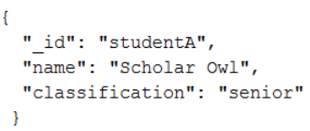
80
B.2.2 JSON Object
A JSON object is a set of unordered name-value pairs. It is represented a pair of curly brackets
surrounded by zero or more name-vale pairs. The name portion of the name-value pair is always a string value.
The value portion is one of the supported JSON data types. A sample JSON object is shown below.
Figure 25 JSON Object example
B.2.3 Value
A value in JSON must be one of the following data types:
• string
A string is a sequence of Unicode characters which are wrapped in quotation marks [13]. The string
allows for the use of the backslash control character.
• number
A number in JSON is represented in base 10 [13] A number can contain a decimal and/or an exponent 10
ten (the exponent is denoted with the symbol e). It is important to note that infinity and NaN are not
supported.
• object
The object is a valid JSON object
• array
An array is a collection of order values.

81
• boolean
A Boolean in JSON is represent as either true or false
• null
A null value is specified with the of the word null.
B.2.4 Array
Arrays in JSON are collection of ordered values which must be one of the supported value data types.
Each array in JSON is enclosed in a set of brackets ([]), and each value inside of the brackets is delimited with a
comma. An example of a JSON array is shown below.
Figure 26. JSON Array example
B.3 XML Schema Definition Language
B.3.1 What is XML Schema Definition Language?
XML Schema Definition Language (XSD) is a language that offers the means for describing the structure
and constraining documents [41]. The language itself is created with XML. XSD creates a type system for XML
[28, 37], which is necessary because XML is a text-based language. XSD provides the constructs for specifying
valid constraints and structures [31] in addition to the type system provision. The language also provides
considerable improvements over its predecessor, the Document Type Definition (DTD). The DTD is used to
define the legal structure of an XML document. DTD originates from the Structured Generalized Markup
Language. Some ways in which DTD differs from XSD are:
• DTD has limited data typing capabilities

82
• DTD is not XML-based
• DTD does not support namespaces
B.3.2 XSD Features
B.3.2.1 Data Typing
XSD gives the XML the ability to be richly data typed. The schema definition language provides the
following built-in data types [28]:
Table 3 XSD data types
Data Type Description
string a sequence of characters
boolean represents true or false
decimal represents a decimal
float single-precision 32-bit floating-point number
double double-precision 64-bit floating-point number
duration a length of time
dateTime a specific instance of time with the format (CCYY-MM-
DDThh:mm:ss)
• CC – century
• YY – year
• DD – day
• T – date/time separator
• hh – hours
• mm – minutes
• ss – seconds
time instance of time that reoccurs each day with format
(hh:mm:ss.sss)
date a calendar date with format (CCYY-MM-DD)
gYearMonth Gregorian month in a specific Gregorian year
gYear Gregorian year
gDay Gregorian day
gMonth Gregorian month
hexBinary hex-encoded binary data
base64Binary Base64-encoded arbitrary data
anyURI URI as specified in RFC 2396
QName qualified name
NOTATION a notation attribute that is composed of QNames
XSD does not limit the data modeler or programmer to the primitive types. It also provides the constructs to
create user-defined data types.

B.3.2.2 Complex Elements
In XML, a complex element is an element that is composed of one or more elements and/or attributes.
Complex elements can be categorized into one of the following categories
•
contains both elements and text
• contains only text
• contains only elements
• contains empty elements
An example of a complex element is shown below.
Figure 27 XML sample document
The same co
mplex element defined in XSD is shown below.
Figure 28 XSD sample document
In XML, a complex element is an element that is composed of one or more elements and/or attributes.
Complex elements can be categorized into one of the following categories
[42]:
contains both elements and text
An example of a complex element is shown below.
mplex element defined in XSD is shown below.
83
In XML, a complex element is an element that is composed of one or more elements and/or attributes.

84
B.3.2.3 XSD Restrictions
The XML schema definition language uses restrictions (for attributes) and facets (for elements) to
enforce data specifications (acceptable values and format). Some of the restrictions are shown below:
enumerati
• fractionDigits
This constraint is used to specify the number of allowed decimal places.
• Length
The constraint specifies the number of characters or list item allowed.
B.3.2.4 XSD Indicators
Indicators are used in XSD define how the elements will be used in the XML document. XSD provides for
the following seven indicators [34]:
Table 4 XSD indicators
Indicator Name Description
All The All indicator is an order indicator. It is used to
specify that the parent element’s children can appear in
any order, and must occur only one time.
Choice The Choice indicator is an order indicator. It is used to
specify that only one of the parent element’s child
elements can occur.
Sequence The Sequence indicator is an order indicator. It is used
to specify that the parent element’s children must appear
in the specified order.
maxOccurs The maxOccurs indicator is an occurrence indicator. It
specifies the maximum number of occurrences allowed
for an element.
minOccurs The minOccurs indicator is an occurrence indicator. It
specifies the minimum number of occurrences allowed
for an element.
group The group indicator is used to create a set of related
elements.
attributeGroup The attributeGroup indicator is used to create a set of
related attributes.
85

86
APPENDIX C
SOURCE CODE
C.1 Mongo Data Import Statements
87
APPENDIX D
EXPERIMENTAL DATA
D.1 Schema.tables
[
{
"_id": "PT_Project",
"_idDataType": "VARCHAR(100)",
"tableName": "PT_Project",
"tableNameDataType": "VARCHAR(50)",
"useGlobalColumns": true
},
{
"_id": "PT_ContractChangeOrder",
"_idDataType": "VARCHAR(100)",
"tableName": "PT_ContractChangeOrder",
"tableNameDataType": "VARCHAR(50)",
"useGlobalColumns": true
},
{
"_id": "PT_ContractChangeOrderMemo",
"_idDataType": "VARCHAR(100)",
"tableName": "PT_ContractChangeOrderMemo",
"tableNameDataType": "VARCHAR(50)",
"useGlobalColumns": true
},
{
"_id": "PT_Drawing",
88
"_idDataType": "VARCHAR(100)",
"tableName": "PT_Drawing",
"tableNameDataType": "VARCHAR(50)",
"useGlobalColumns": true
},
{
"_id": "SPT_Contractor",
"_idDataType": "VARCHAR(100)",
"tableName": "SPT_Contractor",
"tableNameDataType": "VARCHAR(50)",
"useGlobalColumns": true
}
]
D.2 Schema.table.global.columns
[
{
"globalColumnName": "_id",
"globalColumNameDataType": "VARCHAR(100)"
}
]
D.3 Schema.table.containers
[
{
"_id": "OC_Documents",
"_idTDataType": "VARCHAR(100)",
"containerID": "OC_Documents",
"containerIDDataType": "VARCHAR(100)",
89
"required": false,
"parentContainerID": "parentContainer",
"parentContainerIDDataType": "VARCHAR(100)",
"parentContainerRequired": false,
"parentTableID": "PT_Project",
"parentTableIDDataType": "VARCHAR(100)",
"childTables": {
"required": false,
"minOccurrences": "1",
"maxOccurrences": "UNBOUNDED",
"childTableID": "childTable",
"childTableIDDataType": "VARCHAR(100)"
}
}
]
D.4 Schema.table.columns.simple
[
{
"_id": "PTCS_Project_ProjectCode",
"_idDataType": "VARCHAR(100)",
"tableID": "PT_Project",
"tableIDDataType": "VARCHAR(100)",
"columnName": "PTCS_Project_ProjectCode",
"columnNameDataType": "VARCHAR(100)",
"columnValueDataType" : "VARCHAR(4)",
"required": true,
"referencedTableID": "referencedTableID",
"referencedTableIDDataType": "VARCHAR(100)",
90
"referencedColumnName": "referencedColumnName",
"referencedColumnNameDataType": "VARCHAR(100)",
"referencedColumnRequired": false
},
{
"_id": "PTCS_Project_ProjectNo",
"_idDataType": "VARCHAR(100)",
"tableID": "PT_Project",
"tableIDDataType": "VARCHAR(100)",
"columnName": "PTCS_Project_ProjectNo",
"columnNameDataType": "VARCHAR(100)",
"columnValueDataType" : "VARCHAR(4)",
"required": true,
"referencedTableID": "referencedTableID",
"referencedTableIDDataType": "VARCHAR(100)",
"referencedColumnName": "referencedColumnName",
"referencedColumnNameDataType": "VARCHAR(100)",
"referencedColumnRequired": false
},
{
"_id": "PTCS_ContractChangeOrder_DocumentIdentifier",
"_idDataType": "VARCHAR(100)",
"tableID": "PT_ContractChangeOrder",
"tableIDDataType": "VARCHAR(100)",
"columnName": "PTCS_ContractChangeOrder_DocumentIdentifier",
"columnNameDataType": "VARCHAR(100)",
"columnValueDataType" : "VARCHAR(30)",
"required": true,
"referencedTableID": "referencedTableID",
91
"referencedTableIDDataType": "VARCHAR(100)",
"referencedColumnName": "referencedColumnName",
"referencedColumnNameDataType": "VARCHAR(100)",
"referencedColumnRequired": false
},
{
"_id": "PTCS_ContractChangeOrder_DocumentName",
"_idDataType": "VARCHAR(100)",
"tableID": "PT_ContractChangeOrder",
"tableIDDataType": "VARCHAR(100)",
"columnName": "PTCS_ContractChangeOrder_DocumentName",
"columnNameDataType": "VARCHAR(100)",
"columnValueDataType" : "VARCHAR(30)",
"required": true,
"referencedTableID": "referencedTableID",
"referencedTableIDDataType": "VARCHAR(100)",
"referencedColumnName": "referencedColumnName",
"referencedColumnNameDataType": "VARCHAR(100)",
"referencedColumnRequired": false
},
{
"_id": "PTCS_ContractChangeOrder_FilePath",
"_idDataType": "VARCHAR(100)",
"tableID": "PT_ContractChangeOrder",
"tableIDDataType": "VARCHAR(100)",
"columnName": "PTCS_ContractChangeOrder_FilePath",
"columnNameDataType": "VARCHAR(100)",
"columnValueDataType" : "VARCHAR(100)",
"required": true,
92
"referencedTableID": "referencedTableID",
"referencedTableIDDataType": "VARCHAR(100)",
"referencedColumnName": "referencedColumnName",
"referencedColumnNameDataType": "VARCHAR(100)",
"referencedColumnRequired": false
},
{
"_id": "PTCS_ContractChangeOrder_ContractModificationTitle",
"_idDataType": "VARCHAR(100)",
"tableID": "PT_ContractChangeOrder",
"tableIDDataType": "VARCHAR(100)",
"columnName": "PTCS_ContractChangeOrder_ContractModificationTitle",
"columnNameDataType": "VARCHAR(100)",
"columnValueDataType" : "VARCHAR(100)",
"required": true,
"referencedTableID": "referencedTableID",
"referencedTableIDDataType": "VARCHAR(100)",
"referencedColumnName": "referencedColumnName",
"referencedColumnNameDataType": "VARCHAR(100)",
"referencedColumnRequired": false
},
{
"_id": "PTCS_ContractChangeOrder_MemoText",
"_idDataType": "VARCHAR(100)",
"tableID": "PT_ContractChangeOrder",
"tableIDDataType": "VARCHAR(100)",
"columnName": "PTCS_ContractChangeOrder_MemoText",
"columnNameDataType": "VARCHAR(100)",
"columnValueDataType" : "VARCHAR(2000)",
93
"required": true,
"referencedTableID": "referencedTableID",
"referencedTableIDDataType": "VARCHAR(100)",
"referencedColumnName": "referencedColumnName",
"referencedColumnNameDataType": "VARCHAR(100)",
"referencedColumnRequired": false
},
{
"_id": "PTCS_ContractChangeOrder_ContractorID",
"_idDataType": "VARCHAR(100)",
"tableID": "PT_ContractChangeOrder",
"tableIDDataType": "VARCHAR(100)",
"columnName": "PTCS_ContractChangeOrder_ContractorID",
"columnNameDataType": "VARCHAR(15)",
"columnValueDataType" : "INTEGER",
"required": true,
"referencedTableID": "referencedTableID",
"referencedTableIDDataType": "VARCHAR(100)",
"referencedColumnName": "referencedColumnName",
"referencedColumnNameDataType": "VARCHAR(100)",
"referencedColumnRequired": false
},
{
"_id": "PTCS_ContractChangeOrder_LOCATION",
"_idDataType": "VARCHAR(100)",
"tableID": "PT_ContractChangeOrder",
"tableIDDataType": "VARCHAR(100)",
"columnName": "PTCS_ContractChangeOrder_LOCATION",
"columnNameDataType": "VARCHAR(100)",
94
"columnValueDataType" : "VARCHAR(10)",
"required": true,
"referencedTableID": "referencedTableID",
"referencedTableIDDataType": "VARCHAR(100)",
"referencedColumnName": "referencedColumnName",
"referencedColumnNameDataType": "VARCHAR(100)",
"referencedColumnRequired": false
},
{
"_id": "PTCS_ContractChangeOrder_CostChangeIndicator",
"_idDataType": "VARCHAR(100)",
"tableID": "PT_ContractChangeOrder",
"tableIDDataType": "VARCHAR(100)",
"columnName": "PTCS_ContractChangeOrder_CostChangeIndicator",
"columnNameDataType": "VARCHAR(100)",
"columnValueDataType" : "CHAR(1)",
"required": true,
"referencedTableID": "referencedTableID",
"referencedTableIDDataType": "VARCHAR(100)",
"referencedColumnName": "referencedColumnName",
"referencedColumnNameDataType": "VARCHAR(100)",
"referencedColumnRequired": false
},
{
"_id": "PTCS_ContractChangeOrder_CostChangeAmount",
"_idDataType": "VARCHAR(100)",
"tableID": "PT_ContractChangeOrder",
"tableIDDataType": "VARCHAR(100)",
"columnName": "PTCS_ContractChangeOrder_CostChangeAmount",
95
"columnNameDataType": "VARCHAR(100)",
"columnValueDataType" : "DECIMAL(10,2)",
"required": true,
"referencedTableID": "referencedTableID",
"referencedTableIDDataType": "VARCHAR(100)",
"referencedColumnName": "referencedColumnName",
"referencedColumnNameDataType": "VARCHAR(100)",
"referencedColumnRequired": false
},
{
"_id": "PTCS_ContractChangeOrder_NumOfDaysToCompleteWork",
"_idDataType": "VARCHAR(100)",
"tableID": "PT_ContractChangeOrder",
"tableIDDataType": "VARCHAR(100)",
"columnName": "PTCS_ContractChangeOrder_NumOfDaysToCompleteWork",
"columnNameDataType": "VARCHAR(100)",
"columnValueDataType" : "INTEGER",
"required": true,
"referencedTableID": "referencedTableID",
"referencedTableIDDataType": "VARCHAR(100)",
"referencedColumnName": "referencedColumnName",
"referencedColumnNameDataType": "VARCHAR(100)",
"referencedColumnRequired": false
},
{
"_id": "PTCS_ContractChangeOrder_ProjectOrderNo",
"_idDataType": "VARCHAR(100)",
"tableID": "PT_ContractChangeOrder",
"tableIDDataType": "VARCHAR(100)",
96
"columnName": "PTCS_ContractChangeOrder_ProjectOrderNo",
"columnNameDataType": "VARCHAR(100)",
"columnValueDataType" : "VARCHAR(9)",
"required": true,
"referencedTableID": "referencedTableID",
"referencedTableIDDataType": "VARCHAR(100)",
"referencedColumnName": "referencedColumnName",
"referencedColumnNameDataType": "VARCHAR(100)",
"referencedColumnRequired": false
},
{
"_id": "PTCS_ContractChangeOrderMemo_ProjectCode",
"_idDataType": "VARCHAR(100)",
"tableID": "PT_ContractChangeOrderMemo",
"tableIDDataType": "VARCHAR(100)",
"columnName": "PTCS_ContractChangeOrderMemo_ProjectCode",
"columnNameDataType": "VARCHAR(100)",
"columnValueDataType" : "VARCHAR(4)",
"required": true,
"referencedTableID": "referencedTableID",
"referencedTableIDDataType": "VARCHAR(100)",
"referencedColumnName": "referencedColumnName",
"referencedColumnNameDataType": "VARCHAR(100)",
"referencedColumnRequired": false
},
{
"_id": "PTCS_ContractChangeOrderMemo_ProjectNo",
"_idDataType": "VARCHAR(100)",
"tableID": "PT_ContractChangeOrderMemo",
97
"tableIDDataType": "VARCHAR(100)",
"columnName": "PTCS_ContractChangeOrderMemo_ProjectNo",
"columnNameDataType": "VARCHAR(100)",
"columnValueDataType" : "VARCHAR(4)",
"required": true,
"referencedTableID": "referencedTableID",
"referencedTableIDDataType": "VARCHAR(100)",
"referencedColumnName": "referencedColumnName",
"referencedColumnNameDataType": "VARCHAR(100)",
"referencedColumnRequired": false
},
{
"_id": "PTCS_ContractChangeOrderMemo_DocumentIdentifier",
"_idDataType": "VARCHAR(100)",
"tableID": "PT_ContractChangeOrderMemo",
"tableIDDataType": "VARCHAR(100)",
"columnName": "PTCS_ContractChangeOrderMemo_DocumentIdentifier",
"columnNameDataType": "VARCHAR(100)",
"columnValueDataType" : "VARCHAR(30)",
"required": true,
"referencedTableID": "referencedTableID",
"referencedTableIDDataType": "VARCHAR(100)",
"referencedColumnName": "referencedColumnName",
"referencedColumnNameDataType": "VARCHAR(100)",
"referencedColumnRequired": false
},
{
"_id": "PTCS_ContractChangeOrderMemo_DocumentName",
"_idDataType": "VARCHAR(100)",
98
"tableID": "PT_ContractChangeOrderMemo",
"tableIDDataType": "VARCHAR(100)",
"columnName": "PTCS_ContractChangeOrderMemo_DocumentName",
"columnNameDataType": "VARCHAR(100)",
"columnValueDataType" : "VARCHAR(30)",
"required": true,
"referencedTableID": "referencedTableID",
"referencedTableIDDataType": "VARCHAR(100)",
"referencedColumnName": "referencedColumnName",
"referencedColumnNameDataType": "VARCHAR(100)",
"referencedColumnRequired": false
},
{
"_id": "PTCS_ContractChangeOrderMemo_FilePath",
"_idDataType": "VARCHAR(100)",
"tableID": "PT_ContractChangeOrderMemo",
"tableIDDataType": "VARCHAR(100)",
"columnName": "PTCS_ContractChangeOrderMemo_FilePath",
"columnNameDataType": "VARCHAR(100)",
"columnValueDataType" : "VARCHAR(100)",
"required": true,
"referencedTableID": "referencedTableID",
"referencedTableIDDataType": "VARCHAR(100)",
"referencedColumnName": "referencedColumnName",
"referencedColumnNameDataType": "VARCHAR(100)",
"referencedColumnRequired": false
},
{
"_id": "PTCS_ContractChangeOrderMemo_MemoDate",
99
"_idDataType": "VARCHAR(100)",
"tableID": "PT_ContractChangeOrderMemo",
"tableIDDataType": "VARCHAR(100)",
"columnName": "PTCS_ContractChangeOrderMemo_MemoDate",
"columnNameDataType": "VARCHAR(100)",
"columnValueDataType" : "DATE",
"required": true,
"referencedTableID": "referencedTableID",
"referencedTableIDDataType": "VARCHAR(100)",
"referencedColumnName": "referencedColumnName",
"referencedColumnNameDataType": "VARCHAR(100)",
"referencedColumnRequired": false
},
{
"_id": "PTCS_ContractChangeOrderMemo_Audience",
"_idDataType": "VARCHAR(100)",
"tableID": "PT_ContractChangeOrderMemo",
"tableIDDataType": "VARCHAR(100)",
"columnName": "PTCS_ContractChangeOrderMemo_Audience",
"columnNameDataType": "VARCHAR(100)",
"columnValueDataType" : "VARCHAR(50)",
"required": true,
"referencedTableID": "referencedTableID",
"referencedTableIDDataType": "VARCHAR(100)",
"referencedColumnName": "referencedColumnName",
"referencedColumnNameDataType": "VARCHAR(100)",
"referencedColumnRequired": false
},
{
100
"_id": "PTCS_ContractChangeOrderMemo_Sender",
"_idDataType": "VARCHAR(100)",
"tableID": "PT_ContractChangeOrderMemo",
"tableIDDataType": "VARCHAR(100)",
"columnName": "PTCS_ContractChangeOrderMemo_Sender",
"columnNameDataType": "VARCHAR(100)",
"columnValueDataType" : "VARCHAR(50)",
"required": true,
"referencedTableID": "referencedTableID",
"referencedTableIDDataType": "VARCHAR(100)",
"referencedColumnName": "referencedColumnName",
"referencedColumnNameDataType": "VARCHAR(100)",
"referencedColumnRequired": false
},
{
"_id": "PTCS_ContractChangeOrderMemo_Subject",
"_idDataType": "VARCHAR(100)",
"tableID": "PT_ContractChangeOrderMemo",
"tableIDDataType": "VARCHAR(100)",
"columnName": "PTCS_ContractChangeOrderMemo_Subject",
"columnNameDataType": "VARCHAR(100)",
"columnValueDataType" : "VARCHAR(100)",
"required": true,
"referencedTableID": "referencedTableID",
"referencedTableIDDataType": "VARCHAR(100)",
"referencedColumnName": "referencedColumnName",
"referencedColumnNameDataType": "VARCHAR(100)",
"referencedColumnRequired": false
},
101
{
"_id": "PTCS_ContractChangeOrderMemo_InReferenceTo",
"_idDataType": "VARCHAR(100)",
"tableID": "PT_ContractChangeOrderMemo",
"tableIDDataType": "VARCHAR(100)",
"columnName": "PTCS_ContractChangeOrderMemo_InReferenceTo",
"columnNameDataType": "VARCHAR(100)",
"columnValueDataType" : "VARCHAR(100)",
"required": true,
"referencedTableID": "referencedTableID",
"referencedTableIDDataType": "VARCHAR(100)",
"referencedColumnName": "referencedColumnName",
"referencedColumnNameDataType": "VARCHAR(100)",
"referencedColumnRequired": false
},
{
"_id": "PTCS_ContractChangeOrderMemo_MemoBody",
"_idDataType": "VARCHAR(100)",
"tableID": "PT_ContractChangeOrderMemo",
"tableIDDataType": "VARCHAR(100)",
"columnName": "PTCS_ContractChangeOrderMemo_MemoBody",
"columnNameDataType": "VARCHAR(100)",
"columnValueDataType" : "VARCHAR(2000)",
"required": true,
"referencedTableID": "referencedTableID",
"referencedTableIDDataType": "VARCHAR(100)",
"referencedColumnName": "referencedColumnName",
"referencedColumnNameDataType": "VARCHAR(100)",
"referencedColumnRequired": false
102
},
{
"_id": "PTCS_Drawing_DocumentIdentifier",
"_idDataType": "VARCHAR(100)",
"tableID": "PT_Drawing",
"tableIDDataType": "VARCHAR(100)",
"columnName": "PTCS_Drawing_DocumentIdentifier",
"columnNameDataType": "VARCHAR(100)",
"columnValueDataType" : "VARCHAR(30)",
"required": true,
"referencedTableID": "referencedTableID",
"referencedTableIDDataType": "VARCHAR(100)",
"referencedColumnName": "referencedColumnName",
"referencedColumnNameDataType": "VARCHAR(100)",
"referencedColumnRequired": false
},
{
"_id": "PTCS_Drawing_ProjectCode",
"_idDataType": "VARCHAR(100)",
"tableID": "PT_Drawing",
"tableIDDataType": "VARCHAR(100)",
"columnName": "PTCS_Drawing_ProjectCode",
"columnNameDataType": "VARCHAR(100)",
"columnValueDataType" : "VARCHAR(4)",
"required": true,
"referencedTableID": "referencedTableID",
"referencedTableIDDataType": "VARCHAR(100)",
"referencedColumnName": "referencedColumnName",
"referencedColumnNameDataType": "VARCHAR(100)",
103
"referencedColumnRequired": false
},
{
"_id": "PTCS_Drawing_ProjectNo",
"_idDataType": "VARCHAR(100)",
"tableID": "PT_Drawing",
"tableIDDataType": "VARCHAR(100)",
"columnName": "PTCS_Drawing_ProjectNo",
"columnNameDataType": "VARCHAR(100)",
"columnValueDataType" : "VARCHAR(4)",
"required": true,
"referencedTableID": "referencedTableID",
"referencedTableIDDataType": "VARCHAR(100)",
"referencedColumnName": "referencedColumnName",
"referencedColumnNameDataType": "VARCHAR(100)",
"referencedColumnRequired": false
},
{
"_id": "PTCS_Drawing_DocumentName",
"_idDataType": "VARCHAR(100)",
"tableID": "PT_Drawing",
"tableIDDataType": "VARCHAR(100)",
"columnName": "PTCS_Drawing_DocumentName",
"columnNameDataType": "VARCHAR(100)",
"columnValueDataType" : "VARCHAR(30)",
"required": true,
"referencedTableID": "referencedTableID",
"referencedTableIDDataType": "VARCHAR(100)",
"referencedColumnName": "referencedColumnName",
104
"referencedColumnNameDataType": "VARCHAR(100)",
"referencedColumnRequired": false
},
{
"_id": "PTCS_Drawing_FilePath",
"_idDataType": "VARCHAR(100)",
"tableID": "PT_Drawing",
"tableIDDataType": "VARCHAR(100)",
"columnName": "PTCS_Drawing_FilePath",
"columnNameDataType": "VARCHAR(100)",
"columnValueDataType" : "VARCHAR(100)",
"required": true,
"referencedTableID": "referencedTableID",
"referencedTableIDDataType": "VARCHAR(100)",
"referencedColumnName": "referencedColumnName",
"referencedColumnNameDataType": "VARCHAR(100)",
"referencedColumnRequired": false
},
{
"_id": "PTCS_Drawing_SheetNumber",
"_idDataType": "VARCHAR(100)",
"tableID": "PT_Drawing",
"tableIDDataType": "VARCHAR(100)",
"columnName": "PTCS_Drawing_SheetNumber",
"columnNameDataType": "VARCHAR(100)",
"columnValueDataType" : "INTEGER",
"required": true,
"referencedTableID": "referencedTableID",
"referencedTableIDDataType": "VARCHAR(100)",
105
"referencedColumnName": "referencedColumnName",
"referencedColumnNameDataType": "VARCHAR(100)",
"referencedColumnRequired": false
},
{
"_id": "PTCS_Drawing_HorizontalScale",
"_idDataType": "VARCHAR(100)",
"tableID": "PT_Drawing",
"tableIDDataType": "VARCHAR(100)",
"columnName": "PTCS_Drawing_HorizontalScale",
"columnNameDataType": "VARCHAR(100)",
"columnValueDataType" : "VARCHAR(15)",
"required": true,
"referencedTableID": "referencedTableID",
"referencedTableIDDataType": "VARCHAR(100)",
"referencedColumnName": "referencedColumnName",
"referencedColumnNameDataType": "VARCHAR(100)",
"referencedColumnRequired": false
},
{
"_id": "PTCS_Drawing_VerticalScale",
"_idDataType": "VARCHAR(100)",
"tableID": "PT_Drawing",
"tableIDDataType": "VARCHAR(100)",
"columnName": "PTCS_Drawing_VerticalScale",
"columnNameDataType": "VARCHAR(100)",
"columnValueDataType" : "VARCHAR(15)",
"required": true,
"referencedTableID": "referencedTableID",
106
"referencedTableIDDataType": "VARCHAR(100)",
"referencedColumnName": "referencedColumnName",
"referencedColumnNameDataType": "VARCHAR(100)",
"referencedColumnRequired": false
},
{
"_id": "PTCS_Contractor_ContractorID",
"_idDataType": "VARCHAR(100)",
"tableID": "SPT_Contractor",
"tableIDDataType": "VARCHAR(100)",
"columnName": "PTCS_Contractor_ContractorID",
"columnNameDataType": "VARCHAR(100)",
"columnValueDataType" : "VARCHAR(15)",
"required": true,
"referencedTableID": "referencedTableID",
"referencedTableIDDataType": "VARCHAR(100)",
"referencedColumnName": "referencedColumnName",
"referencedColumnNameDataType": "VARCHAR(100)",
"referencedColumnRequired": false
},
{
"_id": "PTCS_Contractor_ContractorStreetAddress",
"_idDataType": "VARCHAR(100)",
"tableID": "SPT_Contractor",
"tableIDDataType": "VARCHAR(100)",
"columnName": "PTCS_Contractor_ContractorStreetAddress",
"columnNameDataType": "VARCHAR(100)",
"columnValueDataType" : "VARCHAR(50)",
"required": true,
107
"referencedTableID": "referencedTableID",
"referencedTableIDDataType": "VARCHAR(100)",
"referencedColumnName": "referencedColumnName",
"referencedColumnNameDataType": "VARCHAR(100)",
"referencedColumnRequired": false
},
{
"_id": "PTCS_Contractor_ContractorCity",
"_idDataType": "VARCHAR(100)",
"tableID": "SPT_Contractor",
"tableIDDataType": "VARCHAR(100)",
"columnName": "PTCS_Contractor_ContractorCity",
"columnNameDataType": "VARCHAR(100)",
"columnValueDataType" : "VARCHAR(50)",
"required": true,
"referencedTableID": "referencedTableID",
"referencedTableIDDataType": "VARCHAR(100)",
"referencedColumnName": "referencedColumnName",
"referencedColumnNameDataType": "VARCHAR(100)",
"referencedColumnRequired": false
},
{
"_id": "PTCS_Contractor_ContractorState",
"_idDataType": "VARCHAR(100)",
"tableID": "SPT_Contractor",
"tableIDDataType": "VARCHAR(100)",
"columnName": "PTCS_Contractor_ContractorState",
"columnNameDataType": "VARCHAR(100)",
"columnValueDataType" : "CHAR(2)",
108
"required": true,
"referencedTableID": "referencedTableID",
"referencedTableIDDataType": "VARCHAR(100)",
"referencedColumnName": "referencedColumnName",
"referencedColumnNameDataType": "VARCHAR(100)",
"referencedColumnRequired": false
},
{
"_id": "PTCS_Contractor_ContractorZipCode",
"_idDataType": "VARCHAR(100)",
"tableID": "SPT_Contractor",
"tableIDDataType": "VARCHAR(100)",
"columnName": "PTCS_Contractor_ContractorZipCode",
"columnNameDataType": "VARCHAR(100)",
"columnValueDataType" : "CHAR(5)",
"required": true,
"referencedTableID": "referencedTableID",
"referencedTableIDDataType": "VARCHAR(100)",
"referencedColumnName": "referencedColumnName",
"referencedColumnNameDataType": "VARCHAR(100)",
"referencedColumnRequired": false
}
]
D.5 Schema.table.columns.complex
[
{
"_id": "PTCC_Drawing_DrawingSignoff",
"_idDataType": "VARCHAR(100)",
109
"tableID": "PT_Drawing",
"tableIDDataType": "VARCHAR(100)",
"columnName": "PTCC_Drawing_DrawingSignoff",
"columnNameDataType": "VARCHAR(100)",
"required": false,
"minOccurrences": "0",
"maxOccurrences": "UNBOUNDED",
"parentColumn": {
"required": false,
"parentColumnID": "parentColumnID",
"parentColumnIDDataType": "VARCHAR(100)"
},
"columnAttributes": [
{
"codeEnforcedPrimaryKey": true,
"columnAttributeName": "phase",
"columnAttributeNameDataType": "VARCHAR(100)",
"columnAttributeDataType": "VARCHAR(20)",
"columnAttributeRequired": true,
"referencedTableID": "referencedTableID",
"referencedTableIDDataType": "VARCHAR(100)",
"referencedColumnName": "referencedColumnName",
"referencedColumnNameDataType": "VARCHAR(100)",
"referencedColumnRequired": false
},
{
"codeEnforcedPrimaryKey": false,
"columnAttributeName": "designerInitials",
"columnAttributeNameDataType": "VARCHAR(100)",
110
"columnAttributeDataType": "VARCHAR(3)",
"columnAttributeRequired": true,
"referencedTableID": "referencedTableID",
"referencedTableIDDataType": "VARCHAR(100)",
"referencedColumnName": "referencedColumnName",
"referencedColumnNameDataType": "VARCHAR(100)",
"referencedColumnRequired": false
},
{
"codeEnforcedPrimaryKey": false,
"columnAttributeName": "checkerName",
"columnAttributeNameDataType": "VARCHAR(100)",
"columnAttributeDataType": "VARCHAR(50)",
"columnAttributeRequired": true,
"referencedTableID": "referencedTableID",
"referencedTableIDDataType": "VARCHAR(100)",
"referencedColumnName": "referencedColumnName",
"referencedColumnNameDataType": "VARCHAR(100)",
"referencedColumnRequired": false
},
{
"codeEnforcedPrimaryKey": false,
"columnAttributeName": "checkedDate",
"columnAttributeNameDataType": "VARCHAR(100)",
"columnAttributeDataType": "DATE",
"columnAttributeRequired": true,
"referencedTableID": "referencedTableID",
"referencedTableIDDataType": "VARCHAR(100)",
"referencedColumnName": "referencedColumnName",
111
"referencedColumnNameDataType": "VARCHAR(100)",
"referencedColumnRequired": false
},
{
"codeEnforcedPrimaryKey": false,
"columnAttributeName": "designedDate",
"columnAttributeNameDataType": "VARCHAR(100)",
"columnAttributeDataType": "DATE",
"columnAttributeRequired": true,
"referencedTableID": "referencedTableID",
"referencedTableIDDataType": "VARCHAR(100)",
"referencedColumnName": "referencedColumnName",
"referencedColumnNameDataType": "VARCHAR(100)",
"referencedColumnRequired": false
}
],
"childComplexColumns": {
"required": false,
"minOccurrences": "0",
"maxOccurrences": "UNBOUNDED",
"childComplexColumnID": "childColumnID",
"childComplexColumnIDDataType": "VARCHAR(100)"
}
},
{
"_id": "PTCC_Drawing_RevisionHistory",
"_idDataType": "VARCHAR(100)",
"tableID": "PT_Drawing",
"tableIDDataType": "VARCHAR(100)",
112
"columnName": "PTCC_Drawing_RevisionHistory",
"columnNameDataType": "VARCHAR(100)",
"required": false,
"minOccurrences": "0",
"maxOccurrences": "UNBOUNDED",
"parentColumn": {
"required": false,
"parentColumnID": "parentColumnID",
"parentColumnIDDataType": "VARCHAR(100)"
},
"columnAttributes": [
{
"codeEnforcedPrimaryKey": true,
"columnAttributeName": "revisionDate",
"columnAttributeNameDataType": "VARCHAR(100)",
"columnAttributeDataType": "DATE",
"columnAttributeRequired": true,
"referencedTableID": "referencedTableID",
"referencedTableIDDataType": "VARCHAR(100)",
"referencedColumnName": "referencedColumnName",
"referencedColumnNameDataType": "VARCHAR(100)",
"referencedColumnRequired": false
},
{
"codeEnforcedPrimaryKey": false,
"columnAttributeName": "comments",
"columnAttributeNameDataType": "VARCHAR(100)",
"columnAttributeDataType": "VARCHAR(200)",
"columnAttributeRequired": true,
113
"referencedTableID": "referencedTableID",
"referencedTableIDDataType": "VARCHAR(100)",
"referencedColumnName": "referencedColumnName",
"referencedColumnNameDataType": "VARCHAR(100)",
"referencedColumnRequired": false
},
{
"codeEnforcedPrimaryKey": false,
"columnAttributeName": "revisedByInitials",
"columnAttributeNameDataType": "VARCHAR(100)",
"columnAttributeDataType": "VARCHAR(3)",
"columnAttributeRequired": true,
"referencedTableID": "referencedTableID",
"referencedTableIDDataType": "VARCHAR(100)",
"referencedColumnName": "referencedColumnName",
"referencedColumnNameDataType": "VARCHAR(100)",
"referencedColumnRequired": false
}
],
"childComplexColumns": {
"required": false,
"minOccurrences": "0",
"maxOccurrences": "UNBOUNDED",
"childComplexColumnID": "childColumnID",
"childComplexColumnIDDataType": "VARCHAR(100)"
}
},
{
"_id": "PTCC_Drawing_DrawingIndex",
114
"_idDataType": "VARCHAR(100)",
"tableID": "PT_Drawing",
"tableIDDataType": "VARCHAR(100)",
"columnName": "PTCC_Drawing_DrawingIndex",
"columnNameDataType": "VARCHAR(100)",
"required": false,
"minOccurrences": "0",
"maxOccurrences": "UNBOUNDED",
"parentColumn": {
"required": false,
"parentColumnID": "parentColumnID",
"parentColumnIDDataType": "VARCHAR(100)"
},
"columnAttributes": [
{
"codeEnforcedPrimaryKey": true,
"columnAttributeName": "drawingIndexIdentifier",
"columnAttributeNameDataType": "VARCHAR(100)",
"columnAttributeDataType": "VARCHAR(20)",
"columnAttributeRequired": true,
"referencedTableID": "referencedTableID",
"referencedTableIDDataType": "VARCHAR(100)",
"referencedColumnName": "referencedColumnName",
"referencedColumnNameDataType": "VARCHAR(100)",
"referencedColumnRequired": false
},
{
"codeEnforcedPrimaryKey": false,
"columnAttributeName": "designerName",
115
"columnAttributeNameDataType": "VARCHAR(100)",
"columnAttributeDataType": "VARCHAR(50)",
"columnAttributeRequired": true,
"referencedTableID": "referencedTableID",
"referencedTableIDDataType": "VARCHAR(100)",
"referencedColumnName": "referencedColumnName",
"referencedColumnNameDataType": "VARCHAR(100)",
"referencedColumnRequired": false
},
{
"codeEnforcedPrimaryKey": false,
"columnAttributeName": "detailerName",
"columnAttributeNameDataType": "VARCHAR(100)",
"columnAttributeDataType": "VARCHAR(50)",
"columnAttributeRequired": true,
"referencedTableID": "referencedTableID",
"referencedTableIDDataType": "VARCHAR(100)",
"referencedColumnName": "referencedColumnName",
"referencedColumnNameDataType": "VARCHAR(100)",
"referencedColumnRequired": false
},
{
"codeEnforcedPrimaryKey": false,
"columnAttributeName": "sheetSubset",
"columnAttributeNameDataType": "VARCHAR(100)",
"columnAttributeDataType": "VARCHAR(20)",
"columnAttributeRequired": true,
"referencedTableID": "referencedTableID",
"referencedTableIDDataType": "VARCHAR(100)",
116
"referencedColumnName": "referencedColumnName",
"referencedColumnNameDataType": "VARCHAR(100)",
"referencedColumnRequired": false
},
{
"codeEnforcedPrimaryKey": false,
"columnAttributeName": "subsetSheets",
"columnAttributeNameDataType": "VARCHAR(100)",
"columnAttributeDataType": "INTEGER",
"columnAttributeRequired": true,
"referencedTableID": "referencedTableID",
"referencedTableIDDataType": "VARCHAR(100)",
"referencedColumnName": "referencedColumnName",
"referencedColumnNameDataType": "VARCHAR(100)",
"referencedColumnRequired": false
},
{
"codeEnforcedPrimaryKey": false,
"columnAttributeName": "structureNumberStart",
"columnAttributeNameDataType": "VARCHAR(100)",
"columnAttributeDataType": "CHAR(7)",
"columnAttributeRequired": true,
"referencedTableID": "referencedTableID",
"referencedTableIDDataType": "VARCHAR(100)",
"referencedColumnName": "referencedColumnName",
"referencedColumnNameDataType": "VARCHAR(100)",
"referencedColumnRequired": false
},
{
117
"codeEnforcedPrimaryKey": false,
"columnAttributeName": "structureNumberEnd",
"columnAttributeNameDataType": "VARCHAR(100)",
"columnAttributeDataType": "CHAR(7)",
"columnAttributeRequired": true,
"referencedTableID": "referencedTableID",
"referencedTableIDDataType": "VARCHAR(100)",
"referencedColumnName": "referencedColumnName",
"referencedColumnNameDataType": "VARCHAR(100)",
"referencedColumnRequired": false
}
],
"childComplexColumns": {
"required": false,
"minOccurrences": "0",
"maxOccurrences": "UNBOUNDED",
"childComplexColumnID": "childColumnID",
"childComplexColumnIDDataType": "VARCHAR(100)"
}
},
{
"_id": "PTCC_ContractChangeOrder_LineItem",
"_idDataType": "VARCHAR(100)",
"tableID": "PT_ContractChangeOrder",
"tableIDDataType": "VARCHAR(100)",
"columnName": "PTCC_ContractChangeOrder_LineItem",
"columnNameDataType": "VARCHAR(100)",
"required": false,
"minOccurrences": "0",
118
"maxOccurrences": "UNBOUNDED",
"parentColumn": {
"required": false,
"parentColumnID": "parentColumnID",
"parentColumnIDDataType": "VARCHAR(100)"
},
"columnAttributes": [
{
"codeEnforcedPrimaryKey": true,
"columnAttributeName": "lineItemIdentifier",
"columnAttributeNameDataType": "VARCHAR(100)",
"columnAttributeDataType": "VARCHAR(15)",
"columnAttributeRequired": true,
"referencedTableID": "referencedTableID",
"referencedTableIDDataType": "VARCHAR(100)",
"referencedColumnName": "referencedColumnName",
"referencedColumnNameDataType": "VARCHAR(100)",
"referencedColumnRequired": false
},
{
"codeEnforcedPrimaryKey": false,
"columnAttributeName": "itemDescription",
"columnAttributeNameDataType": "VARCHAR(100)",
"columnAttributeDataType": "VARCHAR(50)",
"columnAttributeRequired": true,
"referencedTableID": "referencedTableID",
"referencedTableIDDataType": "VARCHAR(100)",
"referencedColumnName": "referencedColumnName",
"referencedColumnNameDataType": "VARCHAR(100)",
119
"referencedColumnRequired": false
},
{
"codeEnforcedPrimaryKey": false,
"columnAttributeName": "unitOfMeasure",
"columnAttributeNameDataType": "VARCHAR(100)",
"columnAttributeDataType": "VARCHAR(10)",
"columnAttributeRequired": true,
"referencedTableID": "referencedTableID",
"referencedTableIDDataType": "VARCHAR(100)",
"referencedColumnName": "referencedColumnName",
"referencedColumnNameDataType": "VARCHAR(100)",
"referencedColumnRequired": false
},
{
"codeEnforcedPrimaryKey": false,
"columnAttributeName": "previousQuantity",
"columnAttributeNameDataType": "VARCHAR(100)",
"columnAttributeDataType": "DECIMAL(8,2)",
"columnAttributeRequired": true,
"referencedTableID": "referencedTableID",
"referencedTableIDDataType": "VARCHAR(100)",
"referencedColumnName": "referencedColumnName",
"referencedColumnNameDataType": "VARCHAR(100)",
"referencedColumnRequired": false
},
{
"codeEnforcedPrimaryKey": false,
"columnAttributeName": "addedQuantity",
120
"columnAttributeNameDataType": "VARCHAR(100)",
"columnAttributeDataType": "DECIMAL(8,2)",
"columnAttributeRequired": true,
"referencedTableID": "referencedTableID",
"referencedTableIDDataType": "VARCHAR(100)",
"referencedColumnName": "referencedColumnName",
"referencedColumnNameDataType": "VARCHAR(100)",
"referencedColumnRequired": false
},
{
"codeEnforcedPrimaryKey": false,
"columnAttributeName": "revisionPlanQuantity",
"columnAttributeNameDataType": "VARCHAR(100)",
"columnAttributeDataType": "DECIMAL(8,2)",
"columnAttributeRequired": true,
"referencedTableID": "referencedTableID",
"referencedTableIDDataType": "VARCHAR(100)",
"referencedColumnName": "referencedColumnName",
"referencedColumnNameDataType": "VARCHAR(100)",
"referencedColumnRequired": false
},
{
"codeEnforcedPrimaryKey": false,
"columnAttributeName": "unitPrice",
"columnAttributeNameDataType": "VARCHAR(100)",
"columnAttributeDataType": "DECIMAL(8,2)",
"columnAttributeRequired": true,
"referencedTableID": "referencedTableID",
"referencedTableIDDataType": "VARCHAR(100)",
121
"referencedColumnName": "referencedColumnName",
"referencedColumnNameDataType": "VARCHAR(100)",
"referencedColumnRequired": false
},
{
"codeEnforcedPrimaryKey": false,
"columnAttributeName": "changeType",
"columnAttributeNameDataType": "VARCHAR(100)",
"columnAttributeDataType": "CHAR(1)",
"columnAttributeRequired": true,
"referencedTableID": "referencedTableID",
"referencedTableIDDataType": "VARCHAR(100)",
"referencedColumnName": "referencedColumnName",
"referencedColumnNameDataType": "VARCHAR(100)",
"referencedColumnRequired": false
}
],
"childComplexColumns": {
"required": false,
"minOccurrences": "0",
"maxOccurrences": "UNBOUNDED",
"childComplexColumnID": "childColumnID",
"childComplexColumnIDDataType": "VARCHAR(100)"
}
},
{
"_id": "PTCC_ContractChangeOrder_Authorization",
"_idDataType": "VARCHAR(100)",
"tableID": "PT_ContractChangeOrder",
122
"tableIDDataType": "VARCHAR(100)",
"columnName": "PTCC_ContractChangeOrder_Authorization",
"columnNameDataType": "VARCHAR(100)",
"required": false,
"minOccurrences": "0",
"maxOccurrences": "UNBOUNDED",
"parentColumn": {
"required": false,
"parentColumnID": "parentColumnID",
"parentColumnIDDataType": "VARCHAR(100)"
},
"columnAttributes": [
{
"codeEnforcedPrimaryKey": true,
"columnAttributeName": "authorizationIdentifier",
"columnAttributeNameDataType": "VARCHAR(100)",
"columnAttributeDataType": "VARCHAR(15)",
"columnAttributeRequired": true,
"referencedTableID": "referencedTableID",
"referencedTableIDDataType": "VARCHAR(100)",
"referencedColumnName": "referencedColumnName",
"referencedColumnNameDataType": "VARCHAR(100)",
"referencedColumnRequired": false
},
{
"codeEnforcedPrimaryKey": false,
"columnAttributeName": "roleName",
"columnAttributeNameDataType": "VARCHAR(100)",
"columnAttributeDataType": "VARCHAR(50)",
123
"columnAttributeRequired": true,
"referencedTableID": "referencedTableID",
"referencedTableIDDataType": "VARCHAR(100)",
"referencedColumnName": "referencedColumnName",
"referencedColumnNameDataType": "VARCHAR(100)",
"referencedColumnRequired": false
},
{
"codeEnforcedPrimaryKey": false,
"columnAttributeName": "authorizerName",
"columnAttributeNameDataType": "VARCHAR(100)",
"columnAttributeDataType": "VARCHAR(50)",
"columnAttributeRequired": true,
"referencedTableID": "referencedTableID",
"referencedTableIDDataType": "VARCHAR(100)",
"referencedColumnName": "referencedColumnName",
"referencedColumnNameDataType": "VARCHAR(100)",
"referencedColumnRequired": false
},
{
"codeEnforcedPrimaryKey": false,
"columnAttributeName": "authorizationDate",
"columnAttributeNameDataType": "VARCHAR(100)",
"columnAttributeDataType": "DATE",
"columnAttributeRequired": true,
"referencedTableID": "referencedTableID",
"referencedTableIDDataType": "VARCHAR(100)",
"referencedColumnName": "referencedColumnName",
"referencedColumnNameDataType": "VARCHAR(100)",
124
"referencedColumnRequired": false
}
],
"childComplexColumns": {
"required": false,
"minOccurrences": "0",
"maxOccurrences": "UNBOUNDED",
"childComplexColumnID": "childColumnID",
"childComplexColumnIDDataType": "VARCHAR(100)"
}
}
]
D.6 PT_Project
[
{
"_id": "Project-1",
"tableID": "PT_Project",
"PTCS_Project_ProjectCode": "PRJ1",
"PTCS_Project_ProjectNo": "0001",
"OC_Documents": {
"childTables": [
{
"childTable": "ChangeOrder-1"
},
{
"childTable": "DRAW-1"
}
]
125
}
}
]
D.7 PT_Drawing
[
{
"_id": "DRAW-1",
"PTCS_Drawing_DocumentIdentifier": "DRAW-1",
"PTCS_Drawing_ProjectCode": "PRJ1",
"PTCS_Drawing_ProjectNo": "0001",
"PTCS_Drawing_SheetNumber": 202,
"PTCS_Drawing_HorizontalScale": "NTS",
"PTCS_Drawing_VerticalScale": "As Noted",
"PTCS_Drawing_DocumentName": "Sheet_B-INDEX-1.dgn",
"PTCS_Drawing_FilePath": "\\drawings",
"PTCC_Drawing_RevisionHistory": {
"columnAttributes": [
{
"revisionDate": "11/1/2002",
"comments": "Added the bridge support structures.",
"revisedByInitials": "JBB"
},
{
"revisionDate": "11/5/2002",
"comments": "Removed the second pillar from the west side.",
"revisedByInitials": "JBB"
},
{
126
"revisionDate": "12/1/2002",
"comments": "Changed the direction of the cross beams on second level.",
"revisedByInitials": "GRA"
}
]
},
"PTCC_Drawing_DrawingSignoff": {
"columnAttributes": [
{
"phase": "Design",
"checkerName": "Phil Brown",
"checkedDate": "11/6/2002",
"designerInitials": "JBB",
"designedDate": "11/5/2002"
},
{
"phase": "Detail",
"checkerName": "Alice Smitherson",
"checkedDate": "12/20/2002",
"designerInitials": "JBB",
"designedDate": "11/5/2002"
},
{
"phase": "Design II",
"checkerName": "Phil Brown",
"checkedDate": "12/31/2002",
"designerInitials": "ARB",
"designedDate": "12/22/2002"
}
127
]
},
"PTCC_Drawing_DrawingIndex": {
"columnAttributes": [
{
"designerName": "Jeff Blank",
"detailerName": "Bailey Smith",
"sheetSubset": "Bridge",
"subsetSheets": 2,
"structureNumberStart": "1-01-01",
"structureNumberEnd": "4-04-04"
}
]
}
}
]
D.8 PT_ContractChangeOrderMemo
[
{
"PTCS_ContractChangeOrderMemo_DocumentIdentifier": "MEMO-1",
"PTCS_ContractChangeOrderMemo_DocumentName": "Route 111 Memo 1",
"PTCS_ContractChangeOrderMemo_FilePath": "\\memo",
"PTCS_ContractChangeOrderMemo_ProjectCode": "PRJ1",
"PTCS_ContractChangeOrderMemo_ProjectNo": "0001",
"PTCS_ContractChangeOrderMemo_MemoDate": "10/16/2001",
"PTCS_ContractChangeOrderMemo_Audience": "Resident Engineer or Program Engineer",
"PTCS_ContractChangeOrderMemo_Sender": "Project Engineer",
128
"PTCS_ContractChangeOrderMemo_Subject": "Contract Modification Order #11, Right-of-Way
Agreement-Fence Change",
"PTCS_ContractChangeOrderMemo_InReferenceTo": "11111 /NH 66-063 Route 66 - East",
"PTCS_ContractChangeOrderMemo_MemoBody": "The Right-of-way Agreement with the owners of Parcel
46 required that Fence Combination Wire be placed between Right-of-Way Point 165 and Right-of-Way
Point 166."
},
{
"PTCS_ContractChangeOrderMemo_DocumentIdentifier": "MEMO-2",
"PTCS_ContractChangeOrderMemo_DocumentName": "Route 111 Memo 2",
"PTCS_ContractChangeOrderMemo_FilePath": "\\memo",
"PTCS_ContractChangeOrderMemo_ProjectCode": "PRJ1",
"PTCS_ContractChangeOrderMemo_ProjectNo": "0001",
"PTCS_ContractChangeOrderMemo_MemoDate": "10/27/2001",
"PTCS_ContractChangeOrderMemo_Audience": "Resident Engineer",
"PTCS_ContractChangeOrderMemo_Sender": "Project Engineer",
"PTCS_ContractChangeOrderMemo_Subject": "Contract Modification Order #43, Concrete Change",
"PTCS_ContractChangeOrderMemo_InReferenceTo": "222 /NH 70-051 Route 66 - West",
"PTCS_ContractChangeOrderMemo_MemoBody": "The current concrete mixture must be change to
support the weight of the heavy machinery for the upcoming year's project."
}
]
D.9 SPT_Contractor
[
{
"_id": "CONTRACTOR-1",
"tableID": "SPT_Contractor",
"PTCS_Contractor_ContractorID": "CONTRACTOR-1",
"PTCS_Contractor_ContractorStreetAddress": "12 Allensmith Drive",
"PTCS_Contractor_ContractorCity": "Charlotte",
129
"PTCS_Contractor_ContractorState": "NC",
"PTCS_Contractor_ContractorZipCode": "28217"
}
]
D.10 PT_ContractChangeOrder
[
{
"_id": "ChangeOrder-1",
"PTCS_ContractChangeOrder_DocumentIdentifier": "ChangeOrder-1",
"PTCS_ContractChangeOrder_DocumentName": "ChangeOrder1.pdf",
"PTCS_ContractChangeOrder_FilePath": "\\changeorder",
"PTCS_ContractChangeOrder_ProjectCode": "PRJ1",
"PTCS_ContractChangeOrder_ProjectNo": "0001",
"PTCS_ContractChangeOrder_ContractModificationTitle": "Row Agreement-Fence Change",
"PTCS_ContractChangeOrder_MemoText": "Your contract is hereby modified to include Fence Wire
between Right-of-Way Point 165 and Righ-of-Way Point 166",
"PTCS_ContractChangeOrder_ContractorID": "CONTRACTOR-1",
"PTCS_ContractChangeOrder_Location": "Route 66-South",
"PTCS_ContractChangeOrder_ChangeOrderDate": "9/30/2002",
"PTCS_ContractChangeOrder_ProjectOrderNo": "NH 77-077",
"PTCS_ContractChangeOrder_CostChangeIndicator": "A",
"PTCS_ContractChangeOrder_CostChangeAmount": 3000.00,
"PTCS_ContractChangeOrder_NumOfDaysToCompleteWork": 4,
"PTCC_ContractChangeOrder_ContractChangeOrderAuthorization": {
"columnAttributes": [
{
"authorizationIdentifier": "AUTH-1",
"roleName": "FWHA Operations Engineer",
130
"authorizerName": "Bill R Pepper",
"authorizationDate": "10/1/2002"
},
{
"authorizationIdentifier": "AUTH-2",
"roleName": "Region Transportation Director",
"authorizerName": "Kelly J Brinkley",
"authorizationDate": "10/2/2002"
}
]
},
"PTCC_ContractChangeOrder_LineItem": {
"columnAttributes": [
{
"lineItemIdentifier": "LINEITEM-1",
"itemDescription": "607 Fence Comb Wire w/Metail Posts",
"unitOfMeasure": "LF",
"previousQuantity": 0.00,
"addedQuantity": 500.00,
"revisionPlanQuantity": 500.00,
"unitPrice": 6.00,
"changeType": "A"
},
{
"lineItemIdentifier": "LINEITEM-2",
"itemDescription": "607 Fence Comb Wire w/Metail Posts",
"unitOfMeasure": "LF",
"previousQuantity": 5000.00,
"addedQuantity": -500.00,
131
"revisionPlanQuantity": 4500.00,
"unitPrice": 5.50,
"changeType": "D"
}
]
}
}
]

132
APPENDIX E
SUPPLEMENTAL MODELING DIAGRAMS
Figure 29 Logical Model - PT_ContractChangeOrderMemo

133
Figure 30 Logical Model – PTCC_Drawing_DrawingIndex

Figure 31 Logical Model – OC diagram
134
