
Digital Scanner
Product Reference Guide
DS8178
MN-002752-14EN

DS8178 DIGITAL SCANNER
PRODUCT REFERENCE GUIDE
MN-002752-14EN
Revision A
August 2024

ii DS8178 Digital Scanner Product Reference Guide
ZEBRA and the stylized Zebra head are trademarks of Zebra Technologies Corporation, registered in many
jurisdictions worldwide. All other trademarks are the property of their respective owners. ©2024 Zebra
Technologies Corporation and/or its affiliates. All rights reserved.
Information in this document is subject to change without notice. The software described in this document is
furnished under a license agreement or nondisclosure agreement. The software may be used or copied only in
accordance with the terms of those agreements.
For further information regarding legal and proprietary statements, please go to:
SOFTWARE:zebra.com/linkoslegal
COPYRIGHTS:zebra.com/copyright
PATENTS:ip.zebra.com
WARRANTY:zebra.com/warranty
END USER LICENSE AGREEMENT: zebra.com/eula
Terms of Use
Proprietary Statement
This manual contains proprietary information of Zebra Technologies Corporation and its subsidiaries (“Zebra
Technologies”). It is intended solely for the information and use of parties operating and maintaining the
equipment described herein. Such proprietary information may not be used, reproduced, or disclosed to any
other parties for any other purpose without the express, written permission of Zebra Technologies.
Product Improvements
Continuous improvement of products is a policy of Zebra Technologies. All specifications and designs are
subject to change without notice.
Liability Disclaimer
Zebra Technologies takes steps to ensure that its published Engineering specifications and manuals are
correct; however, errors do occur. Zebra Technologies reserves the right to correct any such errors and
disclaims liability resulting therefrom.
Limitation of Liability
In no event shall Zebra Technologies or anyone else involved in the creation, production, or delivery of the
accompanying product (including hardware and software) be liable for any damages whatsoever (including,
without limitation, consequential damages including loss of business profits, business interruption, or loss of
business information) arising out of the use of, the results of use of, or inability to use such product, even if
Zebra Technologies has been advised of the possibility of such damages. Some jurisdictions do not allow the
exclusion or limitation of incidental or consequential damages, so the above limitation or exclusion may not
apply to you.

iii
Revision History
Changes to the original guide are listed below.
Change Date Description
MN-002752-14EN
Rev. A
08/2024
- Replaced FIPS 140-2 with FIPS 140-3.
MN-002752-13EN
Rev. A
12/2023 - Updated Table 14-2 IDC Symbologies
MN-002752-12EN
Rev. A
3/2023 - Updated Note description in Bluetooth Radio State (parameter # 1354)
- Added LED on Good Decode (parameter # 744)
- Updated Appendix A Standard Parameter Defaults Table A-1 for
Datalogic
Host Format (parameter # 2253), and Datalogic Supported Commands
(parameter # 2260)
- Added Product ID (PID) Type (parameter # 1281)
- Added Product ID (PID) Value (parameter # 1725)
- Added ECLevel (parameter # 1710)
- Added Transmit Codabar Check Digit (parameter # 704)
- Added Codabar Mod 16 Check Digit (parameter # 1784)
- Added Weblink QR (parameter 1947)
- Added Transmit EAN-8 Check Digit (parameter # 1881)
- Added Transmit EAN-13 Check Digit (parameter # 1882)
MN-002752-11EN
Rev. A
8/2021 Added CDC Host Variant.
MN-002752-10EN
Rev. A
6/2021 - Added the Very Low Power Setting barcode in Radio Output Power.
- Updated Defeat Virtual Tether Alarm.
MN-002752-09EN
Rev. A
4/2021 Added:
- AutoConfig (Scanner Cloning Through Cradle)
- Battery Charging User Indication Enhancement
- Datalogic Host Format
- Datalogic Supported Commands
- Datalogic RS232 variant to Table 10-2 and Table 10-3
- RS322 Host Datalogic Variant
- Virtual Tether
- Night Mode Silence Radio Beeper Indications
- Night Mode Silence Low Battery Beeper Indication
- Night Mode Silence Parameter Programming Beeper Indications
- Datalogic USB CDC Host Variant barcode.
Removed:
- Low Power Mode
- Provide Documentation Feedback
- "https://www".
Updated the Data Parsing section.
MN-002752-08EN
Rev. A
12/2020 - Removed Bluetooth Classic Bluetooth and/or Low Energy (Cradle Parameter
Only/ Cradle Host Only).
- Replaced offending terms.

iv DS8178 Digital Scanner Product Reference Guide
MN-002752-07EN
Rev. A
7/2020 - Split 123Scan chapter to Chapter 2 123Scan and Software Tools and
Chapter 16 Data Formatting: ADF, MDF, Preferred Symbol
- Updated Chapter 2 123Scan Requirements
- Updated the cleaners and disinfectant cleaners lists
- Updated Scanner SDK, Other Software Tools, and Videos
- Updated LED Indications and troubleshooting
- Added the USB Cert information in Table 4-2
- Added Data Parsing in Chapter 16
- Added Linked QR Mode (parameter #1847).
MN-002752-06
Rev. A
9/2019 Added PowerCap information.
MN-002752-05
Rev. A
6/2019 - Removed Simple COM Port Emulation.
- Removed Require and Suppress from OCR Template.
- Updated numeric keyboard cross references for OCR Check Digit Modulus
and OCR Quiet Zone.
- Updated OCR Template default and text.
- Updated Unsolicited Heartbeat Interval max value.
- Updated MSI Check Digits.
- Updated reference to Symbol Technologies under 1D Quiet Zone Level.
- Added 4th note to Autodiscriminate ISBT Concatenation.
MN-002752-04
Rev. A
10/2018 - Added Grid Matrix sample bar code.
- Updated approved cleaning agents for healthcare.
- Updated Secure Pharmaceutical to securPharm.
Change Date Description

v
MN-002752-03
Rev. A
7/2018 Updated:
- Zebra copyright statement.
- Troubleshooting.
- JIRA issues (top pixel address; Unsolicited Heartbeat Interval min/max
change).
- Modifier Characters Table E-3 (missing Malimark, GS1 Data Matrix, GS1
QR).
- MOD 10/MOD11 to MOD 11/MOD10.
- 123Scan chapter.
- OCR parameters 1766 & 1770.
- Digimarc bar codes and description; add to Appendix A default table.
- Defaults for Lamp Mode Control.
- Auto-reconnect feature.
- Pairing bar code format with STC info.
- Defaults for ISBT Concatenation.
- Values under bar codes for SSI baud rates: 230,400, 460,800, 921,600.
- CR8178-PC illustration and measurement callouts.
- Changed RSS Expanded to GS1 DataBar Expanded (Digimarc chapter).
- First row of table under Hands-free Decode Session Timeout.
- Changed ISBT 128 default to disable.
- Radio Output Power (parameter # 1324): The DS8178 uses a Bluetooth
Class 1 qualified and Class 2 capable radio.
- Bluetooth Radio, Linking, and Batch Operation: The DS8178 digital
scanner has a Bluetooth Class 1 qualified and Class 2 capable radio...
- Microsoft UWP USB changed to USB HID POS.
- Deleted OCR Common Fonts.
- Under Bluetooth Radio, Linking, and Batch Operation - Changed Bluetooth
Class 1 qualified and Class 2 capable radio range to 100 m / 330 ft.-
- Picklist Mode description.
- Relocated Pull Trigger Twice to Re-connect
- Night Mode
- Disable Image Cropping size
- Re-added
Timeout to Low Power Mode from Auto Aim
- Vibrate motor - HC only
- Moved Beep on <BEL> to User Prefs
- Lamp Mode - Deleted 10 min, 30 min, Always On
- Grid Matrix Inverse default to Regular Only
- Grid Matrix Mirror default to Regular Only
Added:
- Notes: When enabling ISBT Concatenation or Autodiscriminate ISBT.
- Concatenation set Code 128 security level to Level 2.
- Illumination Brightness parameter.
- Grid Matrix parameters.
- Symbol I, AIM ID, and AIM Code Modifier Character for Grid Matrix.
- OCR parameter: Enable/disable OCR common fonts; OCR Redundancy.
- GS1 DataBar variants.
- New GS1 DataBar variants sample bar codes.
- New Microsoft UWP USB (USB Host Type) host parameter.
- New troubleshooting row: LED blinks even if the pairing request was
canceled.
- Driver’s License Parsing parameter number.
- Secure Pharmaceutical and Secure Pharmaceutical Output Formatting
parameters.
- Re-pair on Double Trigger Press.
- Battery Attributes appendix.
- Scan Speed Analytics appendix.
- Febraban parameter.
- Battery Preservation Mode.
-
TGCS (IBM) USB Direct I/O Beep
Change Date Description

vi DS8178 Digital Scanner Product Reference Guide
MN-002752-02
Rev. A
03/2017 Updated:
- Sample bar codes appendix
- OCR chapter
- Uncropped image sizes
- Maintenance/Tech Specs chapter name
- Matrix 2 of 5 default
- Parameter name change: GS1 DataBar-14 to GS1 DataBar Omnidirectional
Added:
- Digimarc chapter
- Unpairing note
- Baud Rate 4800 (removed note: The digital scanner does not support baud
rates below 9600)
- Troubleshooting bar codes
- DotCode parameters
MN-002752-01
Rev. A
01/2017 Initial Release
Change Date Description

Revision History ................................................................................................................................. iii
About This Guide
Introduction ..................................................................................................................................... xxv
Configurations................................................................................................................................. xxv
Digital Scanner.......................................................................................................................... xxv
Cradles..................................................................................................................................... xxvi
Related Product Line Configurations ............................................................................................. xxvi
Cables...................................................................................................................................... xxvi
Chapter Descriptions .......................................................................................................................... xxvii
Notational Conventions................................................................................................................ xxviii
Related Documents ....................................................................................................................... xxix
Service Information ........................................................................................................................ xxix
Chapter 1: Getting Started
Introduction .................................................................................................................................... 1-1
Interfaces ....................................................................................................................................... 1-1
Unpacking ...................................................................................................................................... 1-1
DS8178 Features ........................................................................................................................... 1-2
Cradle Features ............................................................................................................................. 1-2
Standard Cradle ....................................................................................................................... 1-3
Presentation Cradle ................................................................................................................. 1-4
Connecting the Cradle ............................................................................................................. 1-4
Changing the Host Interface .................................................................................................... 1-4
Using a DC Power Supply ........................................................................................................ 1-5
Mounting the Cradle ................................................................................................................. 1-5
Using the Document Capture Stand .............................................................................................. 1-6
DS8178 Battery/PowerCap ............................................................................................................ 1-7
Charging the DS8178 Battery/PowerCap ................................................................................ 1-7
Recovering a Discharged Battery/PowerCap ........................................................................... 1-8
Shutting Off the Digital Scanner Battery or Capacitor .............................................................. 1-8
DS8178 Battery Statistics Capabilities ..................................................................................... 1-8
DS8178 PowerCap Statistics Capabilities ............................................................................... 1-9
Inserting the Battery/PowerCap ............................................................................................. 1-10
TABLE OF CONTENTS

viii DS8178 Digital Scanner Product Reference Guide
Removing the Battery/PowerCap ........................................................................................... 1-13
Inserting the Scanner in the Cradles ............................................................................................ 1-14
Sending Data to the Host Computer ............................................................................................ 1-15
Pairing .................................................................................................................................... 1-15
Lost Connection to Host ......................................................................................................... 1-15
Configuring the Scanner .............................................................................................................. 1-15
Radio Communications ................................................................................................................ 1-15
Accessories .................................................................................................................................. 1-16
Chapter 2: 123Scan and Software Tools
Introduction .................................................................................................................................... 2-1
123Scan ......................................................................................................................................... 2-1
Communication with 123Scan .................................................................................................. 2-2
123Scan Requirements ............................................................................................................ 2-2
123Scan Information ................................................................................................................ 2-2
Scanner SDK, Other Software Tools, and Videos ................................................................... 2-3
Scanner Control App ...................................................................................................................... 2-4
Scan-To-Connect (STC) Utility ...................................................................................................... 2-4
Chapter 3: Data Capture
Introduction .................................................................................................................................... 3-1
Beeper and LED Indications .......................................................................................................... 3-1
Digital Scanner Indications ....................................................................................................... 3-1
Cradle LED Indications ............................................................................................................ 3-4
Scanning ........................................................................................................................................ 3-7
Hand-Held Scanning ................................................................................................................ 3-7
Hands-Free Scanning .............................................................................................................. 3-7
Aiming with Digital Scanner ..................................................................................................... 3-8
Decode Ranges ........................................................................................................................... 3-10
Chapter 4: Maintenance, Troubleshooting, and Technical Specifications
Introduction .................................................................................................................................... 4-1
Maintenance .................................................................................................................................. 4-1
Known Harmful Ingredients ...................................................................................................... 4-2
Approved Cleaners for Standard DS8178 Digital Scanners and CR8178 Cradles .................. 4-2
Approved Disinfectant Cleaners for Healthcare Configurations of the DS8178 Digital Scanners
and CR8178 Cradles ........................................................................................................................... 4-2
Cleaning the Digital Scanner .................................................................................................... 4-3
Troubleshooting ............................................................................................................................. 4-5
Dump Scanner Parameters ...................................................................................................... 4-8
Send Versions .......................................................................................................................... 4-9
Report Software Version .................................................................................................... 4-9
Serial Number .................................................................................................................... 4-9
Manufacturing Information ................................................................................................. 4-9
Technical Specifications .............................................................................................................. 4-10
Cradle Signal Descriptions ........................................................................................................... 4-14

Table of Contents ix
Chapter 5: Radio Communications
Introduction .................................................................................................................................... 5-1
Setting Parameters ....................................................................................................................... 5-1
Scanning Sequence Examples ................................................................................................ 5-2
Errors While Scanning ............................................................................................................. 5-2
Radio Communications Parameter Defaults .................................................................................. 5-2
Wireless Beeper Definitions ........................................................................................................... 5-4
Radio Communication Host Types ................................................................................................ 5-4
Bluetooth Classic vs. Low Energy Bluetooth ............................................................................ 5-4
Cradle ....................................................................................................................................... 5-4
Human Interface Device (HID) Keyboard Emulation ................................................................ 5-6
Simple Serial Interface (SSI) .................................................................................................... 5-7
Serial Port Profile (SPP) ........................................................................................................... 5-9
Bluetooth Technology Profile Support ...................................................................................... 5-9
Central/Peripheral Set Up ........................................................................................................ 5-9
Central .............................................................................................................................. 5-10
Peripheral ......................................................................................................................... 5-10
Bluetooth Friendly Name ............................................................................................................. 5-10
Discoverable Mode ................................................................................................................ 5-11
Wi-Fi Friendly Mode ..................................................................................................................... 5-12
Notes ...................................................................................................................................... 5-12
Wi-Fi Friendly Channel Exclusion .......................................................................................... 5-12
Wi-Fi Channel Exclusion .................................................................................................. 5-12
Radio Output Power ..................................................................................................................... 5-14
Link Supervision Timeout ....................................................................................................... 5-15
Bluetooth Radio State .................................................................................................................. 5-16
HID Host Parameters ................................................................................................................... 5-17
HID Features for Apple iOS ................................................................................................... 5-17
HID Keyboard Keystroke Delay ............................................................................................. 5-18
HID CAPS Lock Override ....................................................................................................... 5-18
HID Ignore Unknown Characters ........................................................................................... 5-19
Emulate Keypad ..................................................................................................................... 5-19
Fast HID Keyboard ................................................................................................................. 5-20
Quick Keypad Emulation ........................................................................................................ 5-20
HID Keyboard FN1 Substitution ............................................................................................. 5-21
HID Function Key Mapping .................................................................................................... 5-21
Simulated Caps Lock ............................................................................................................. 5-22
Convert Case ......................................................................................................................... 5-22
Auto-Reconnect Feature .............................................................................................................. 5-23
Auto-Reconnect Option .......................................................................................................... 5-24
Reconnect Attempt Beep Feedback ...................................................................................... 5-25
Reconnect Attempt Interval .................................................................................................... 5-25
Sleep Between Attempts ........................................................................................................ 5-27
Number of Retry Attempts ...................................................................................................... 5-28
Out of Range Indicator ................................................................................................................. 5-29
Beep on Insertion ......................................................................................................................... 5-29
Digital Scanner(s) To Cradle Support .......................................................................................... 5-30
Modes of Operation ................................................................................................................ 5-30
Point-to-Point Communication ......................................................................................... 5-30
Multipoint-to-Point Communication .................................................................................. 5-30

x DS8178 Digital Scanner Product Reference Guide
Parameter Broadcast (Cradle Host Only) .............................................................................. 5-31
Pairing .................................................................................................................................... 5-31
Pairing Modes .................................................................................................................. 5-32
Lock Override ................................................................................................................... 5-32
Pairing Methods ..................................................................................................................... 5-33
Pull Trigger Twice to Re-connect ...................................................................................... 5-33
Unpairing .......................................................................................................................... 5-33
Toggle Pairing .................................................................................................................. 5-34
Pairing Bar Code Format Using the Scan-To-Connect (STC) Utility ...................................... 5-34
Connection Maintenance Interval ........................................................................................... 5-34
Considerations ................................................................................................................. 5-35
AutoConfig (Scanner Cloning Through Cradle) ..................................................................... 5-36
Cradle Configuration ........................................................................................................ 5-37
Batch Mode .................................................................................................................................. 5-37
Modes of Operation .......................................................................................................... 5-37
Persistent Batch Storage ............................................................................................................. 5-40
Page Button ................................................................................................................................. 5-40
Page Options ............................................................................................................................... 5-41
Page Mode ............................................................................................................................. 5-41
Page State Timeout ............................................................................................................... 5-41
Bluetooth Security ........................................................................................................................ 5-42
PIN Code ................................................................................................................................ 5-42
Variable PIN Code ............................................................................................................ 5-42
Bluetooth Security Levels ....................................................................................................... 5-44
Virtual Tether ............................................................................................................................... 5-45
Configuring the Alarm on the Scanner ................................................................................... 5-45
Audio Virtual Tether Alarm on Scanner ............................................................................ 5-46
LED Virtual Tether Alarm on Scanner ............................................................................... 5-46
Illumination Virtual Tether Alarm on Scanner ................................................................... 5-47
Haptic Virtual Tether Alarm on Scanner (DS8178-HC Only) ............................................ 5-47
Virtual Tether Alarm on the Cradle ......................................................................................... 5-48
Delay Before Virtual Alarm Activates ..................................................................................... 5-48
Virtual Tether Alarm Duration ................................................................................................. 5-49
Stopping the alarm ........................................................................................................... 5-49
Defeat Virtual Tether Alarm .................................................................................................... 5-50
Pause Virtual Tether Alarm Duration ..................................................................................... 5-50
Virtual Tether Alarm Considerations ................................................................................. 5-51
Bluetooth Radio, Linking, and Batch Operation ........................................................................... 5-52
Setting Up an iOS or Android Product To Work With The Digital Scanner ............................ 5-52
Chapter 6: User Preferences
Introduction .................................................................................................................................... 6-1
Scanning Sequence Examples ...................................................................................................... 6-2
Errors While Scanning ................................................................................................................... 6-2
User Preferences Parameter Defaults ........................................................................................... 6-2
Parameters .................................................................................................................................... 6-5
Default Parameters .................................................................................................................. 6-5
Parameter Bar Code Scanning ................................................................................................ 6-6
Beep After Good Decode ......................................................................................................... 6-6

Table of Contents xi
Beep on <BEL> ........................................................................................................................ 6-7
Direct Decode Indicator ............................................................................................................ 6-8
Beeper Volume ........................................................................................................................ 6-9
Beeper Tone .......................................................................................................................... 6-10
Beeper Duration ..................................................................................................................... 6-11
Suppress Power Up Beeps .................................................................................................... 6-11
LED on Good Decode ............................................................................................................ 6-12
Decode Pager Motor (DS8178-HC Only) ............................................................................... 6-12
Decode Pager Motor Duration (DS8178-HC Only) ................................................................ 6-13
Night Mode (DS8178-HC Only) .............................................................................................. 6-15
Night Mode Trigger ........................................................................................................... 6-16
Night Mode Toggle ........................................................................................................... 6-16
Night Mode Silence Radio Beeper Indications ................................................................. 6-17
Night Mode Silence Low Battery Beeper Indication ......................................................... 6-18
Night Mode Silence Parameter Programming Beeper Indications ................................... 6-19
Lamp Mode ............................................................................................................................ 6-21
Lamp Mode Control .......................................................................................................... 6-21
Lamp Mode Timeout ........................................................................................................ 6-22
Timeout to Low Power Mode from Auto Aim .......................................................................... 6-24
Battery Preservation Mode ..................................................................................................... 6-25
Hand-Held Trigger Mode ........................................................................................................ 6-26
Hands-Free Mode .................................................................................................................. 6-27
Hand-Held Decode Aiming Pattern ........................................................................................ 6-27
Hands-Free Decode Aiming Pattern ...................................................................................... 6-28
Picklist Mode .......................................................................................................................... 6-29
FIPS Mode ............................................................................................................................. 6-30
Continuous Bar Code Read ................................................................................................... 6-30
Unique Bar Code Reporting ................................................................................................... 6-31
Decode Session Timeout ....................................................................................................... 6-31
Hands-free Decode Session Timeout .................................................................................... 6-32
Timeout Between Decodes, Same Symbol ............................................................................ 6-33
Timeout Between Decodes, Different Symbols ...................................................................... 6-33
Triggered Timeout, Same Symbol ......................................................................................... 6-34
Decode Mirror Images (Data Matrix Only) ............................................................................. 6-35
Mobile Phone/Display Mode .................................................................................................. 6-36
PDF Prioritization ................................................................................................................... 6-37
PDF Prioritization Timeout ..................................................................................................... 6-38
Presentation Mode Field of View ........................................................................................... 6-38
Decoding Illumination ............................................................................................................. 6-39
Illumination Brightness ........................................................................................................... 6-39
Motion Tolerance (Hand-Held Trigger Modes Only) .............................................................. 6-40
Battery/PowerCap Threshold ................................................................................................. 6-41
Add an Enter Key ................................................................................................................... 6-42
Transmit Code ID Character .................................................................................................. 6-43
Prefix/Suffix Values ................................................................................................................ 6-44
Scan Data Transmission Format ............................................................................................ 6-45
FN1 Substitution Values ......................................................................................................... 6-46
Transmit “No Read” Message ................................................................................................ 6-47
Unsolicited Heartbeat Interval ................................................................................................ 6-48
securPharm Decoding ............................................................................................................ 6-49

xii DS8178 Digital Scanner Product Reference Guide
securPharm Output Formatting .............................................................................................. 6-50
Sample GS1 Format ........................................................................................................ 6-50
Sample IFA Format .......................................................................................................... 6-51
securPharm Output Formatting Bar Codes ...................................................................... 6-52
Battery Charging User Indication Enhancement .................................................................... 6-53
Chapter 7: Imaging Preferences
Introduction .................................................................................................................................... 7-1
Scanning Sequence Examples ...................................................................................................... 7-2
Errors While Scanning ................................................................................................................... 7-2
Imaging Preferences Parameter Defaults ...................................................................................... 7-2
Imaging Preferences ...................................................................................................................... 7-4
Operational Modes ................................................................................................................... 7-4
Decode Mode ..................................................................................................................... 7-4
Snapshot Mode .................................................................................................................. 7-4
Image Capture Illumination ...................................................................................................... 7-5
Image Capture Autoexposure .................................................................................................. 7-5
Fixed Exposure ........................................................................................................................ 7-6
Fixed Gain ................................................................................................................................ 7-6
Gain/Exposure Priority for Snapshot Mode .............................................................................. 7-7
Snapshot Mode Timeout .......................................................................................................... 7-8
Snapshot Aiming Pattern ......................................................................................................... 7-9
Silence Operational Mode Changes ........................................................................................ 7-9
Image Cropping ...................................................................................................................... 7-10
Crop to Pixel Addresses ......................................................................................................... 7-11
Image Size (Number of Pixels) .............................................................................................. 7-12
Image Brightness (Target White) ........................................................................................... 7-13
JPEG Image Options ............................................................................................................. 7-13
JPEG Target File Size ............................................................................................................ 7-14
JPEG Quality and Size Value ................................................................................................ 7-14
Image Enhancement .............................................................................................................. 7-15
Image File Format Selector .................................................................................................... 7-16
Image Rotation ....................................................................................................................... 7-17
Bits Per Pixel .......................................................................................................................... 7-18
Signature Capture .................................................................................................................. 7-19
Output File Format ........................................................................................................... 7-19
Signature Capture File Format Selector ................................................................................. 7-20
Signature Capture Bits Per Pixel ............................................................................................ 7-21
Signature Capture Width ........................................................................................................ 7-22
Signature Capture Height ....................................................................................................... 7-22
Signature Capture JPEG Quality ........................................................................................... 7-22
Chapter 8: USB Interface
Introduction .................................................................................................................................... 8-1
Connecting a USB Interface .......................................................................................................... 8-1
USB Parameter Defaults ................................................................................................................ 8-3
USB Host Parameters .................................................................................................................... 8-5
USB Device Type ..................................................................................................................... 8-5
CDC Host Variant ..................................................................................................................... 8-7

Table of Contents xiii
Symbol Native API (SNAPI) Status Handshaking .................................................................... 8-8
USB Keystroke Delay ............................................................................................................... 8-8
USB CAPS Lock Override ........................................................................................................ 8-9
USB Ignore Unknown Characters ............................................................................................ 8-9
USB Convert Unknown to Code 39 ........................................................................................ 8-10
Emulate Keypad ..................................................................................................................... 8-10
Emulate Keypad with Leading Zero ....................................................................................... 8-10
Quick Keypad Emulation ........................................................................................................ 8-11
USB Keyboard FN 1 Substitution ........................................................................................... 8-11
Function Key Mapping ........................................................................................................... 8-12
Simulated Caps Lock ............................................................................................................. 8-12
Convert Case ......................................................................................................................... 8-13
USB Static CDC ..................................................................................................................... 8-13
Optional USB Parameters ............................................................................................................ 8-14
TGCS (IBM) USB Direct I/O Beep ......................................................................................... 8-14
TGCS (IBM) USB Beep Directive ........................................................................................... 8-14
TGCS (IBM) USB Bar Code Configuration Directive ............................................................. 8-15
USB Polling Interval ............................................................................................................... 8-16
USB Fast HID ......................................................................................................................... 8-18
IBM Specification Version ...................................................................................................... 8-18
Product ID (PID) Type ............................................................................................................ 8-19
Product ID (PID) Value ........................................................................................................... 8-19
ECLevel .................................................................................................................................. 8-20
ASCII Character Sets for USB ..................................................................................................... 8-20
Chapter 9: SSI Interface
Introduction .................................................................................................................................... 9-1
Communications ............................................................................................................................ 9-1
SSI Transactions ............................................................................................................................ 9-3
General Data Transactions ...................................................................................................... 9-3
ACK/NAK Handshaking ..................................................................................................... 9-3
Transfer of Decode Data .......................................................................................................... 9-4
ACK/NAK Enabled and Packeted Data .............................................................................. 9-4
ACK/NAK Enabled and Unpacketed ASCII Data ............................................................... 9-4
ACK/NAK Disabled and Packeted DECODE_DATA .......................................................... 9-5
ACK/NAK Disabled and Unpacketed ASCII Data .............................................................. 9-5
Communication Summary .............................................................................................................. 9-5
RTS/CTS Lines ........................................................................................................................ 9-5
ACK/NAK Option ...................................................................................................................... 9-5
Number of Data Bits ................................................................................................................. 9-5
Serial Response Time-out ........................................................................................................ 9-6
Retries ...................................................................................................................................... 9-6
Baud Rate, Stop Bits, Parity, Response Time-out, ACK/NAK Handshake .............................. 9-6
Errors ....................................................................................................................................... 9-6
Things to Remember When Using SSI Communication ................................................................ 9-6
Using Time Delay to Low Power Mode with SSI ............................................................................ 9-7
Encapsulation of RSM Commands/Responses over SSI .............................................................. 9-8
Command Structure ................................................................................................................. 9-8
Response Structure ................................................................................................................. 9-8

xiv DS8178 Digital Scanner Product Reference Guide
Example Transaction ............................................................................................................... 9-9
Command from Host to Query Packet Size Supported by Device ..................................... 9-9
Response from Device with Packet Size Information ........................................................ 9-9
Command from Host to Retrieve Diagnostic Information ................................................... 9-9
Response from Device with Diagnostic Information ........................................................... 9-9
Simple Serial Interface Default Parameters ................................................................................. 9-10
SSI Host Parameters ................................................................................................................... 9-11
Select SSI Host ...................................................................................................................... 9-11
Baud Rate .............................................................................................................................. 9-12
Parity ...................................................................................................................................... 9-13
Check Parity ........................................................................................................................... 9-14
Stop Bits ................................................................................................................................. 9-14
Software Handshaking ........................................................................................................... 9-15
Host RTS Line State .............................................................................................................. 9-16
Decode Data Packet Format .................................................................................................. 9-16
Host Serial Response Time-out ............................................................................................. 9-17
Host Character Time-out ........................................................................................................ 9-18
Multipacket Option ................................................................................................................. 9-19
Interpacket Delay ................................................................................................................... 9-20
Event Reporting ........................................................................................................................... 9-21
Decode Event ......................................................................................................................... 9-21
Boot Up Event ........................................................................................................................ 9-22
Parameter Event .................................................................................................................... 9-22
Chapter 10: RS-232 Interface
Introduction .................................................................................................................................. 10-1
Connecting an RS-232 Interface .................................................................................................. 10-2
RS-232 Parameter Defaults ......................................................................................................... 10-3
RS-232 Host Parameters ............................................................................................................. 10-4
RS-232 Host Types ................................................................................................................ 10-7
Baud Rate .............................................................................................................................. 10-9
Parity .................................................................................................................................... 10-10
Stop Bit Select ...................................................................................................................... 10-11
Data Bits ............................................................................................................................... 10-11
Check Receive Errors .......................................................................................................... 10-12
Hardware Handshaking ........................................................................................................ 10-12
Software Handshaking ......................................................................................................... 10-14
Host Serial Response Time-out ........................................................................................... 10-16
RTS Line State ..................................................................................................................... 10-17
Beep on <BEL> .................................................................................................................... 10-17
Intercharacter Delay ............................................................................................................. 10-18
Nixdorf Beep/LED Options ................................................................................................... 10-19
Ignore Unknown Characters ................................................................................................ 10-19
Datalogic Host Format ......................................................................................................... 10-20
Datalogic Supported Commands ......................................................................................... 10-20
ASCII Character Set for RS-232 ................................................................................................ 10-21
Chapter 11: IBM 468X / 469X Interface
Introduction .................................................................................................................................. 11-1

Table of Contents xv
Connecting to an IBM 468X/469X Host ....................................................................................... 11-2
IBM Parameter Defaults ............................................................................................................... 11-3
IBM 468X/469X Host Parameters ................................................................................................ 11-4
Port Address .......................................................................................................................... 11-4
Convert Unknown to Code 39 ................................................................................................ 11-5
RS-485 Beep Directive ........................................................................................................... 11-5
RS-485 Bar Code Configuration Directive ............................................................................. 11-6
IBM-485 Specification Version ............................................................................................... 11-6
Chapter 12: Keyboard Wedge Interface
Introduction .................................................................................................................................. 12-1
Connecting a Keyboard Wedge Interface .................................................................................... 12-2
Keyboard Wedge Parameter Defaults ......................................................................................... 12-3
Keyboard Wedge Host Parameters ............................................................................................. 12-4
Keyboard Wedge Host Types ................................................................................................ 12-4
Ignore Unknown Characters .................................................................................................. 12-4
Keystroke Delay ..................................................................................................................... 12-5
Intra-Keystroke Delay ............................................................................................................. 12-5
Alternate Numeric Keypad Emulation .................................................................................... 12-6
Quick Keypad Emulation ........................................................................................................ 12-6
Simulated Caps Lock ............................................................................................................. 12-7
Caps Lock Override ............................................................................................................... 12-7
Convert Wedge Case ............................................................................................................. 12-8
Function Key Mapping ........................................................................................................... 12-8
FN1 Substitution ..................................................................................................................... 12-9
Send Make and Break ............................................................................................................ 12-9
Keyboard Maps .................................................................................................................... 12-10
ASCII Character Set for Keyboard Wedge ................................................................................ 12-10
Chapter 13: Symbologies
Introduction .................................................................................................................................. 13-1
Scanning Sequence Examples .................................................................................................... 13-1
Errors While Scanning ................................................................................................................. 13-2
Symbology Parameter Defaults ................................................................................................... 13-2
Enable/Disable All Code Types ................................................................................................... 13-8
UPC/EAN ..................................................................................................................................... 13-8
Enable/Disable UPC-A ........................................................................................................... 13-8
Enable/Disable UPC-E ........................................................................................................... 13-9
Enable/Disable UPC-E1 ......................................................................................................... 13-9
Enable/Disable EAN-8/JAN-8 .............................................................................................. 13-10
Enable/Disable EAN-13/JAN-13 .......................................................................................... 13-10
Enable/Disable Bookland EAN ............................................................................................. 13-11
Decode UPC/EAN/JAN Supplementals ............................................................................... 13-12
User-Programmable Supplementals .................................................................................... 13-15
UPC/EAN/JAN Supplemental Redundancy ......................................................................... 13-15
UPC/EAN/JAN Supplemental AIM ID Format ...................................................................... 13-16
UPC Reduced Quiet Zone ................................................................................................... 13-17
Transmit UPC-A Check Digit ................................................................................................ 13-17
Transmit UPC-E Check Digit ................................................................................................ 13-18

xvi DS8178 Digital Scanner Product Reference Guide
Transmit UPC-E1 Check Digit .............................................................................................. 13-18
Transmit EAN-8 Check Digit ................................................................................................ 13-19
Transmit EAN-13 Check Digit .............................................................................................. 13-19
UPC-A Preamble .................................................................................................................. 13-20
UPC-E Preamble .................................................................................................................. 13-21
UPC-E1 Preamble ................................................................................................................ 13-22
Convert UPC-E to UPC-A .................................................................................................... 13-23
Convert UPC-E1 to UPC-A .................................................................................................. 13-23
EAN-8/JAN-8 Extend ........................................................................................................... 13-24
Bookland ISBN Format ........................................................................................................ 13-24
UCC Coupon Extended Code .............................................................................................. 13-25
Coupon Report ..................................................................................................................... 13-25
ISSN EAN ............................................................................................................................ 13-26
Code 128 ................................................................................................................................... 13-26
Enable/Disable Code 128 .................................................................................................... 13-26
Set Lengths for Code 128 .................................................................................................... 13-27
Enable/Disable GS1-128 (formerly UCC/EAN-128) ............................................................. 13-29
Enable/Disable ISBT 128 ..................................................................................................... 13-29
ISBT Concatenation ............................................................................................................. 13-30
Check ISBT Table ................................................................................................................ 13-31
ISBT Concatenation Redundancy ........................................................................................ 13-31
Code 128 Security Level ...................................................................................................... 13-32
Code 128 Reduced Quiet Zone ........................................................................................... 13-33
Ignore Code 128 <FNC4> .................................................................................................... 13-33
Code 39 ..................................................................................................................................... 13-34
Enable/Disable Code 39 ...................................................................................................... 13-34
Enable/Disable Trioptic Code 39 .......................................................................................... 13-34
Convert Code 39 to Code 32 ............................................................................................... 13-35
Code 32 Prefix ..................................................................................................................... 13-35
Set Lengths for Code 39 ...................................................................................................... 13-36
Code 39 Check Digit Verification ......................................................................................... 13-37
Transmit Code 39 Check Digit ............................................................................................. 13-37
Code 39 Full ASCII Conversion ........................................................................................... 13-38
Code 39 Security Level ........................................................................................................ 13-39
Code 39 Reduced Quiet Zone ............................................................................................. 13-40
Code 93 ..................................................................................................................................... 13-40
Enable/Disable Code 93 ...................................................................................................... 13-40
Set Lengths for Code 93 ...................................................................................................... 13-41
Code 11 ..................................................................................................................................... 13-42
Code 11 ................................................................................................................................ 13-42
Set Lengths for Code 11 ...................................................................................................... 13-42
Code 11 Check Digit Verification ......................................................................................... 13-44
Interleaved 2 of 5 (ITF) .............................................................................................................. 13-45
Enable/Disable Interleaved 2 of 5 ........................................................................................ 13-45
Set Lengths for Interleaved 2 of 5 ........................................................................................ 13-45
I 2 of 5 Check Digit Verification ............................................................................................ 13-47
Convert I 2 of 5 to EAN-13 ................................................................................................... 13-48
Febraban .............................................................................................................................. 13-48
I 2 of 5 Security Level ........................................................................................................... 13-49
I 2 of 5 Reduced Quiet Zone ................................................................................................ 13-50

Table of Contents xvii
Discrete 2 of 5 (DTF) ................................................................................................................. 13-51
Enable/Disable Discrete 2 of 5 ............................................................................................. 13-51
Set Lengths for Discrete 2 of 5 ............................................................................................. 13-51
Codabar (NW - 7) ....................................................................................................................... 13-53
Enable/Disable Codabar ...................................................................................................... 13-53
Set Lengths for Codabar ...................................................................................................... 13-53
CLSI Editing ......................................................................................................................... 13-55
NOTIS Editing ...................................................................................................................... 13-55
Codabar Security Level ........................................................................................................ 13-56
Codabar Upper or Lower Case Start/Stop Characters Detection ........................................ 13-57
Codabar Mod 16 Check Digit ............................................................................................... 13-57
Transmit Codabar Check Digit ............................................................................................. 13-58
MSI ............................................................................................................................................. 13-58
Enable/Disable MSI .............................................................................................................. 13-58
Set Lengths for MSI ............................................................................................................. 13-59
MSI Check Digits .................................................................................................................. 13-60
Transmit MSI Check Digit(s) ................................................................................................ 13-61
MSI Check Digit Algorithm ................................................................................................... 13-61
MSI Reduced Quiet Zone ..................................................................................................... 13-62
Chinese 2 of 5 ............................................................................................................................ 13-63
Enable/Disable Chinese 2 of 5 ............................................................................................. 13-63
Matrix 2 of 5 ............................................................................................................................... 13-63
Enable/Disable Matrix 2 of 5 ................................................................................................ 13-63
Set Lengths for Matrix 2 of 5 ................................................................................................ 13-64
Matrix 2 of 5 Check Digit ...................................................................................................... 13-65
Transmit Matrix 2 of 5 Check Digit ....................................................................................... 13-65
Korean 3 of 5 ............................................................................................................................. 13-66
Enable/Disable Korean 3 of 5 .............................................................................................. 13-66
Inverse 1D .................................................................................................................................. 13-67
GS1 DataBar .............................................................................................................................. 13-68
GS1 DataBar Omnidirectional (formerly GS1 DataBar-14), GS1 DataBar Truncated, GS1 DataBar
Stacked, GS1 DataBar Stacked Omnidirectional ............................................................................. 13-68
GS1 DataBar Limited ........................................................................................................... 13-68
GS1 DataBar Expanded, GS1 DataBar Expanded Stacked ................................................ 13-69
Convert GS1 DataBar to UPC/EAN ..................................................................................... 13-69
GS1 DataBar Limited Margin Check .................................................................................... 13-70
GS1 DataBar Security Level ................................................................................................ 13-71
Composite .................................................................................................................................. 13-72
Composite CC-C .................................................................................................................. 13-72
Composite CC-A/B ............................................................................................................... 13-72
Composite TLC-39 ............................................................................................................... 13-73
Composite Inverse ............................................................................................................... 13-73
UPC Composite Mode ......................................................................................................... 13-74
Composite Beep Mode ......................................................................................................... 13-75
GS1-128 Emulation Mode for UCC/EAN Composite Codes ................................................ 13-75
2D Symbologies ......................................................................................................................... 13-76
Enable/Disable PDF417 ....................................................................................................... 13-76
Enable/Disable MicroPDF417 .............................................................................................. 13-76
Code 128 Emulation ............................................................................................................. 13-77
Data Matrix ........................................................................................................................... 13-77

xviii DS8178 Digital Scanner Product Reference Guide
GS1 Data Matrix ................................................................................................................... 13-78
Data Matrix Inverse .............................................................................................................. 13-79
Maxicode .............................................................................................................................. 13-79
QR Code .............................................................................................................................. 13-80
GS1 QR ................................................................................................................................ 13-80
MicroQR ............................................................................................................................... 13-81
Weblink QR .......................................................................................................................... 13-81
Linked QR Mode .................................................................................................................. 13-82
Aztec .................................................................................................................................... 13-83
Aztec Inverse ....................................................................................................................... 13-83
Han Xin ................................................................................................................................ 13-84
Han Xin Inverse .................................................................................................................... 13-84
Grid Matrix ............................................................................................................................ 13-85
Grid Matrix Inverse ............................................................................................................... 13-85
Grid Matrix Mirror ................................................................................................................. 13-86
DotCode ............................................................................................................................... 13-86
DotCode Inverse .................................................................................................................. 13-87
DotCode Mirrored ................................................................................................................. 13-88
DotCode Prioritize ................................................................................................................ 13-89
Postal Codes .............................................................................................................................. 13-89
US Postnet ........................................................................................................................... 13-89
US Planet ............................................................................................................................. 13-90
Transmit US Postal Check Digit ........................................................................................... 13-90
UK Postal ............................................................................................................................. 13-91
Transmit UK Postal Check Digit ........................................................................................... 13-91
Japan Postal ........................................................................................................................ 13-92
Australia Post ....................................................................................................................... 13-92
Australia Post Format ........................................................................................................... 13-93
Netherlands KIX Code ........................................................................................................ 13-94
USPS 4CB/One Code/Intelligent Mail .................................................................................. 13-94
UPU FICS Postal ................................................................................................................. 13-95
Mailmark ............................................................................................................................... 13-95
Symbology-Specific Security Levels .......................................................................................... 13-96
Redundancy Level ............................................................................................................... 13-96
Redundancy Level 1 ...................................................................................................... 13-96
Redundancy Level 2 ...................................................................................................... 13-96
Redundancy Level 3 ...................................................................................................... 13-96
Redundancy Level 4 ...................................................................................................... 13-97
Security Level ....................................................................................................................... 13-98
1D Quiet Zone Level ............................................................................................................ 13-99
Intercharacter Gap Size ..................................................................................................... 13-100
Report Version ......................................................................................................................... 13-100
Macro PDF Features ................................................................................................................ 13-101
Flush Macro Buffer ............................................................................................................. 13-101
Abort Macro PDF Entry ...................................................................................................... 13-101
Chapter 14: Intelligent Document Capture
Introduction .................................................................................................................................. 14-1
The IDC Process .......................................................................................................................... 14-1

Table of Contents xix
Bar Code Acceptance Test .................................................................................................... 14-2
Capture Region Determination ............................................................................................... 14-2
IDC Operating Mode = Anchored ..................................................................................... 14-2
IDC Operating Mode = Free-Form or Linked ................................................................... 14-3
Image Post Processing .......................................................................................................... 14-3
Data Transmission ................................................................................................................. 14-3
PC Application and Programming Support .................................................................................. 14-3
Parameters .................................................................................................................................. 14-4
IDC Operating Mode .............................................................................................................. 14-5
IDC Symbology ...................................................................................................................... 14-6
IDC X Coordinate ................................................................................................................... 14-7
IDC Y Coordinate ................................................................................................................... 14-7
IDC Width ............................................................................................................................... 14-8
IDC Height .............................................................................................................................. 14-8
IDC Aspect ............................................................................................................................. 14-9
IDC File Format Selector ........................................................................................................ 14-9
IDC Bits Per Pixel ................................................................................................................. 14-10
IDC JPEG Quality ................................................................................................................ 14-10
IDC Find Box Outline ........................................................................................................... 14-11
IDC Minimum Text Length ................................................................................................... 14-11
IDC Maximum Text Length .................................................................................................. 14-12
IDC Captured Image Brighten .............................................................................................. 14-12
IDC Captured Image Sharpen .............................................................................................. 14-13
IDC Border Type .................................................................................................................. 14-14
IDC Delay Time .................................................................................................................... 14-15
IDC Zoom Limit .................................................................................................................... 14-15
IDC Maximum Rotation ........................................................................................................ 14-16
Quick Start ................................................................................................................................. 14-16
Sample IDC Setup ............................................................................................................... 14-16
IDC Demonstrations ............................................................................................................. 14-17
Anchored Mode Demo ................................................................................................... 14-17
Free-Form Mode Demo .................................................................................................. 14-18
Linked Mode Demo ........................................................................................................ 14-18
Other Suggestions ............................................................................................................... 14-18
Quick Start Form .................................................................................................................. 14-19
Chapter 15: Digimarc Bar code
Introduction .................................................................................................................................. 15-1
Digimarc Symbology Selection .................................................................................................... 15-1
Picklist .................................................................................................................................... 15-1
Digimarc Digital Watermarks ....................................................................................................... 15-2
Chapter 16: Data Formatting: ADF, MDF, Preferred Symbol, Data Parsing
Introduction .................................................................................................................................. 16-1
Advanced Data Formatting (ADF) ................................................................................................ 16-1
Multicode Data Formatting (MDF) ................................................................................................ 16-1
MDF in Hands-Free Mode ...................................................................................................... 16-2
MDF Best Practices ............................................................................................................... 16-3
Preferred Symbol ......................................................................................................................... 16-4

xx DS8178 Digital Scanner Product Reference Guide
Data Parsing (UDI Scan+, Label Parse+ and Blood Bag Parse+) ............................................... 16-5
Scan a UDI Label using UDI Scan+ ....................................................................................... 16-5
Scan a GS1 Label using Label Parse+ .................................................................................. 16-5
Scan a Blood Bag Label using Blood Bag Parse+ ................................................................. 16-5
Chapter 17: OCR Programming
Introduction .................................................................................................................................. 17-1
Setting Parameters ...................................................................................................................... 17-1
Scanning Sequence Examples .............................................................................................. 17-2
Errors While Scanning ........................................................................................................... 17-2
OCR Parameter Defaults ............................................................................................................. 17-2
OCR Programming Parameters ................................................................................................... 17-3
OCR-A .................................................................................................................................... 17-3
OCR-A Variant ....................................................................................................................... 17-4
OCR-B .................................................................................................................................... 17-5
OCR-B Variant ....................................................................................................................... 17-6
MICR E13B .......................................................................................................................... 17-10
US Currency Serial Number ................................................................................................. 17-11
OCR Orientation ................................................................................................................... 17-11
OCR Lines ............................................................................................................................ 17-13
OCR Minimum Characters ................................................................................................... 17-13
OCR Maximum Characters .................................................................................................. 17-14
OCR Subset ......................................................................................................................... 17-14
OCR Quiet Zone .................................................................................................................. 17-15
OCR Template ..................................................................................................................... 17-15
Required Digit (9) ........................................................................................................... 17-16
Required Alpha (A) ......................................................................................................... 17-16
Optional Alphanumeric (1) .............................................................................................. 17-16
Optional Alpha (2) .......................................................................................................... 17-17
Alpha or Digit (3) ............................................................................................................ 17-17
Any Including Space & Reject (4) .................................................................................. 17-17
Any except Space & Reject (5) ...................................................................................... 17-18
Optional Digit (7) ............................................................................................................ 17-18
Digit or Fill (8) ................................................................................................................. 17-18
Alpha or Fill (F) ............................................................................................................... 17-19
Optional Space ( ) .......................................................................................................... 17-19
Optional Small Special (.) ............................................................................................... 17-19
Other Template Operators .............................................................................................. 17-20
Repeat Previous (R) ....................................................................................................... 17-24
Multiple Templates .......................................................................................................... 17-25
Template Examples ........................................................................................................ 17-25
OCR Check Digit Modulus ................................................................................................... 17-25
OCR Check Digit Multiplier .................................................................................................. 17-26
OCR Check Digit Validation ................................................................................................. 17-27
None ............................................................................................................................... 17-27
Product Add Left to Right ............................................................................................... 17-27
Digit Add Left to Right .................................................................................................... 17-28
Digit Add Right to Left .................................................................................................... 17-29
Product Add Right to Left Simple Remainder ................................................................. 17-29

Table of Contents xxi
Digit Add Right To Left Simple Remainder ..................................................................... 17-30
Health Industry - HIBCC43 ............................................................................................. 17-31
Inverse OCR ........................................................................................................................ 17-32
OCR Redundancy ................................................................................................................ 17-33
Chapter 18: Driver’s License Set Up (DS8178-DL)
Introduction .................................................................................................................................. 18-1
Driver’s License Parsing .............................................................................................................. 18-2
Parsing Driver’s License Data Fields
(Embedded Driver's License Parsing) ............................................................................................... 18-3
Embedded Driver's License Parsing Criteria - Code Type ..................................................... 18-3
Driver’s License Parse Field Bar Codes ................................................................................ 18-4
AAMVA Parse Field Bar Codes ............................................................................................. 18-7
User Preferences ....................................................................................................................... 18-17
Set Default Parameter .......................................................................................................... 18-17
Output Gender as M or F ..................................................................................................... 18-17
Date Format ......................................................................................................................... 18-18
No Separator .................................................................................................................. 18-19
Send Keystroke (Control Characters and Keyboard Characters) ........................................ 18-20
Control Characters ......................................................................................................... 18-20
Keyboard Characters ..................................................................................................... 18-26
Parsing Rule Example ............................................................................................................... 18-41
Embedded Driver's License Parsing ADF Example ............................................................. 18-45
Appendix A: Standard Parameter Defaults
Appendix B: Country Codes
Introduction ................................................................................................................................... B-1
USB, BT HID, and Keyboard Wedge Country Keyboard Types (Country Codes) ........................ B-2
Appendix C: Country Code Pages
Introduction ................................................................................................................................... C-1
Country Code Page Defaults ........................................................................................................ C-1
Country Code Page Bar Codes .................................................................................................... C-5
Appendix D: CKJ Decode Control
Introduction ................................................................................................................................... D-1
CJK Control Parameters ............................................................................................................... D-2
Unicode Output Control ........................................................................................................... D-2
CJK Output Method to Windows Host ..................................................................................... D-3
Non-CJK UTF Bar Code Output .............................................................................................. D-5
Country Keyboard Type Missing Characters ..................................................................... D-5
Unicode/CJK Decode Setup with Windows Host .......................................................................... D-7
Setting Up the Windows Registry Table for Unicode Universal Output .................................. D-7
Adding CJK IME on Windows ................................................................................................. D-7

xxii DS8178 Digital Scanner Product Reference Guide
Selecting the Simplified Chinese Input Method on the Host ................................................... D-8
Selecting the Traditional Chinese Input Method on the Host .................................................. D-8
Appendix E: Programming Reference
Symbol Code Identifiers ................................................................................................................ E-1
AIM Code Identifiers ..................................................................................................................... E-3
Appendix F: Sample Bar Codes
UPC/EAN ...................................................................................................................................... F-1
UPC-A, 100% ........................................................................................................................... F-1
UPC-A with 2-digit Add-on ....................................................................................................... F-1
UPC-A with 5-digit Add-on ....................................................................................................... F-2
UPC-E ...................................................................................................................................... F-2
UPC-E with 2-digit Add-on ....................................................................................................... F-2
UPC-E with 5-digit Add-on ....................................................................................................... F-3
EAN-8 ....................................................................................................................................... F-3
EAN-13, 100% ......................................................................................................................... F-3
EAN-13 with 2-digit Add-on ...................................................................................................... F-4
EAN-13 with 5-digit Add-on ...................................................................................................... F-4
Code 128 ....................................................................................................................................... F-4
GS1-128 ................................................................................................................................... F-5
Code 39 ......................................................................................................................................... F-5
Code 93 ......................................................................................................................................... F-5
Code 11 with 2 Check Digits .......................................................................................................... F-6
Interleaved 2 of 5 ........................................................................................................................... F-6
MSI with 2 Check Digits ................................................................................................................. F-6
Chinese 2 of 5 ................................................................................................................................ F-7
Matrix 2 of 5 ................................................................................................................................... F-7
Korean 3 of 5 ................................................................................................................................. F-7
GS1 DataBar .................................................................................................................................. F-8
GS1 DataBar Omnidirectional (formerly GS1 DataBar-14) ...................................................... F-8
GS1 DataBar Truncated ........................................................................................................... F-8
GS1 DataBar Stacked .............................................................................................................. F-8
GS1 DataBar Stacked Omnidirectional .................................................................................... F-9
GS1 DataBar Limited ............................................................................................................... F-9
GS1 DataBar Expanded ......................................................................................................... F-10
GS1 DataBar Expanded Stacked ........................................................................................... F-10
2D Symbologies ........................................................................................................................... F-11
PDF417 .................................................................................................................................. F-11
Data Matrix ............................................................................................................................. F-11
GS1 Data Matrix ..................................................................................................................... F-12
Maxicode ................................................................................................................................ F-12
QR Code ................................................................................................................................ F-12
GS1 QR .................................................................................................................................. F-13
MicroQR ................................................................................................................................. F-13
Aztec ...................................................................................................................................... F-13
Grid Matrix .............................................................................................................................. F-14
Han Xin .................................................................................................................................. F-14

Table of Contents xxiii
Postal Codes ................................................................................................................................ F-14
US Postnet ............................................................................................................................. F-14
UK Postal ............................................................................................................................... F-14
Japan Postal .......................................................................................................................... F-15
Australian Post ....................................................................................................................... F-15
OCR ............................................................................................................................................. F-16
OCR-A .................................................................................................................................... F-16
OCR-B .................................................................................................................................... F-16
MICR E13B ............................................................................................................................ F-16
US Currency ........................................................................................................................... F-16
Appendix G: Numeric Bar Codes
Cancel ........................................................................................................................................... G-1
Numeric Bar Codes ....................................................................................................................... G-1
Appendix H: Alphanumeric Bar Codes
Cancel ........................................................................................................................................... H-1
Alphanumeric Bar Codes .............................................................................................................. H-1
Appendix I: ASCII Character Sets
Appendix J: Communication Protocol Functionality
Functionality Supported via Communication (Cable) Interface ...................................................... J-1
Functionality Supported via Radio Communication ....................................................................... J-2
Appendix K: Signature Capture Code
Introduction ................................................................................................................................... K-1
Code Structure .............................................................................................................................. K-1
Signature Capture Area .......................................................................................................... K-1
CapCode Pattern Structure ..................................................................................................... K-2
Start / Stop Patterns ...................................................................................................................... K-2
Dimensions ................................................................................................................................... K-3
Data Format .................................................................................................................................. K-3
Additional Capabilities ................................................................................................................... K-4
Signature Boxes ............................................................................................................................ K-4
Appendix L: Non-Parameter Attributes
Introduction .................................................................................................................................... L-1
Attributes ........................................................................................................................................ L-1
Model Number .......................................................................................................................... L-1
Serial Number .......................................................................................................................... L-1
Date of Manufacture ................................................................................................................. L-2
Date of First Programming ....................................................................................................... L-2
Configuration Filename ............................................................................................................ L-2

xxiv DS8178 Digital Scanner Product Reference Guide
Beeper/LED .............................................................................................................................. L-3
Parameter Defaults .................................................................................................................. L-4
Beep on Next Bootup ............................................................................................................... L-4
Reboot ...................................................................................................................................... L-4
Host Trigger Session ................................................................................................................ L-4
Firmware Version ..................................................................................................................... L-5
Scankit Version ........................................................................................................................ L-5
ScanSpeed Analytics ............................................................................................................... L-5
Appendix M: Battery/PowerCap Attributes
Introduction ................................................................................................................................... M-1
Appendix N: Scan Speed Analytics
Introduction ................................................................................................................................... N-1
Histogram Decode Information ..................................................................................................... N-1
Image of Slowest Decoded Bar Code ........................................................................................... N-5
Index

ABOUT THIS GUIDE
Introduction
The DS8178 Digital Scanner Product Reference Guide provides general instructions for setting up, operating,
maintaining, and troubleshooting the DS8178 digital scanner.
Configurations
Digital Scanner
Table A Scanner Configurations
Configuration Description
DS8178-SR0F007ZZWW Area Imager, Standard Range, Cordless, FIPS, Twilight Black
DS8178-SR0F007ZZWK Area Imager, Standard Range, Cordless, FIPS, Twilight Black, Korea and India
DS8178-SR0F006ZMWW Area Imager, Standard Range, Cordless, FIPS, MFI, Nova White
DS8178-DL0F007ZZWW Area Imager, Standard Range, DL Parsing, Cordless, FIPS, Twilight Black
DS8178-DL0F006ZMWW Area Imager, Standard Range, DL Parsing, Cordless, FIPS, MFI, Nova White
DS8178-HCMF00BVMWW Area Imager, Healthcare, Cordless, Magnetic Foot, FIPS, Vibration Motor, MFI,
Healthcare White
DS8178-SRSF007ZZWW Area Imager, Standard Range, Cordless, Twilight Black, PowerCap
DS8178-DLSF007ZZWW Area Imager, Standard Range, Cordless, DL Parser, Twilight Black, PowerCap
DS8178-HCSF00BVMWW Area Imager, Healthcare, Cordless, Healthcare White, PowerCap

About This Guide xxvi
Cradles
Related Product Line Configurations
The product configurations related to the DS8178 digital scanner are as follows.
Cables
For regional information about cables and cable compatibility, go to the Zebra Partner Portal at:
https://partnerportal.zebra.com/PartnerPortal/product_services/downloads_z/barcode_scanners/Universal-Cable-
Guide-Bar-Code-Scanners.xlsx.
Table B Cradle Configurations
Configuration Description
CR8178-SC100F4WW Standard Cradle, Bluetooth, FIPS, Midnight Black
CR8178-SC100FBWW Standard Cradle, Bluetooth, FIPS, Healthcare White
CR8178-PC100F4WW Presentation Cradle, Bluetooth, FIPS, Midnight Black
CR8178-PCM00FBWW Presentation Cradle With Magnet, Bluetooth, FIPS, Healthcare White
NOTES Check Solution Builder for additional information regarding all available accessories, and the latest
available configurations.
Table C Accessories
Part Number Description
BTRY-DS81EAB0E-00 Replacement battery for the DS8178 digital scanner (worldwide).
BTRY-DS81EAB0E-00K Replacement battery for the DS8178 digital scanner - S. Korea and India.
SUPR-DS81E000E-00 Spare PowerCap for use with the DS8178 digit.al scanner.
FAST-PC0081W-Q1 Set of four adhesive backed hook fastener strips used to adhere one CR8178-SC or
CR8178-PC charging communication cradle to a surface.
FAST-PC0081W-25 25 sets of four adhesive backed hook fastener strips used to adhere 25 CR8178-SC or
CR8178-PC charging communication cradles to surfaces.
STND-DC0081W-04 Document Capture Stand for use with the DS8178-SR/DL in the presentation cradle
(CR8178-PC).
Note: For compatible power supplies, contact your Zebra sales representative.

About This Guide xxvii
Chapter Descriptions
Topics covered in this guide are as follows:
•
Chapter 1, Getting Started provides a product overview, unpacking instructions, and cable connection
information.
•
Chapter 2, 123Scan and Software Tools provides information on the PC-based digital scanner configuration
tool 123Scan.
•
Chapter 3, Data Capture provides beeper and LED definitions, techniques involved in scanning bar codes,
general instructions and tips about scanning, and decode ranges.
•
Chapter 4, Maintenance, Troubleshooting, and Technical Specifications provides suggested scanner
maintenance, troubleshooting, technical specifications, and signal descriptions (pinouts).
•
Chapter 5, Radio Communications provides information about the modes of operation and features available
for wireless communication. This chapter also includes programming bar codes to configure the digital
scanner.
•
Chapter 6, User Preferences describes each user preference feature and provides programming bar codes
for selecting these features.
•
Chapter 7, Imaging Preferences describes imaging preference features and provides programming bar
codes for selecting these features.
•
Chapter 8, USB Interface describes how to set up the digital scanner with a USB host.
•
Chapter 9, SSI Interface describes the system requirements of the Simple Serial Interface (SSI), which
provides a communications link between Zebra decoders and a serial host.
•
Chapter 10, RS-232 Interface describes how to set up the digital scanner with an RS-232 host.
•
Chapter 11, IBM 468X / 469X Interface describes how to set up the digital scanner with an IBM 468X/469X
host.
•
Chapter 12, Keyboard Wedge Interface describes how to set up a keyboard wedge interface with the digital
scanner.
•
Chapter 13, Symbologies describes all symbology features and provides programming bar codes for
selecting these features for the digital scanner.
•
Chapter 14, Intelligent Document Capture describes IDC, an advanced image processing firmware, including
IDC functionality, parameter bar codes to control its features, and a quick start procedure.
•
Chapter 15, Digimarc Bar code provides bar codes to either enable or disable Digimarc Barcode, a
machine-readable code that is invisible to people.
•
Chapter 16, Data Formatting: ADF, MDF, Preferred Symbol, Data Parsing briefly describes the Zebra
features available for customizing scanner operation.
•
Chapter 17, OCR Programming describes how to set up the digital scanner for OCR programming.
•
Chapter 18, Driver’s License Set Up (DS8178-DL) provides information about parsing out information from
standard US driver's licenses and certain other American Association of Motor Vehicle Administrators
(AAMVA) compliant ID cards.
•
Appendix A, Standard Parameter Defaults provides a table of all host devices and miscellaneous scanner
defaults.
•
Appendix B, Country Codes provides bar codes for programming the country keyboard type for the USB
keyboard (HID) device and the keyboard wedge host.

About This Guide xxviii
•
Appendix C, Country Code Pages provides bar codes for selecting code pages for the country keyboard
type.
•
Appendix D, CKJ Decode Control describes control parameters for Unicode/CJK (Chinese, Japanese,
Korean) bar code decode through USB HID Keyboard Emulation mode.
•
Appendix E, Programming Reference provides a table of AIM code identifiers, ASCII character conversions,
and keyboard maps.
•
Appendix F, Sample Bar Codes includes sample bar codes of various code types.
•
Appendix G, Numeric Bar Codes includes the numeric bar codes to scan for parameters requiring specific
numeric values.
•
Appendix H, Alphanumeric Bar Codes includes the alphanumeric bar codes to scan for parameters requiring
specific alphanumeric values.
•
Appendix I, ASCII Character Sets provides ASCII character value tables.
•
Appendix J, Communication Protocol Functionality lists supported scanner functionality by communication
protocol.
•
Appendix K, Signature Capture Code describes CapCode, a special pattern that encloses a signature area
on a document and allows the scanner to capture a signature.
•
Appendix L, Non-Parameter Attributes defines non-parameter attributes.
•
Appendix M, Battery/PowerCap Attributes defines battery/PowerCap attributes.
•
Appendix N, Scan Speed Analytics describes the Zebra ScanSpeed Analytics software that allows the
identification of bar codes that slow down processes.
Notational Conventions
The following conventions are used in this document:
•
Italics are used to highlight the following:
• Chapters and sections in this and related documents
• Dialog box, window and screen names
• Drop-down list and list box names
• Check box and radio button names
•
Bold text is used to highlight the following:
• Key names on a keypad
• Button names on a screen.
•
bullets (•) indicate:
• Action items
• Lists of alternatives
• Lists of required steps that are not necessarily sequential
•
Sequential lists (e.g., those that describe step-by-step procedures) appear as numbered lists.

About This Guide xxix
•
Throughout the programming bar code menus, asterisks (*) are used to denote default parameter settings.
Related Documents
•
DS8178 Quick Start Guide, p/n MN-002753-xx, provides general information for getting started with the
DS8178 digital scanner/cradles, and includes basic set up and operation instructions.
•
Advanced Data Formatting Programmer Guide, p/n 72E-69680-xx, provides information on ADF, a means of
customizing data before transmission to a host.
•
Multicode Data Formatting and Preferred Symbol, p/n MN-002895-xx, provides information on Multicode
Data Formatting (MDF), which enables a 2D imaging scanner to scan all bar codes on a label, and then
modify and transmit the data to meet host application requirements.
•
Attribute Data Dictionary, p/n 72E-149786-xx defines attribute numbers (device configuration parameters,
monitored data, and born-on information) and describes management of various attribute domains for bar
code scanners and OEM engines.
For the latest version of this guide and all guides, go to: zebra.com/support
.
Service Information
If you have a problem using the equipment, contact your facility's technical or systems support. If there is a
problem with the equipment, they will contact the Zebra Support & Downloads website at: zebra.com/support
.
When contacting support, please have the following information available:
•
Serial number of the unit
•
Model number or product name
•
Software type and version number
Zebra responds to calls by e-mail, telephone or fax within the time limits set forth in service agreements.
If your problem cannot be solved by support, you may need to return your equipment for servicing and will be given
specific directions. Zebra is not responsible for any damages incurred during shipment if the approved shipping
container is not used. Shipping the units improperly can possibly void the warranty.
If you purchased your business product from a Zebra business partner, please contact that business partner for
support.
*Baud Rate 9600
Feature/Option
* Indicates Default

About This Guide xxx

CHAPTER 1 GETTING STARTED
Introduction
The DS8178 combines superior 1D and 2D omnidirectional bar code scanning performance and advanced
ergonomics in a lightweight design. The digital scanner ensures comfort and ease of use for extended periods of
time.
Interfaces
The DS8178 digital scanner cradles (CR8178-SC and CR8178-PC) support the following interfaces.
•
USB connection to a host. The digital scanner autodetects a USB host and defaults to the HID keyboard
interface type. Select other USB interface types by scanning programming bar code menus. See Appendix B,
Country Codes for the interface supported international keyboards (for Windows® environment).
•
Standard RS-232 connection to a host. Scan bar code menus to set up communication of the digital scanner
with the host.
•
Connection to IBM 468X/469X hosts. Scan bar code menus to set up communication of the digital scanner
with the IBM terminal.
•
Keyboard Wedge connection to a host. The host interprets scanned data as keystrokes. Scan bar codes to
set up communication of the digital scanner with the host. See Appendix B, Country Codes for the interface
supported international keyboards (for Windows® environment).
•
Configuration via 123Scan.
Unpacking
Remove the digital scanner from its packing and inspect it for damage. If the scanner was damaged in transit,
contact support. See page xxix for information. KEEP THE PACKING. It is the approved shipping container; use
this to return the equipment for servicing.
NOTE ONLY use compatible Zebra USB cables with a shielded modular connector.
NOTE For a list of supported scanner functionality by communication protocol, see Appendix J, Communication
Protocol Functionality.

1 - 2 DS8178 Digital Scanner Product Reference Guide
DS8178 Features
Figure 1-1 Digital Scanner Features
Cradle Features
The cradles serve as a charger, radio communication interface, and host communication interface for the DS8178
cordless digital scanner. There are two versions of the cradle:
•
The CR8178-SC cordless cradle sits on a desktop or mounts on a wall, and charges the DS8178 cordless
digital scanner. This cradle also provides host communication by receiving scanner data via a Bluetooth
radio, and sending that data to the host through an attached cable. The cable provides power to the cradle
from the host or optional power supply if supported.
•
The CR8178-PC cordless presentation cradle sits on a desktop and charges the DS8178 cordless digital
scanner while allowing bar code scanning in presentation mode. This cradle also provides host
communication by receiving scanner data via a Bluetooth radio, and sending that data to the host through an
attached cable. The cable provides power to the cradle from the host or optional power supply if supported.
DO NOT use any scanner other than the DS8178 with CR8178-SC and CR8178-PC cradles. No other scanners
are compatible with these cradles.
IMPORTANT Only use DS8178-SC or DS8178-PC cradles with DS8178 scanners. No other cradles are
compatible with the DS8178.
Beeper
(Standard
Range only)
LEDs
Trigger
Scan Window
Battery/PowerCap
Compartment
Knob
Charging
Contacts
Charging
Contacts
Battery/PowerCap
Compartment
Cover
Cradle Latch Depression
NOTE For detailed information about connecting, using, and mounting the CR8178-SC and CR8178-PC
c
radles refer to the documentation included with each cradle (CR8178-SC Standard Cradle
Quick Reference Guide, p/n MN-002784-xx and CR8178-SC Presentation Cradle Quick
Reference Guide, p/n MN-002854-xx).
NOTE For more information about communication between the digital scanner, cradle, and host, see Chapter 5,
Radio Communications.

Getting Started 1 - 3
Standard Cradle
Figure 1-2 CR8178-SC (Standard Cradle) - Top and Bottom Views
Charging/
Communications
Contacts
LED
Page
Button
Removable
Scanner Latch
(vertical/mobile
cart mount
position)
LED
Pairing Bar
Code
Scanner Lock
(when converter
knob is set to
vertical mount)
Removable Scanner
Latch (horizontal
mount position)
Keyhole Mounting
Hole
Rubber Feet
Interface
Cable Groove
Interface
Cable Groove
Interface
Cable Support
Hook
Keyhole Mounting
Hole
Interface Port
Desk/Wall Mount
Converter Knob
Rubber Foot
Rubber Foot
Vertical Mount
Threaded Brass
Screw Holes
(2 - M4x5 mm)
Wall or Mobile Cart
Desk
Point Triangle
Indicator
Appropriately to
Select

1 - 4 DS8178 Digital Scanner Product Reference Guide
Presentation Cradle
Figure 1-3 CR8178-PC (Presentation Cradle) -Top and Bottom Views
Connecting the Cradle
1. Connect the appropriate cable to the power supply and an AC power source, if necessary. This ensures
detection of the host and prevent inadvertently back powering the cradle from improper detection of the host.
2. Insert the interface cable into the host port.
3. Insert the interface cable into the cradle’s host port.
4. For the CR8178-SC only, thread the interface cable under the interface cable support hook and run the cable
along the interface cable groove (if applicable).
5. Pair the digital scanner to the cradle either by inserting it in the cradle (if Pair on Contacts is enabled) or by
scanning the pairing bar code.
6. If necessary, scan the appropriate host bar code (for non-autodetected interfaces).
Changing the Host Interface
To connect to a different host, or to the same host through a different cable:
1. Unplug the interface cable from the host.
2. Unplug the power supply from the cradle, if a power supply is used.
3. Connect the interface cable to the new host, or the new interface cable to the existing host.
4. Reconnect the power supply, if required.
5. If necessary, scan the appropriate host bar code (for non-autodetected interfaces).
Charging/Communications
Contacts
Page
Button/LED
Pairing Bar
Code (in
back)
Rubber Feet
Rubber Feet
Interface Port
Station Mount
Threaded Brass
Screw Holes
(2 - M4 x 5 mm)

Getting Started 1 - 5
Using a DC Power Supply
The cradle can operate from host supplied power, if available. If host power is limited or not available, an external
DC power supply can be used with certain host interface cables that support a power jack. An external power
supply is recommended if fastest charging is required.
Mounting the Cradle
For detailed information on mounting the cradle, refer to the documentation included with the cradle.
Figure 1-4 Cradle Mounting Dimensions
CAUTION Always disconnect the DC power supply BEFORE disconnecting the cable to the host end or the
cradle may not recognize the new host.
NOTE The drawings in Figure 1-4 are not to scale.
CR8178-PC (Presentation Cradle)
CR8178-SC (Standard Cradle)
45.5 mm
(1.8 in)
81 mm
(3.2 in)
45.5 mm
(1.8 in)

1 - 6 DS8178 Digital Scanner Product Reference Guide
Using the Document Capture Stand
The CR8178-PC Document Capture Stand (p/n Stnd-dc0081W-04) can be used with the digital scanner to capture
images on 279.4 mm (11 in.) x 215.9 mm (8.5 in.) and A4 sized paper. The paper should be inserted vertically into
the Document Capture Stand tab as shown in Figure 1-5.
Figure 1-5 Image Capture Using the Document Capture Stand
Insert paper behind tab.
Fully extend the Document Capture
Stand to scan the complete page.
Sufficient lighting is required.

Getting Started 1 - 7
DS8178 Battery/PowerCap
The DS8178 includes two interchangeable power options: a PowerPrecision+ battery or a PowerCap capacitor.
The PowerPrecision+ battery and PowerCap capacitor both report their model and serial numbers, which allows
the user to always know which power source is in each scanner. The PowerPrecision+ battery is ideal for scanning
whether the scanner is near the cradle or away for extended periods. On a single charge, the PowerPrecision+
battery provides over three around-the-clock days of continuous scanning, plus metrics for better battery
management.
The PowerCap capacitor is ideal when the scanner can always be inserted into a charging cradle when not in use.
The PowerCap capacitor provides 2,000 scans on a full charge and 100 scans after 35 seconds in the cradle.
Charging the DS8178 Battery/PowerCap
When using a new PowerPrecision+ battery in the DS8178, charging is required to enable the battery.
The PowerCap is fully charged when shipped. When using a new PowerCap in the DS8178, docking into the
cradle is required before it is recognized by the device.
Insert the battery/PowerCap (see DS8178 Battery/PowerCap on page 1-7) in the DS8178 and place the DS8178 in
the CR8178-SC or CR8178-PC cradle (see Inserting the Scanner in the Cradles on page 1-14).
The battery/PowerCap begins pre-charging when the cradle LED lights amber. The scanner boots and the cradle
LED begins flashing amber to indicate the start of normal charging.
See Beeper and LED Indications on page 3-1 for detailed LED indicator information.
IMPORTANT PowerCap requires firmware version CAACXS00-004-R00 or later. It is recommended to fully
charge the battery before first use. The PowerCap is fully charged when shipped. The scanner
must be inserted into the charge cradle to enable the PowerCap the first time it is used.
NOTE The battery and PowerCap are interchangeable and can be switched at any time.
NOTES 1. If the battery/PowerCap is significantly discharged it may take several minutes for the scanner to
boot. During this time the cradle LED remains solid amber, and the scanner may not show activity.
This is normal recovery behavior. (See Recovering a Discharged Battery/PowerCap below.)
Once the scanner is active, charge time depends on the host type and power source. See Table 4-2
on page 4-10 for typical charge times.
2. The advanced charging system in the CR8178-XX cradles operate the scanner and charge the
battery/PowerCap with as much power as allowed by the host or power supply. Charge times
lengthen as scanning activity increases when a DS8178 operates in presentation mode on a
CR8178-PC cradle. To optimize charge performance, ensure the scanner is oriented to minimize
accidental scan activation.
3. PowerCap requires firmware version CAACXS00-004-R00 or later.
The PowerCap is fully charged when shipped. The scanner must be inserted into the charge cradle to
enable the PowerCap the first time it is used.

1 - 8 DS8178 Digital Scanner Product Reference Guide
Recovering a Discharged Battery/PowerCap
When a DS8178 battery/PowerCap becomes discharged to less than 3%, scanning and beeping functions are
deactivated. Battery/PowerCap status and communication to the cradle is maintained until the battery/PowerCap
reaches 0%, at which point the device shuts down. If left for long periods at 0% the battery/PowerCap can become
deeply discharged to a point where the device does not function immediately when placed in a cradle to charge.
If this happens, it is normal for the scanner to appear off for up to several minutes while the battery/PowerCap is
gently recovered. Once enough charge is replenished, the scanner lights the battery/PowerCap status LED (solid
red for a healthy battery/PowerCap) while the battery/PowerCap continues to charge. At this point the scanner is
available to remote management tools, however scanning and beeps are disabled. Depending on the power
source available to the cradle, it may take up to 20 minutes for the battery/PowerCap to reach 3% at which point full
functionality resumes.
Shutting Off the Digital Scanner Battery or Capacitor
Scan the Battery Off bar code below to shut off the battery for long term storage or shipping. Pull the scanner
trigger to turn on the battery.
Battery Off
DS8178 Battery Statistics Capabilities
The DS8178 cordless scanner is equipped with PowerPrecision+ batteries. These intelligent batteries have the
integrated technology required to collect the detailed real-time battery metrics needed to maximize useful battery
life and ensure every battery is healthy and able to hold a full charge.
The PowerPrecison+ batteries support the following remote management functionality:
•
Battery Asset Information
•
Battery Manufacture Date
IMPORTANT While attached to very power limited hosts, such as a standard USB port, the scanner may slowly
discharge the battery/PowerCap during active scanning. In most cases, this is not a problem since the
battery/PowerCap charges during breaks in activity. If activation time cannot be reduced, and
discharging becomes a problem, it is recommended to attach to a BC1.2 compliant USB port if
available, or use a Zebra USB cable that supports an external power supply.
CAUTION The battery/PowerCap does not charge when the temperature is above 40°C (104°F). When scanning
in presentation mode at temperatures above 40°C (104°F), the battery/PowerCap drains until the
temperature drops. When the battery/PowerCap charge is consumed the scanner stops scanning until
the temperature drops and the battery/PowerCap has sufficient time to charge.
To avoid temperature related faults, charge the battery/PowerCap and operate the DS8178 in
presentation mode on a CR8178-PC only within the recommended 0°C to 40°C (32°F to 104°F) range,
and ideally within 5°C to 35°C (41°F to 95°F).
NOTE Always scan the Battery Off bar code in hand-held mode.

Getting Started 1 - 9
•
Battery Serial Number
•
Battery Model Number
•
Battery Firmware Version
•
Battery Design Capacity
•
Battery Life Statistics
•
Battery State of Health Meter
•
Battery Charge Cycles Consumed
•
Battery Status (at Time of Poll)
•
Battery State of Charge
•
Battery Remaining Capacity
•
Battery Charge Status
•
Remaining Time to Complete Charging Battery
•
Battery Voltage / Current
•
Battery Temperature
•
Battery Present / Highest / Lowest
Battery statistic data can be viewed in 123Scan at zebra.com/123Scan
, or by using a third party remote
management console.
DS8178 PowerCap Statistics Capabilities
A PowerCap capacitor is available for the DS8178 cordless scanner. These intelligent capacitors have integrated
technology required to collect the detailed real-time capacitor metrics.
The PowerCap capacitor supports the following remote management functionality:
•
PowerCap Manufacture Date
•
PowerCap Serial Number
•
PowerCap Model Number
•
PowerCap Firmware Version
•
PowerCap Temperature
•
PowerCap Design Capacity
•
PowerCap State of Charge
•
PowerCap Full Charge Capacity
•
PowerCap Charge Status
•
PowerCap Voltage/Current
PowerCap statistic data can be viewed in 123Scan at zebra.com/123Scan
, or by using a third party remote
management console.

1 - 10 DS8178 Digital Scanner Product Reference Guide
To view statistics using 123Scan:
1. Connect a PowerCap enabled cordless scanner to 123Scan using a USB connected cradle.
2. Open 123Scan and select the Start tab.
3. Select Actions > View Statistics from USB Scanner. The cordless scanner statistics are visible under the
Battery Diagnostic heading.
Inserting the Battery/PowerCap
To insert the battery/PowerCap into the scanner:
1. Remove the battery/PowerCap compartment cover.
a. Use a coin to turn the battery/PowerCap compartment knob counterclockwise until it reaches the hard
stop.
Figure 1-6 Unscrewing the Battery/PowerCap Compartment Cover
NOTE When a battery is replaced with a PowerCap, the digital scanner must be inserted into the cradle to turn it
on for first time use. In addition, PowerCap requires firmware version CAACXS00-004-R00 or later.
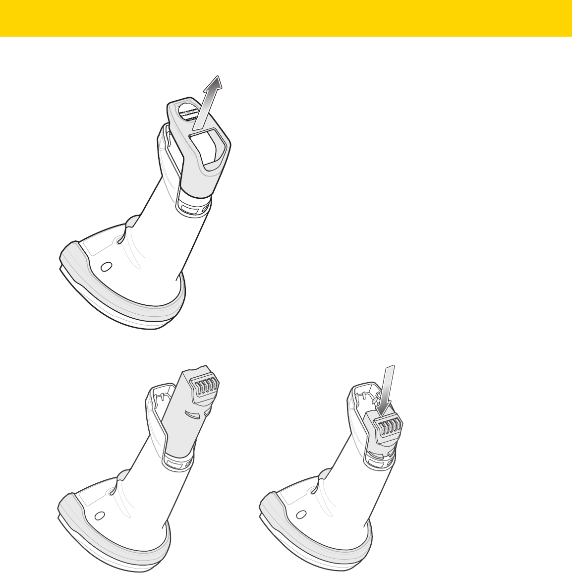
Getting Started 1 - 11
b. Lift the battery/PowerCap compartment cover off.
Figure 1-7 Removing the Battery/PowerCap Compartment Cover
c. Insert the battery/PowerCap into the battery/PowerCap compartment and push until it clicks into place.
Figure 1-8 Inserting the Battery/PowerCap
2. Replace the battery/PowerCap compartment cover.
a. Ensure the battery/PowerCap compartment knob is in the open position.
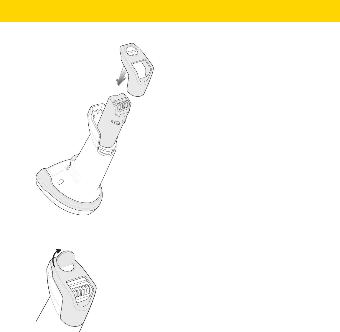
1 - 12 DS8178 Digital Scanner Product Reference Guide
b. Slide the battery/PowerCap compartment cover into place.
Figure 1-9 Replacing the Battery/PowerCap Compartment Cover
c. Use a coin to turn the battery/PowerCap compartment knob counterclockwise until it reaches the hard
stop.
Figure 1-10 Replacing the Battery/PowerCap Compartment Cover

Getting Started 1 - 13
Removing the Battery/PowerCap
Figure 1-11 Removing the Battery/PowerCap from the Scanner
To remove the battery/PowerCap from the scanner:
1. Remove the battery/PowerCap compartment cover.
a. Use a coin to turn the battery/PowerCap compartment knob counterclockwise until it reaches the hard stop
b. Lift the battery/PowerCap compartment cover off.
c. Lift the battery/PowerCap out of the battery/PowerCap compartment.
2. To replace the battery/PowerCap, see Inserting the Battery/PowerCap on page 1-10.
IMPORTANT When replacing the battery/PowerCap, wait at least 5 seconds after removing the old
battery/PowerCap before inserting the new battery/PowerCap. The PowerCap is fully charged
when shipped. The scanner must be inserted into the charge cradle to enable the PowerCap the
first time it is used.

1 - 14 DS8178 Digital Scanner Product Reference Guide
Inserting the Scanner in the Cradles
To insert the digital scanner in the CR8178-SC cradle:
1. Insert the scanner into the cradle top first ensuring that the cradle latch depression (see Figure 1-1 on page
1-2) connects with the scanner latch on the cradle.
2. Push the handle until it clicks into place, engaging the contacts in the cradle and digital scanner.
Figure 1-12 Inserting the Scanner in the CR8178-SC Cradle
To insert the digital scanner in the CR8178-PC cradle:
1. Insert the scanner straight down into the cradle top.
2. The digital scanner naturally rotates forward to engage the digital scanner contacts with the cradle contacts
Figure 1-13 Inserting the Scanner in the CR8178-PC Cradle
Scanner Latch

Getting Started 1 - 15
Sending Data to the Host Computer
The cradle receives data from the digital scanner via a wireless radio connection and transmits it to the host
computer via the host cable. The digital scanner and cradle must be paired for successful wireless communication.
Pairing
Pairing registers a scanner to the cradle such that the scanner and cradle can exchange information. The
CR8178-SC and CR8178-PC operate in two modes: Point-to-Point and Multipoint-to-Point. In Point-to-Point mode,
pair the digital scanner to the cradle either by inserting it in the cradle (if pair on contacts is enabled), or by
scanning the pairing bar code. In Multipoint-to-Point mode, you can pair up to seven scanners to one cradle. To use
this feature, scan the multipoint bar code in Multipoint-to-Point Communication on page 5-30 when the digital
scanner is connected to the cradle.
To pair the digital scanner with the cradle, insert the scanner in the cradle or scan the pairing bar code. (Pairing on
insertion into the cradle is enabled by default. See Pairing Methods on page 5-33.)
Lost Connection to Host
If scanned data does not transmit to the cradle's host, ensure that all cables are firmly inserted and the power
supply is connected to an appropriate AC outlet, if applicable. If scanned data still does not transmit to the host,
reestablish a connection with the host:
1. Disconnect the power supply from the cradle.
2. Disconnect the host interface cable from the cradle.
3. Wait three seconds.
4. Reconnect the host interface cable to the cradle.
5. Reconnect the power supply to the cradle, if the host requires.
6. Reestablish pairing with the cradle by inserting the scanner in the cradle or scan the pairing bar code. (Pairing
on insertion into the cradle is enabled by default. See Pairing Methods on page 5-33.)
Configuring the Scanner
Use the bar codes in this manual or the 123Scan
configuration program to configure the digital scanner. See
Chapter 6, User Preferences and each host chapter for information about programming the digital scanner using
bar code menus. See Chapter 2, 123Scan and Software Tools to configure the digital scanner using this
configuration program. 123Scan includes a help file.
Radio Communications
The digital scanner can communicate with remote devices via Bluetooth, or by pairing with a cradle. For radio
communication parameters, detailed information about operational modes, Bluetooth and pairing, see Chapter 5,
Radio Communications.
NOTE The pairing bar code that connects the digital scanner to a cradle is unique to each cradle.
Do not scan data or parameters until pairing completes.

1 - 16 DS8178 Digital Scanner Product Reference Guide
Accessories
The digital scanner ships with the battery or PowerCap (depending on configuration) and the DS8178 Quick Start
Guide. The following required accessories must be ordered separately:
•
Cradle, required for charging the battery/PowerCap (see Standard Cradle on page 1-3 and
Presentation Cradle on page 1-4).
•
Document Capture Stand for use with the CR8178-PC (p/n STND-DC0081W-04)
(see Using the Document Capture Stand on page 1-6).
•
Replacement battery for the DS8178 digital scanner.
•
Replacement PowerCap for the DS8178 digital scanner.
•
Interface cable for the appropriate interface.
•
Universal power supply, if the interface requires one.
See Accessories on page xxvi for the full list of power supplies and part numbers. Also see Scanner Configurations
on page xxv and Cradle Configurations on page xxvi for product configurations. For additional items, contact a
local Zebra representative or business partner.

CHAPTER 2 123SCAN AND
SOFTWARE TOOLS
Introduction
This chapter briefly describes the Zebra software tools available for customizing scanner operation.
123Scan
123Scan is a software tool that simplifies scanner setup and more.
Intuitive enough for first time users, the 123Scan wizard guides users through a streamlined setup process.
Settings are saved in a configuration file that can be printed as a single programming bar code for scanning,
emailed to a smart phone for scanning from its screen, or downloaded to the scanner using a USB cable.
Through 123Scan a user can:
•
Configure a scanner using a wizard.
•
Program the following scanner settings:
• Beeper tone / volume settings.
• Enable / disable symbologies.
• Communication settings.
•
Modify data before transmission to a host using:
• Advanced Data Formatting (ADF) - Scan one bar code per trigger pull.
• Multicode Data Formatting (MDF) - Scan many bar codes in one trigger pull (select scanners).
• Preferred Symbol - Single out one bar code on label of many (select scanners).
•
Load parameter settings to a scanner via the following.
•
Bar code scanning:
• Scan a paper bar code.
• Scan a bar code from a PC screen.
• Scan a bar code from a smart phone screen.
•
Download over a USB cable.
• Load settings to one scanner.
• Stage up to 10 scanners simultaneously (Powered USB Hub recommended with 0.5 amp / port).

2 - 2 DS8178 Digital Scanner Product Reference Guide
•
Validate scanner setup.
•
View scanned data within the utility's Data view screen.
•
Capture an image and save to a PC within the utility's Data view screen.
•
Review settings using the Parameter Report.
•
Clone settings from an already deployed scanner from the Start screen.
•
Upgrade scanner firmware.
•
Load settings to one scanner.
•
Stage up to 10 scanners simultaneously (Powered USB Hub recommended with 0.5 amp / port).
•
View statistics such as:
•
Asset tracking information
•
Time and usage information
•
Bar codes scanned by symbology
•
Battery/PowerCap diagnostics (select scanners).
•
Generate the following reports.
•
Bar Code Report - Programming bar code, included parameter settings, and supported scanner
models.
•
Parameter Report - Lists parameters programmed within a configuration file.
•
Inventory Report - Lists scanner asset tracking information.
•
Validation Report - Printout of scanned data from the Data view.
•
Statistics Report - Lists all statistics retrieved from the scanner.
For more information go to: zebra.com/123Scan
.
Communication with 123Scan
Use a USB cable to connect the scanner to a Windows host computer running 123Scan.
123Scan Requirements
•
Host computer running Windows 7, 8, and 10
•
Scanner
•
USB cable.
123Scan Information
For more information on123Scan, go to: zebra.com/123Scan.
For a 1 minute tour of 123Scan, go to: zebra.com/ScannerHowToVideos
.
To see a list of all of our software tools, go to: zebra.com/scannersoftware
.

123Scan and Software Tools 2 - 3
Scanner SDK, Other Software Tools, and Videos
Tackle all your scanner programming needs with our diversified set of software tools. Whether you need to simply
stage a device, or develop a fully featured application with image and data capture as well as asset management,
these tools help you every step of the way.
To download any of the following free tools, go to: zebra.com/scannersoftware
.
•
123Scan configuration utility
•
SDKs
•
Scanner SDK for Windows
•
Scanner SDK for Linux
•
Scanner SDK for Android
•
Scanner SDK for iOS
•
Drivers
•
OPOS driver
•
JPOS driver
•
USB CDC driver
•
TWAIN driver
•
Scanner Management Service (SMS) for Remote Management
•
Windows
•
Linux
•
Mobile Apps
•
Scanner Control App
• Android
• iOS
•
Scan-To-Connect Utility
• Android
• Windows
•
How-To-Videos
NOTE: For a list of SDK supported scanner functionality by communication protocol, see Appendix J,
Communication Protocol Functionality.

2 - 4 DS8178 Digital Scanner Product Reference Guide
Scanner Control App
The Scanner Control App (SCA) allows you to control a Bluetooth scanner from a phone or tablet without a cradle.
Use this app to showcase a Zebra Bluetooth scanner's capabilities and ease of control right from your phone.
The Scanner Control App supports Scan-To-Connect technology for one-step Bluetooth pairing, and allows you to
control the following scanner functions:
•
Program the beeper and LEDs.
•
Enable and disable symbologies.
•
Remotely trigger a scan.
The app displays scanned bar code data, and can query scanner asset information and battery health statistics.
The Scanner Control App also works with USB connected scanners like the MP7000, assuming your Android tablet
has a powered USB Host port.
The Scanner Control app is available on the Android Play, iOS App, and Zebra AppGallery stores. Source code is
available within the Zebra Scanner SDK for Android and iOS.
To watch a 1 minute tour of the Scanner Control App, go to: zebra.com/scannercontrolapp
.
Scan-To-Connect (STC) Utility
In one step, connect your Zebra Bluetooth scanner to a phone, tablet or PC by simply scanning a STC bar code.
Available as a standalone utility for Windows and Android operating system from zebra.com/scantoconnect
.
Source code is also available for easy app integration.
NOTE: The STC Utility allows you to pair a Bluetooth scanner to a phone, tablet or PC without using a cradle.

CHAPTER 3 DATA CAPTURE
Introduction
This chapter provides beeper and LED definitions, techniques involved in scanning bar codes, general instructions
and tips about scanning, and decode ranges.
Beeper and LED Indications
The digital scanner issues different beep sequences/patterns and an LED display to indicate status. Table 3-1
defines beep sequences/patterns and LED displays which occur during both normal scanning and while
programming the digital scanner.
In addition to the System/Decode LEDs, the DS8178 cordless digital scanner has a battery/PowerCap LED gauge
(see DS8178 Features on page 1-2).
The battery/PowerCap LED gauge is always active when inserted in the cradle. After the scanner is removed from
the cradle, it is active for four seconds.
After the trigger is held for three seconds the battery/PowerCap LED gauge remain active for four seconds after
trigger release.
Digital Scanner Indications
Table 3-1 Digital Scanner Beeper and LED Indications
Beeper Sequence LED Indication
Standard Use
Low/medium/high beeps Green Power up.
Scanning
None Green solid Presentation Mode on.
None No LED; green LED is
turned off
Presentation Mode off.

3 - 2 DS8178 Digital Scanner Product Reference Guide
Medium beep
(or as configured)
Green flash A bar code was successfully decoded. (See
User
Preferences Parameter Defaults on page 6-2
for
programming beeper sounds.)
Low/low/low/extra low
beeps
Red Parity error.
Four long low beeps Red A transmission error was detected in a scanned
symbol. The data is ignored. This occurs if a unit is
not properly configured. Check option setting.
Five long low beeps Red Conversion or format error.
None Red (fast blink) on
trigger pull
Scanner is disabled by a host command to the
scanner.
High None A <BEL> character is received over RS-232.
Wireless Operation
Low, high, low, high Red Out of batch storage memory, unable to store new bar
code.
Radio Indications
Low None Scanner inserted into a cradle (may be disabled).
Low, high Green Bluetooth connection established.
High, low Red Bluetooth disconnection event.
Long low, long high Red Bluetooth page timeout; remote device is out of
range/not powered.
Long low, long high, long
low, long high
None Bluetooth connection attempt was rejected by remote
device.
None Green (fast blink) Bluetooth attempting reconnection.
Five high None Bluetooth attempting reconnection (default is
disable).
Six high Blue (fast/fast/slow) Paging state indication.
Remaining Charge Indications
Four short high beeps Red (stays on) Low battery/PowerCap indication (on trigger release).
None Green
Amber
Red
Battery/PowerCap charge level: 51-100%
Battery/PowerCap charge level: 21-50%
Battery/PowerCap charge level: 0-20%
Battery/PowerCap charge level indication (state of
charge in % of present full charge capacity).
Table 3-1 Digital Scanner Beeper and LED Indications (Continued)
Beeper Sequence LED Indication

Data Capture 3 - 3
None Not lit when scanner sits
in the cradle
The cradle is either not providing current to the
scanner or the scanner is consuming more current
than the cradle is able to supply (see
Troubleshooting on page 4-8 for more information).
None Green/Red alternating
Amber/Red alternating
Red blinking
Battery end of life, battery charge level: 51-100%
Battery end of life, battery charge level: 21-50%
Battery end of life, battery charge level: 0-20%
When the battery indicator displays any one of these
patterns it is time to replace your battery.
Note: PowerCap does not support end-of-life
warning.
Parameter Programming
Long low/long high beeps Red Input error, incorrect bar code or Cancel scanned,
wrong entry, incorrect bar code programming
sequence; remain in program mode.
High/low beeps Green Keyboard parameter selected. Enter value using bar
code keypad.
High/low/high/low beeps Green Successful program exit with change in the parameter
setting.
ADF Programming
Low/high/low beeps None ADF transmit error.
High/low beeps Green Number expected. Enter another digit. Add leading
zeros to the front if necessary.
Low/low beeps Green Alpha expected. Enter another alphabetic character
or scan the End of Message bar code.
High/high beeps Green blinking ADF criteria or action is expected. Enter another
criteria or action or scan the Save Rule bar code.
High/low/low beeps Green All criteria or actions cleared for current rule, continue
entering rule.
High/low/high/low beeps Green
(turns off blinking)
Rule saved. Rule entry mode exited.
Long low/long high beeps Red Rule error. Entry error, wrong bar code scanned, or
criteria/action list is too long for a rule. Re-enter
criteria or action.
Low beep Green Deleted last saved rule. The current rule is left intact.
Low/high/high beeps Green All rules deleted.
Table 3-1 Digital Scanner Beeper and LED Indications (Continued)
Beeper Sequence LED Indication

3 - 4 DS8178 Digital Scanner Product Reference Guide
Cradle LED Indications
Long low/long high/long
low/long high beeps
Red Out of rule memory. Erase some existing rules, then
try to save rule again.
Long low/long high/long
low beeps
Green
(turns off blinking)
Cancel rule entry. Rule entry mode exited because of
an error or the user asked to exit rule entry.
Host Specific
USB only
Four high beeps None
Digital
scanner has not completed initialization. Wait
several seconds and scan again.
RS-232 only
High/high/high/low beeps Red RS-232 receive error.
High beep None A <BEL> character is received when Beep on <BEL>
is enabled (Point-to-Point mode only).
Virtual Tether Alarm
High/low continuous beeps Fast blinking alternating
green and red
The scanner disconnects over Bluetooth from the
cradle (Virtual Tether Alarm enabled).
Note: Virtual Tether Alarm when enabled activates on
the scanner and cradle.
Table 3-1 Digital Scanner Beeper and LED Indications (Continued)
Beeper Sequence LED Indication
Table 3-2 Cradle LED Indications
LED Indication
Standard Use
Green (stays on) Power Up
Radio Indications
Green (off, then on) Bluetooth connection established
Blue Page button
Blue (fast/fast/slow) Page issued
Charging Indications
Amber (stays on) Pre-charging
Amber blinking and the charge
gauge LED on scanner is on.
Charging

Data Capture 3 - 5
Table 3-3 lists the conditions in which the specified host controls the System Indicator LED.
Amber blinking and the charge
gauge LED on scanner is off.
The cradle is either not providing current to the scanner or
the scanner is consuming more current than the cradle can
supply (see Troubleshooting on page 4-8 for more
information).
Green (stays on) Fully charged
Amber fast blinking Charging error
Red blinking and the charge
gauge LED on scanner is on.
Charging, but the battery is near end of its life and should
be replaced.
Red blinking and the charge
gauge LED on scanner is off
The cradle is either not providing current to the scanner or
scanner is consuming more current than cradle can supply;
the battery is near end of its life and should be replaced
(see Troubleshooting on page 4-8 for more information).
Red (stays on) Fully charged, but the battery is near end of its life and
should be replaced.
Red fast blinking Charging error; the battery is near end of its life and should
be replaced.
Virtual Tether Alarm
Fast blinking alternating green
and red
The scanner disconnects over Bluetooth from the cradle
(Virtual Tether Alarm enabled).
Maintenance Indications
Red (stays on) Enter boot loader
Red blinking Firmware installation
Table 3-3 Host Controlled Cradle LED Indications
LED Indication
123Scan
Slow Blinking Green Scanner connected to 123Scan.
Fast Blinking Red File being transferred to the scanner (parameters and
firmware).
Slow Blinking Red Firmware activated on the scanner, loaded into memory.
Solid Green Programming completed successfully (parameters and
firmware).
Solid Red Error State.
Table 3-2 Cradle LED Indications (Continued)
LED Indication

3 - 6 DS8178 Digital Scanner Product Reference Guide
SMS
Blinking Red
(Both scanner and cradle)
Loading the SMS package to scanner.
Table 3-3 Host Controlled Cradle LED Indications (Continued)
LED Indication

Data Capture 3 - 7
Scanning
Hand-Held Scanning
1. Aim the digital scanner at a bar code and pull the trigger to decode.
2. Press the trigger until the digital scanner beeps, indicating the bar code is successfully decoded. For more
information on beeper and LED definitions, see Beeper and LED Indications on page 3-1.
Figure 3-1 Scanning in Hand-Held Mode
Hands-Free Scanning
The scanner is in hands-free (presentation) mode when it sits in the CR8178-PC cradle. During idle conditions the
scanner operates in object detection mode, where it automatically wakes up to decode a bar code presented in the
field of view. In object detection mode it is normal for the illumination LEDs to be dimly lit.
To scan:
1. Ensure all connections are secure (see appropriate host chapter).
2. Present the bar code in the scanner field of view.
NOTE The standard digital scanner emits a red illumination with a red aim dot (pictured in Figure 3-1 and Figure
3-2). The Healthcare configuration emits a white illumination with a green aim dot.

3 - 8 DS8178 Digital Scanner Product Reference Guide
3. Upon successful decode, the scanner beeps and the LED flashes green. (For more information about beeper
and LED definitions, Beeper and LED Indications on page 3-1).
Figure 3-2 Scanning in Hands-Free Mode
Aiming with Digital Scanner
When scanning, the digital scanner projects a red LED dot which allows positioning the bar code within its field of
view. See Decode Ranges on page 3-10 for the proper distance to achieve between the digital scanner and a bar
code.
Figure 3-3 Aiming Dot
If necessary, the digital scanner turns on its red illumination LEDs to illuminate the target bar code.
To scan a bar code, center the symbol.
Figure 3-4 Scanning Orientation with Aiming Dot
1D bar code
2D bar code

Data Capture 3 - 9
The digital scanner can also read a bar code presented within the aiming dot not centered. The top examples in
Figure 3-5 show acceptable aiming options, while the bottom examples can not be decoded.
Figure 3-5 Acceptable and Incorrect Aiming
The aiming dot is smaller when the digital scanner is closer to the symbol and larger when it is farther from the
symbol. Scan symbols with smaller bars or elements (mil size) closer to the digital scanner, and those with larger
bars or elements (mil size) farther from the digital scanner.
The digital scanner beeps to indicate that it successfully decoded the bar code. For more information on beeper
and LED definitions, see Table 3-1.

3 - 10 DS8178 Digital Scanner Product Reference Guide
Decode Ranges
Table 3-4 DS8178 Decode Ranges
Bar Code
Type
Symbol Density
DS8178-SR
Typical Working Ranges
DS8178-HC
Typical Working Ranges
Near Far Near Far
Code 39 3.0 mil
2.2 in/5.6 cm 5.0 in/12.7 cm 1.4 in/3.6 cm 5.1 in/13.0 cm
20.0 mil
0.0 in/0.0 cm 36.8 in/93.5 cm 0.0 in/0.0 cm 22.4 in/56.9 cm
Code 128 3.0 mil
2.6 in/6.6 cm 4.5 in/11.4 cm 1.8 in/4.6 cm 4.1 in/10.4 cm
5.0 mil
1.6 in/4.1 cm 8.4 in/21.3 cm 1.2 in/3.0 cm 8.1 in/20.6 cm
15 mil
0.0 in/0.0 cm 27.1 in/68.8 cm 1.0 in/ 2.5 cm 16.9 in/42.9 cm
100% UPC 13.0 mil
0.0 in/0.0 cm 24.0 in/61.0 cm 0.0 in/0.0 cm 15.9 in/40.4 cm
PDF417 5 mil
2.3 in/5.8 cm 6.4 in/16.3 cm 1.5 in/3.8 cm 6.1 in/15.5 cm
6.67 mil
1.8 in/4.6 cm 8.5 in/21.6 cm 1.1 in/2.8 cm 8.1 in/20.6 cm
Data Matrix 5.0 mil
n/a n/a 1.9 in/4.8 cm 4.5 in/11.4 cm
7.5 mil
2.1 in/5.3 cm 6.9 in/ 17.5 cm 1.3 in/ 3.3 cm 6.7 in/17.0 cm
10.0 mil
1.1 in/2.8 cm 9.9 in/ 25.1 cm 0.6 in/1.5 cm 8.5 in/ 21.6 cm
QR Code 10.0 mil
1.0 in/2.5 cm 8.6 in/ 21.8 cm 0.6 in/1.5 cm 7.7 in/19.6 cm
20.0 mil
0.1 in/0.3 cm 17.6 in/ 44.7 cm 0.0 in/0.0 cm 12.5 in/ 31.8 cm

CHAPTER 4 MAINTENANCE,
TROUBLESHOOTING,
AND TECHNICAL
SPECIFICATIONS
Introduction
This chapter provides suggested digital scanner maintenance, troubleshooting, technical specifications, and signal
descriptions (pin-outs).
Maintenance
IMPORTANT Use pre-moistened wipes and do not allow liquid cleaner to pool.
1
Ensure the following items are addressed when using sodium hypochlorite (bleach) based
cleaners:
• For scanner only. Do not use on cradle.
• Always follow the manufacturer’s recommended instructions: use gloves during application and
remove the residue afterwards with a damp cloth to avoid prolonged skin contact while
handling the scanner.
• Due to the powerful oxidizing nature of sodium hypochlorite, the metal surfaces, including
electrical contacts on the scanner, are prone to oxidation (corrosion) when exposed to this
chemical in the liquid form (including wipes) and should be avoided. In the event that these
type of disinfectants come in contact with metal on the scanner, prompt removal with a
dampened cloth after the cleaning step is critical.
IMPORTANT To avoid damage to the device, use only approved cleaning and disinfecting agents listed below.
The use of non-approved cleaning or disinfecting agents may void the warranty.

4 - 2 DS8178 Digital Scanner Product Reference Guide
Known Harmful Ingredients
The following chemicals are known to damage the plastics on Zebra scanners and should not come in contact with
the device:
• Acetone
• Ammonia solutions
• Aqueous or alcoholic alkaline solutions
• Aromatic and chlorinated hydrocarbons
• Benzene
• Carbolic acid
• Compounds of amines or ammonia
• Ethanolamine
• Ethers
• Ketones
• TB-lysoform
• Toluene
• Trichloroethylene.
Approved Cleaners for Standard DS8178 Digital Scanners and CR8178 Cradles
•
Isopropyl alcohol 70% (including wipes)
•
10% Bleach (Sodium Hypochlorite 0.55%) and 90% Water solution
1 (see important note on page 4-1)
•
3% Hydrogen Peroxide and 97% Water solution
•
Mild dish soap.
Approved Disinfectant Cleaners for Healthcare Configurations of the DS8178 Digital
Scanners and CR8178 Cradles
Only use cleaning agents from the following list, following the manufacturer’s instructions:
•
10% Bleach (Sodium Hypochlorite 0.55%) and 90% Water solution
1 (see important note on page 4-1)
•
3% Hydrogen Peroxide and 97% Water solution
•
91% Isopropyl Alcohol and 9% Water solution
•
Azowipe
•
Brulin BruTab 6S Tablets
1 (see important note on page 4-1)
•
Clinell Universal Sanitizing Wipes
•
Clinell Universal Wipes
•
Clorox Dispatch Hospital Cleaner Disinfectant Towels with Bleach
1 (see important note on page 4-1)
•
Clorox Formula 409 Glass and Surface Cleaner
•
Clorox Healthcare Bleach Germicidal Wipes
1 (see important note on page 4-1)
•
Clorox Healthcare Hydrogen Peroxide Wipes
•
Clorox Healthcare Multi-Surface Quat Alcohol Wipes
•
Diversey D10 Concentrate Detergent Sanitizer
•
Diversey Dimension 256 Neutral Disinfectant Cleaner

Maintenance, Troubleshooting, and Technical Specifications 4 - 3
•
Diversey Oxivir Tb Wipes
•
Diversey Virex II 256 One-Step Disinfectant Cleaner
•
Medipal Alcohol Wipes
•
Metrex CaviCide
•
Metrex CaviCide 1
•
Metrex CaviWipes
•
Metrex CaviWipes 1
•
PDI Easy Screen® Cleaning Wipe
•
PDI Sani-Cloth AF3 Germicidal Disposable Wipe
•
PDI Sani-Cloth Bleach Germicidal Disposable Wipe
1 (see important note on page 4-1)
•
PDI Sani-Cloth HB Sani-Germicidal Disposable Wipe
•
PDI Sani-Cloth Plus Germicidal Disposable Cloth
•
PDI Super Sani-Cloth Germicidal Wipe
•
Progressive Products Wipes Plus
•
Sani Professional Disinfecting Multi-Surface Wipes
•
Sani-Hands® Instant Hand Sanitizing Wipes
•
SC Johnson Windex Original Glass Cleaner with Ammonia-D
•
Spartan Hepacide Quat II
•
Sterets Alcowipe
•
Steris Coverage Plus Germicidal
•
Veridien Viraguard
•
WipesPlus Hospital/Surgical Wipes.
Cleaning the Digital Scanner
Routinely cleaning the exit window is required. A dirty window may affect scanning accuracy. Do not allow any
abrasive material to touch the window.
To clean the scanner:
1. Dampen a soft cloth with one of the approved cleaning agents listed above or use pre-moistened wipes.
2. Gently wipe all surfaces, including the front, back, sides, top and bottom. Never apply liquid directly to the
scanner. Be careful not to let liquid pool around the scanner window, trigger, cable connector or any other area
on the device.
3. Be sure to clean the trigger and in between the trigger and the housing (use a cotton-tipped applicator to reach
tight or inaccessible areas).
4. Do not spray water or other cleaning liquids directly into the exit window.
5. Wipe the scanner exit window with a lens tissue or other material suitable for cleaning optical material such as
eyeglasses.

4 - 4 DS8178 Digital Scanner Product Reference Guide
6. Immediately dry the scanner window after cleaning with a soft non-abrasive cloth to prevent streaking.
7. Allow the unit to air dry before use.
8. Scanner connectors:
a. Dip the cotton portion of a cotton-tipped applicator in isopropyl alcohol.
b. Rub the cotton portion of the cotton-tipped applicator back-and-forth across the connector on the Zebra
scanner at least 3 times. Do not leave any cotton residue on the connector.
c. Use the cotton-tipped applicator dipped in alcohol to remove any grease and dirt near the connector area.
d. Use a dry cotton tipped applicator and rub the cotton portion of the cotton-tipped applicator back-and-forth
across the connectors at least 3 times. Do not leave any cotton residue on the connectors.

Maintenance, Troubleshooting, and Technical Specifications 4 - 5
Troubleshooting
Table 4-1 Troubleshooting
Problem Possible Causes Possible Solutions
The aiming dot does not
appear when pressing the
trigger.
No power to the digital scanner. If the configuration requires a power supply,
re-connect the power supply.
Incorrect host interface cable is used. Connect the correct host interface cable.
Interface/power cables are loose. Re-connect cables.
Digital scanner is disabled. For IBM 468x and USB IBM hand-held, IBM
table-top, and OPOS modes, enable the digital
scanner via the host interface. Otherwise, see the
technical person in charge of scanning.
If using RS-232 Nixdorf B mode, CTS
is not asserted.
Assert CTS line.
Aiming pattern is disabled. Enable the aiming pattern. See
Hand-Held Decode
Aiming Pattern on page 6-27
.
Digital scanner
emits aiming
dot, but does not decode the
bar code.
Digital scanner
is not programmed for
the correct bar code type.
Program the digital scanner to read that type of bar
code. See
Chapter 13, Symbologies
.
Bar code symbol is unreadable. Scan test symbols of the same bar code type to
determine if the bar code is defaced.
The aiming dot is not correctly placed
on the symbol.
Move the symbol so that the aiming dot is within the
field of view (see
Aiming with Digital Scanner on
page 3-8
).
Distance between digital scanner and
bar code is incorrect.
Move the scanner closer to or further from the bar
code. See
Decode Ranges on page 3-10
.

4 - 6 DS8178 Digital Scanner Product Reference Guide
Digital scanner
decodes bar
code, but does not transmit the
data to the host.
Digital scanner
is not programmed for
the correct host type.
Scan the appropriate host type programming bar
code. See the chapter corresponding to the host
type.
Interface cable is loose. Re-connect the cable.
Cradle is not programmed for the
correct host type.
Check digital scanner host parameters or edit
options.
Digital scanner
is not paired to host
connected interface.
Pair digital scanner to the cradle by scanning the
PAIR bar code on the cradle.
Cradle has lost connection to the host. In this exact order: disconnect power supply;
disconnect host cable; wait three seconds;
reconnect host cable; reconnect power supply;
reestablish pairing.
If the digital scanner emits four long
low beeps, a transmission error
occurred.
This occurs if a unit is not properly
configured or connected to the wrong
host type.
Set the scanner's communication parameters to
match the host's setting.
If the digital scanner emits 5 low beeps,
a conversion or format error occurred.
Configure the digital scanner's conversion
parameters properly.
If the digital scanner emits low/high/low
beeps, it detected an invalid ADF rule.
Program the correct ADF rules. Refer to the
Advanced Data Formatting Programmer Guide.
Host displays scanned data
incorrectly.
Digital scanner
is not programmed to
work with the host.
Scan the appropriate host type programming bar
code.
For RS-232, set the digital scanner's
communication parameters to match the host's
settings.
For a Keyboard Wedge configuration, program the
system for the correct keyboard type, and turn off
the CAPS LOCK key.
Program the proper editing options (e.g., UPC-E to
UPC-A Conversion).
Digital scanner
emits short
low/short medium/short high
beep sequence (power-up
beep sequence) more than
once.
The USB bus may put the digital
scanner in a state where power to the
scanner is cycled on and off more than
once.
Normal during host reset.
Digital scanner
emits 4 short
high beeps during decode
attempt.
Digital scanner
has not completed
USB initialization.
Wait several seconds and scan again.
Digital scanner
emits
Low/low/low/extra low beeps
when not in use.
RS-232 receive error. Normal during host reset. Otherwise, set the digital
scanner's RS-232 parity to match the host setting.
Table 4-1 Troubleshooting (Continued)
Problem Possible Causes Possible Solutions

Maintenance, Troubleshooting, and Technical Specifications 4 - 7
Digital scanner
emits low/high
beeps during programming.
Input error, incorrect bar code or
Cancel bar code was scanned.
Scan the correct numeric bar codes within range for
the parameter programmed.
Digital scanner
emits
low/high/low/high beeps during
programming.
Out of host parameter storage space. Scan
Default Parameters on page 6-5
.
Out of memory for ADF rules. Reduce the number of ADF rules or the number of
steps in the ADF rules.
During programming, indicates out of
ADF parameter storage space.
Erase all rules and re-program with shorter rules.
Digital scanner
emits
low/high/low beeps.
ADF transmit error. Refer to the Advanced Data Formatting Guide for
information.
Invalid ADF rule is detected. Refer to the Advanced Data Formatting Guide for
information.
Digital scanner
emits a
power-up beep after changing
USB host type.
The USB bus re-established power to
the digital scanner.
Normal when changing USB host type.
Digital scanner
emits one high
beep when not in use.
In RS-232 mode, a <BEL> character
was received and Beep on <BEL>
option is enabled.
Normal when Beep on <BEL> is enabled and the
digital scanner is in RS-232 mode.
Digital scanner
emits frequent
beeps.
No power to the scanner. Check the system power. If the configuration
requires a power supply, re-connect the power
supply.
Incorrect host interface cable is used. Verify that the correct host interface cable is used. If
not, connect the correct host interface cable.
Interface/power cables are loose. Check for loose cable connections and re-connect
cables.
Digital scanner
emits five long
low beeps after a bar code is
decoded.
Conversion or format error was
detected.
The scanner conversion parameters
are not properly configured.
Ensure the scanner conversion parameters are
properly configured.
Conversion or format error was
detected.
An ADF rule was set up with characters
that can't be sent for the host selected.
Change the ADF rule, or change to a host that can
support the ADF rule.
Conversion or format error was
detected.
A bar code was scanned with
characters that can't be sent for that
host.
Change the bar code, or change to a host that can
support the bar code.
Digital scanner LED blinks
even if the pairing request was
canceled from remote
iOS/Android
™
device.
If pass key entry is canceled from the
tablet/phone, the digital scanner
remains in the pass key entry mode for
30 seconds before timing out.
To exit pass key entry mode scan
Cancel on page
H-1
or scan any other bar code.
Remaining Charge LED is red. Battery or PowerCap charge is low Insert the scanner in cradle.
Table 4-1 Troubleshooting (Continued)
Problem Possible Causes Possible Solutions

4 - 8 DS8178 Digital Scanner Product Reference Guide
Dump Scanner Parameters
To debug a scanner issue, scan the following bar code with the scanner connected in USB HID keyboard mode to
Microsoft
®
Windows Notepad or Wordpad, or via RS-232 to Windows Hyperterminal. This outputs all the scanner's
asset tracking information and parameter settings to a text document.
See the parameter numbers in Appendix A, Standard Parameter Defaults to interpret the parameter/attribute
numbers in the output.
Four short high beeps and
Remaining Charge LED is red.
Battery or PowerCap charge is very
low.
Insert the scanner in cradle.
Cradle LED blinks amber
rapidly and the Remaining
Charge LED is not lit.
Cradle is not providing current to the
scanner.
Make sure scanner is securely seated in its cradle.
If this does not resume the battery or PowerCap
charging, clean and dry the electrical contacts on
the scanner and cradle (See cleaning instructions of
Scanner connector, step 8 on page 4-4 for more
information).Then, replace the scanner in the cradle
and make sure it sits properly in the base.
Remaining Charge LED on
scanner alternates between
red and green or between red
and amber and the Cradle LED
blinks red.
Battery is near the end of its life. Replace the battery.
Cradle LED blinks red and the
Remaining Charge
LED on
scanner is not lit.
Cradle is either not providing current to
the scanner or the scanner is
consuming more current than the
cradle is able to supply, and battery is
near the end of its life.
Clean and dry the electrical contacts on the scanner
and cradle (See cleaning instructions of Scanner
connector, step 8 on page 4-4 for more
information).Then, replace the scanner in the cradle
and make sure it sits properly in the base.
Replace the battery.
Cradle LED is red. Battery is charged but is near end of its
life.
Replace the battery.
Cradle LED blinks red
rapidly.
Charging error and battery is near end
of its life.
Clean and dry the electrical contacts on the scanner
and cradle (See cleaning instructions of Scanner
connector, step 8 on page 4-4 for more
information).Then, replace the scanner in the
cradle, making sure it seats properly in the base.
Replace the battery.
Table 4-1 Troubleshooting (Continued)
Problem Possible Causes Possible Solutions
NOTE If after performing these checks the digital scanner still experiences problems, contact the distributor or
call support.
NOTE Use 123Scan if available as an alternative to using this feature. 123Scan is the preferable method for
outputting scanner information.
NOTE For proper formatting, it may be necessary to first scan <DATA> <SUFFIX 1> (1) on page 6-45.
Maintenance, Troubleshooting, and Technical Specifications 4 - 9
Send Versions
Report Software Version
Scan the following bar code to send the version of software installed in the scanner.
Serial Number
Scan the following bar code to send the scanner serial number to the host.
Manufacturing Information
Scan the following bar code to send the scanner manufacturing information to the host.
Dump Scanner Parameters
Report Software Version
Serial Number
Manufacturing Information

4 - 10 DS8178 Digital Scanner Product Reference Guide
Technical Specifications
NOTE Operating current specifications are subject to change.
Table 4-2 Technical Specifications
Item Description
Physical Characteristics
Dimensions
Scanner
Presentation Cradle
Desk/Wall Cradle
6.6 in H x 2.6 in W x 4.2 in D / 16.8 cm H x 6.7 cm W x 10.6 cm D
2.9 in H x 3.7 in W x 4.8 in D / 7.3 cm H x 9.4 cm W x 12.3 cm D
2.8 in H x 3.3 in W x 8.3 in D / 7.2 cm H x 8.4 cm W x 21.1 cm D
Weight - DS8178-SR/DL
Scanner (with battery)
Scanner (with PowerCap)
Presentation Cradle
Desk/Wall Cradle
8.2 oz / 232 g
7.6 oz / 215 g
5.4 oz / 153 g
6.5 oz / 183 g
Weight - DS8178-HC
Scanner
Presentation Cradle
Desk/Wall Cradle
8.3 oz / 237 g
6.5 oz / 183 g
7.1 oz / 202 g
Cradle Operating Currents
CR8178-SC Operating Current (mA)
T
A
=25C
Mode Typ Max
Idle @ VIN = 12V 43 50
Idle @ VIN = 5V 93 100
Charging, Standard USB 470 500
Charging, BC1.2 CDP 1350 1500
Charging, BC1.2 DCP 1100 1200
Charging, 5V non-USB 730 750
Charging, 12V non-USB 743 1000
CR8178-PC Operating Current (mA)
T
A
=25C
Mode Typ Max
Idle @ VIN = 12V 37 45
Idle @ VIN = 5V 77 85
Charging, Standard USB 470 500
Charging, BC1.2 CDP 1350 1500
Charging, BC1.2 DCP 1100 1200
Charging, 5V non-USB 730 750
Charging, 12V non-USB 743 1000
Available Colors Twilight Black, Nova White, Healthcare White (DS8178-HC)
Supported Host Interfaces USB, RS-232, Keyboard Wedge, RS-485 (IBM 46xx)
USB Certification DS8178 is USB2.0 Full Speed Compliant, visit
USB.org
for more details.
Keyboard Support Supports 97 international keyboards
FIPS Security Certification Certified Compliant with FIPS 140-3

Maintenance, Troubleshooting, and Technical Specifications 4 - 11
User Indicators
Scanner Multi-function LED (Decode, error, paging status);
Beeper (Decode, paging);
Power Gauge
Direct Decode Indicator
Cradle Multi-function LED (Power, error, charge status)
Performance Characteristics
Light Source
DS8178-SR/DL
DS8178-HC
Aiming Pattern: Circular 617nm amber LED
Aiming Pattern: Circular 528nm true green LED
Illumination
DS8178-SR/DL
DS8178-HC
Two 645nm red LEDs
Two warm white LEDs
Imager Field of View 48.0° horizontal, 37.0° vertical
Image Sensor 1,280 x 960 pixels
Minimum Print Contrast 16% minimum reflective difference
Skew Tolerance +/- 60°
Pitch Tolerance +/- 60°
Roll Tolerance 360°
Image Capture
Graphics Format Support Images can be exported as Bitmap, JPEG, or TIFF
Resolution (A4 document) 109 PPI
User Environment
DS8178-SR/DL Temperatures Operating Temperature: 32° to 122°F / 0° to 50°C
Presentation Mode Operation: 32° to 104°F / 0° to 40°C
Charging Temperature: 32° to 104°F / 0° to 40°C
DS8178-HC Temperatures Operating Temperature (Scanner): 32° to 122°F / 0° to 50°C
Presentation Mode Operation: 32° to 104°F / 0° to 40°C
Charging Temperature: 32° to 104°F / 0° to 40°C
Storage Temperature -40° to 158°F / -40° to 70°C
Humidity 5% to 95% RH, non-condensing
Drop Specification (Scanner) Designed to withstand multiple drops at 6.0 ft./1.8 m to concrete
Tumble Specification (Scanner) Designed to withstand 2,000 tumbles in 1.5 ft./0.5 m tumbler
Note: 1 tumble = 0.5 cycle
Ambient Light Immunity 0 to 9000 Foot Candles/0 to 96,840 Lux
Environmental Sealing Scanner rated IP52
Electrostatic Discharge (ESD) - Scanner,
Presentation Cradle, Desk/Wall Cradle
+/-15kV Air, +/-8kV Indirect, +/-8kV Direct
Table 4-2 Technical Specifications (Continued)
Item Description

4 - 12 DS8178 Digital Scanner Product Reference Guide
Wireless Connectivity
Bluetooth Radio Standard Bluetooth Version 4.0 with BLE: Class 1 330 ft. (100m) and
Class 2 33 ft. (10m), Serial Port and HID Profiles
Adjustable Bluetooth Power Class 1: Output power adjustable down from 4 dBm in 8 Steps
Class 2: Output power adjustable down from 2 dBm in 8 Steps
Power
PowerPrecision+ Li-Ion Battery Capacity: 2500 mAh
Number of scans from full charge: 65,000 (at one scan per second)
Typical Charge Time From Empty To Full
CR8178-SC CR8178-PC
Standard USB 7 hrs 45 min 9 hrs 15 min
BC1.2 USB 3 hrs 3 hrs 15 min
External 5V Source 4 hrs 30 min 5 hrs
External 12V Source 2 hrs 15 min 2 hrs 15 min
PowerCap Capacitor Capacity: 440 Farads
Number of Scans from Full Charge: 2,000 (at one scan per second)
Number of Scans from Ready-To-Scan at 20% of Full Charge (default):
200 (at one scan per second)
Number of Scans from Ready-To-Scan at 15% of Full Charge: 100 (at one
scan per second)
Charge Time From Empty to Full: 30 min over USB
Charge Time From Audible Low Charge Warning to Ready-to-Scan at
20% of Full Charge (default): 90 sec over USB (see Medium Threshold
under
Battery/PowerCap Threshold on page 6-41
)
Charge Time From Audible Low Charge Warning to Ready-to-Scan at
15% of Full Charge: 35 sec over USB
Accessories See
Table C
.
Symbol Decode Capability
1D UPC/EAN, UPC/EAN with supplements, Bookland EAN, ISSN, UCC
Coupon Extended, Code 39, Code 39 Full ASCII, Code 128, ISBT Code
128, Code 93, Codabar/NW7, Code 11, MSI Plessey, UPC/EAN, I 2 of 5,
Korean 3 of 5, GS1 DataBar, Base 32 (Italian Pharma), ISBT Concat
2D PDF417, MicroPDF417, Composite Codes, TLC-39, Aztec, DataMatrix,
MaxiCode, QR Code, Micro QR, Chinese Sensible (Han Xin), China GM
Code, DotCode, Dotted DataMatrix
Postal Australian Post, US PLANET, Royal Mail 4 State, US POSTNET, KIX
(Dutch), UK Postal, Japan Post, UPU 4 State FICS (Post US4), USPS 4
State (Post US3), Canadian Post (Postbar)
Digimarc Digital watermark technology
Table 4-2 Technical Specifications (Continued)
Item Description

Maintenance, Troubleshooting, and Technical Specifications 4 - 13
Minimum Element Resolution
Code 39 3.0 mil
Code 128 3.0 mil
DataMatrix 5.0 mil
QR 5.0 mil
Utilities and Management
123Scan Programs scanner parameters, upgrades firmware, provides scanned bar
code data and prints reports. See
Chapter 2, 123Scan and Software
Tools
.
Symbol Scanner SDK Generates a fully-featured scanner application, including documentation,
drivers, test utilities and sample source code.
zebra.com/ScannerSDKforWindows
Scanner Management Service (SMS) Remotely manages your Zebra scanner and queries its asset information.
zebra.com/sms
Decode Ranges (Typical)* See
Decode Ranges on page 3-10
.
Table 4-2 Technical Specifications (Continued)
Item Description
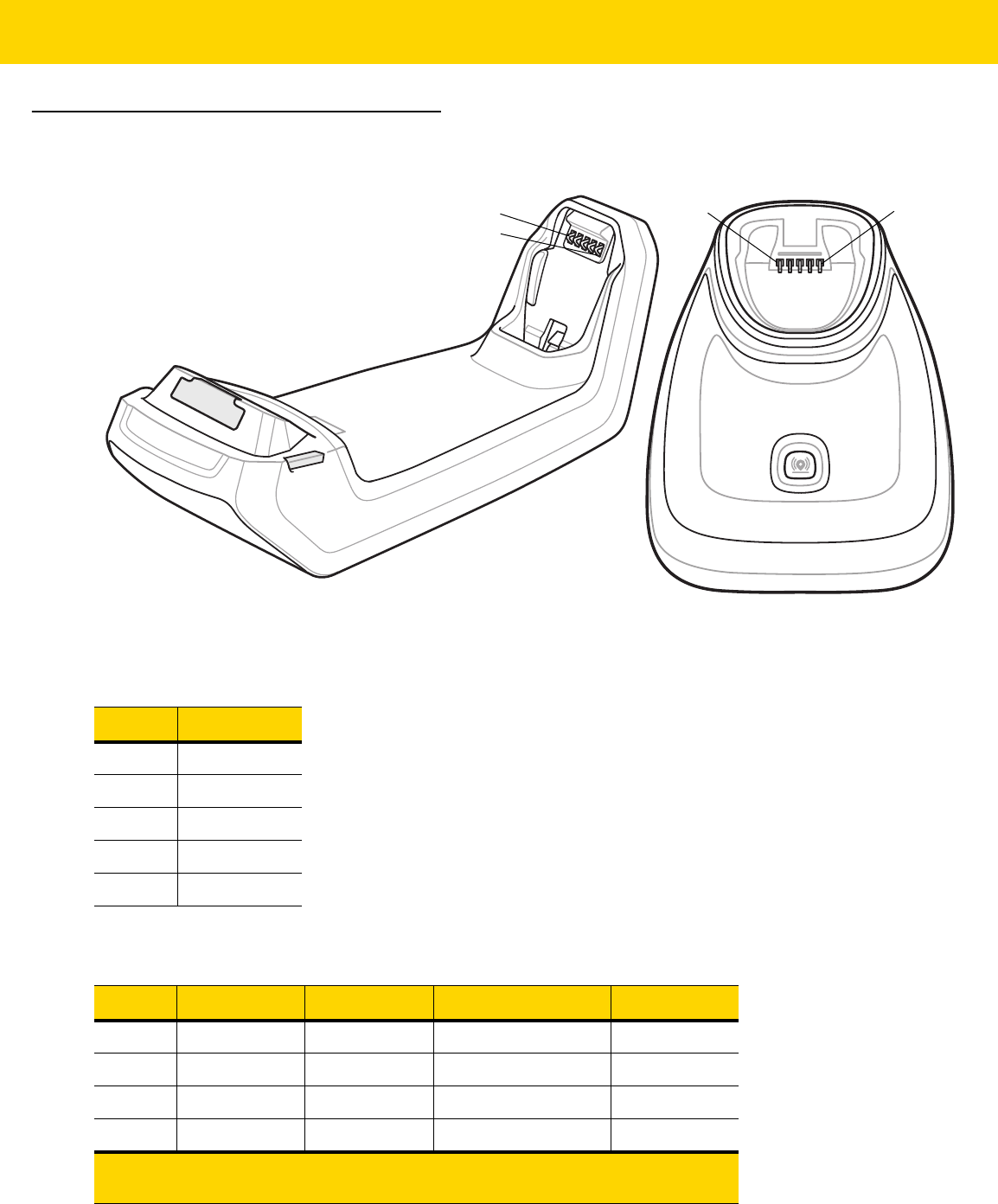
4 - 14 DS8178 Digital Scanner Product Reference Guide
Cradle Signal Descriptions
Figure 4-1 Cradle Pin-outs
The signal descriptions in Table 4-3 apply to the contacts on the digital scanner and are for reference only.
Table 4-3 Signal Pin-outs
Pin Function
1 PACK+
2 THERM
3 COM1
4 COM2
5 GND
Table 4-4 10 Pin Host Interface Connectors
Pin USB RS-232 Keyboard Wedge RS-485*
1 CABLE_ID CABLE_ID CABLE_ID
2 5VDC 5VDC 5VDC 5VDC
3 GND GND GND GND
4 TXD KBD_CLK IBM_TXD
*Additional RS-485 transceiver hardware located within the
cable.
PIN 5
PIN 1
PIN 5
PIN 1

Maintenance, Troubleshooting, and Technical Specifications 4 - 15
5 D+ RXD TERM_DATA IBM_RXD
6 Short to Pin 1 RTS KBD_DATA IBM_DIR
7 D- CTS TERM_CLK
8 1Meg resistor to pin 1 2Meg resistor to
pin 1
9
10 12VDC
(optional)
12VDC
(optional)
12VDC (optional) 12VDC
(optional)
SHELL Shield Shield Shield Shield
Table 4-4 10 Pin Host Interface Connectors (Continued)
Pin USB RS-232 Keyboard Wedge RS-485*
*Additional RS-485 transceiver hardware located within the
cable.

4 - 16 DS8178 Digital Scanner Product Reference Guide

CHAPTER 5 RADIO
COMMUNICATIONS
Introduction
This chapter provides information about the modes of operation and features available for wireless communication
between the DS8178 cordless digital scanners, cradles and hosts. The chapter also includes the parameters
necessary to configure the digital scanner.
The digital scanner ships with the settings shown in the Radio Communication Default Table on page 5-2 (also see
Appendix A, Standard Parameter Defaults for all defaults). If the default values suit requirements, programming is
not necessary.
Setting Parameters
To set feature values, scan a single bar code or a short bar code sequence. The settings are stored in non-volatile
memory and are preserved even when the scanner powers down.
If not using the default host, select the host type (see each host chapter for specific host information) after the
power-up beeps sound. This is only necessary upon the first power-up when connected to a new host.
To return all features to default values, scan a bar code in Default Parameters on page 6-5. Throughout the
programming bar code menus, asterisks (
*) indicate default values.
NOTE Most computer monitors allow scanning bar codes directly on the screen. When scanning from the screen,
be sure to set the document magnification to a level where you can see the bar code clearly, and bars
and/or spaces do not merge.
*Enable Parameter
(1)
Feature/option
* Indicates default
Option value

5 - 2 DS8178 Digital Scanner Product Reference Guide
Scanning Sequence Examples
In most cases, scanning one bar code sets the parameter value. For example, to enable Wi-Fi Friendly Mode, scan
the Enable Wi-Fi Friendly Mode bar code listed under Wi-Fi Friendly Mode on page 5-12. The scanner issues a
fast warble beep and the LED turns green, signifying a successful parameter entry.
Other parameters, such as Bluetooth Friendly Name, require scanning several bar codes. See the parameter
descriptions for this procedure.
Errors While Scanning
Unless otherwise specified, to correct an error during a scanning sequence, just re-scan the correct parameter.
Radio Communications Parameter Defaults
Table 5-1 lists the defaults for radio communication parameters. Change these values in one of two ways:
•
Scan the appropriate bar codes in this chapter. The new value replaces the standard default value in
memory. To recall default parameter values, see Default Parameters on page 6-5.
•
Configure the scanner using the 123Scan
configuration program. See Chapter 2, 123Scan and Software
Tools.
NOTE See Appendix A, Standard Parameter Defaults for all user preference, host, symbology, and
miscellaneous default parameters.
Table 5-1 Radio Communication Default Table
Parameter
Parameter
Number
SSI Number Default
Page
Number
Radio Communications Host Types N/A N/A Cradle Host
5-4
Bluetooth Friendly Name 607 F1h 5Fh n/a
5-10
Discoverable Mode 610 F1h 62h General
5-11
Wi-Fi Friendly Mode 1299 F8h 05h 77h Disable
5-12
Wi-Fi Friendly Channel Exclusion N/A N/A Use All Channels
5-13
Radio Output Power 1324 F8h 05h 2Ch High
5-14
Link Supervision Timeout 1698 F8h 06h A2h 5 sec
5-15
Bluetooth Radio State 1354 F8h 05h 4Ah On
5-16
HID Features for Apple iOS 1114 F8h 04h 5Ah Disable
5-17
HID Keyboard Keystroke Delay N/A N/A No Delay (0 msec)
5-18
HID CAPS Lock Override N/A N/A Disable
5-18
HID Ignore Unknown Characters N/A N/A Enable
5-19
Emulate Keypad N/A N/A Enable
5-19

Radio Communications 5 - 3
Fast HID Keyboard 1361 F8h 05h 51h Enable
5-20
Quick Keypad Emulation 1362 F8h 05h 52h Enable
5-20
HID Keyboard FN1 Substitution N/A N/A Disable
5-21
HID Function Key Mapping N/A N/A Disable
5-21
Simulated Caps Lock N/A N/A Disable
5-22
Convert Case N/A N/A No Case Conversion
5-22
Auto-Reconnect Option 604 F1h 5Ch Auto-Reconnect
Immediately
5-24
Reconnect Attempt Beep Feedback 559 F1h 2Fh Disable
5-25
Reconnect Attempt Interval 558 F1h 2Eh 30 sec
5-25
Sleep Between Attempts 1778 F8h 06h F2h
Sleep for 1 Minute 5-27
Number of Retry Attempts 1779 F8h 06h F3h Do Not Retry
5-28
Beep on Insertion 288 20h Enable
5-29
Modes of Operation
(Point-to-Point/Multipoint-to-Point)
538 F1 1A Point-to-Point
5-30
Parameter Broadcast (Cradle Host Only) 148 94h Enable
5-31
Pairing Modes 542 F1h 1Eh Unlocked
5-32
Pairing on Contacts 545 F1h 21h Enable
5-33
Toggle Pairing 1322 F8h 05h 2Ah Disable
5-34
Connection Maintenance Interval N/A N/A 15 Minutes
5-35
AutoConfig (Scanner Cloning Through
Cradle)
2139 F8 08 5B Disable
5-36
Batch Mode 544 F1h 20h Normal (Do Not Batch
Data)
5-38
Persistent Batch Storage 1399 F8h 05h 77h Disable
5-40
Page Button 746 F1h EAh Enable
5-40
Page Mode 1364 F8h 05h 54h Page Simple
5-41
Page Stage Timeout 1365 F8h 05h 55h 30 Seconds
5-41
PIN Code (Set and Store) 552 F1h 28h 12345
5-42
Variable Pin Code 608 F1h 60h Static
(Default PIN code is
12345)
5-43
Table 5-1 Radio Communication Default Table (Continued)
Parameter
Parameter
Number
SSI Number Default
Page
Number

5 - 4 DS8178 Digital Scanner Product Reference Guide
Wireless Beeper Definitions
When the digital scanner scans the pairing bar code it issues various beep sequences indicating successful or
unsuccessful operations. See Beeper and LED Indications on page 3-1 for all beep sequences and LED displays
including those which occur during pairing operations.
Radio Communication Host Types
To set up the digital scanner for communication with a cradle, or to use standard Bluetooth profiles, scan the
appropriate host type bar code below.
Bluetooth Classic vs. Low Energy Bluetooth
Low Energy (LE) Bluetooth has a smaller RF footprint which significantly improves Wi-Fi co-existence. However,
LE Bluetooth is up to 7 times slower than Classic Bluetooth (0.27 Mbps versus 0.7-2.1 Mbps), so data intensive
activities such as firmware update can take significantly longer.
Cradle
Select this host type when connecting a scanner to a communication cradle (DS8178-SC or DS8178-PC).
Bluetooth Security Levels 1393 F8h 05h 71h Low
5-44
Virtual Tether Alarm on the Scanner
2053
F8h 08h 05h Disable
5-45
Audio Virtual Tether Alarm on Scanner 2246 F8h 08h C6h Enable Audio Virtual
Tether Alarm Except in
Night Mode
5-46
LED Virtual Tether Alarm on Scanner 2247 F8h 08h C7h Enable
5-46
Illumination Virtual Tether Alarm on
Scanner
2248 8h 08h C8h Enable
5-47
Haptic Virtual Tether Alarm on Scanner
(DS8178-HC Only)
2249 F8h 08h C9h Enable
5-47
Virtual Tether Alarm Configuration on the
Cradle
2124 F8h 08h 4Ch Disable
5-48
Delay Before Virtual Tether Alarm
Activates
2054 F8h 08h 06h 30 Seconds
5-48
Virtual Tether Alarm Duration 2055 F8h 08h 07h 5 Minutes
5-49
Defeat Virtual Tether Alarm 2119 F8h 08h 47h Pause Alarm on Scan
Button
5-50
Pause Virtual Tether Alarm Duration 2120 F8h 08h 48h 30 Seconds
5-50
Table 5-1 Radio Communication Default Table (Continued)
Parameter
Parameter
Number
SSI Number Default
Page
Number
NOTE The scanner automatically tries to reconnect to a remote device when a disconnection occurs that is due
to the radio losing communication. See Auto-Reconnect Feature on page 5-23 for more information.

Radio Communications 5 - 5
To establish a connection (for initial setup only):
1. Scan the Cradle-Bluetooth Classic or Cradle-Low Energy bar code.
2. Scan the pairing bar code on the cradle or place the scanner in the cradle.
Cradle Bluetooth Classic
Cradle Bluetooth Low Energy

5 - 6 DS8178 Digital Scanner Product Reference Guide
Human Interface Device (HID) Keyboard Emulation
Select this host type when connecting to a PC/tablet/phone emulating a Bluetooth keyboard.
•
HID Bluetooth Classic - Enables the host and scanner to communicate using the HID Keyboard Profile over
Bluetooth Classic radio. The scanner(s) is discoverable (Peripheral Mode) and also supports Central Mode.
To establish a connection (initial setup only):
1. Scan the HID Bluetooth Classic bar code.
2. Connect to Central Mode or Peripheral Mode.
• Central Mode - Scan a pairing bar code with the host device's MAC address.
• Peripheral Mode - From the host, discover Bluetooth devices and select your scanner from the
discovered device list.
•
HID Bluetooth Low Energy (Discoverable) - Enables the host to establish a HID Keyboard Profile
connection with the scanner over Bluetooth Low Energy radio. The scanner(s) is discoverable (Peripheral
Mode).
To establish a connection (initial setup only):
1. Scan the HID Bluetooth Low Energy (Discoverable) bar code.
2. From the host discover Bluetooth devices and select your scanner from the discovered device list.
HID Bluetooth Classic
HID Bluetooth Low Energy (Discoverable)

Radio Communications 5 - 7
Simple Serial Interface (SSI)
Select this host type when connecting to a Zebra mobile device or PC/tablet/phone running a Zebra scanner SDK
app.
•
SSI BT Classic (Non-discoverable) - Enables communication with Zebra mobile computers. It enables the
scanner(s) to establish a connection with the host over Bluetooth Classic radio. The scanner is NOT in
discoverable (Central Mode).
To establish a connection (initial setup only):
1. Scan the SSI BT Classic (Non-discoverable) bar code.
2. Scan a pairing bar code with the host device's MAC address.
•
SSI BT Classic (Discoverable) - Enables communication with Scanner SDK for Android generated apps. It
enables the host to establish a connection with the scanner over Bluetooth Classic radio. The scanner is in
discoverable (Peripheral Mode).
To establish a connection (initial setup only):
1. Scan the SSI BT Classic (Discoverable) bar code.
2. From the host, discover Bluetooth devices and select your scanner from your discovered device list.
•
SSI BT LE - Enables communication with apps generated using the Zebra's Scanner SDKs for iOS and
Android. It enables the host to establish a connection with the scanner over a Bluetooth Low Energy radio.
The scanner is in discoverable (Peripheral Mode) and also supports Central Mode.
• Free Demonstration App - Download Scanner Control App for iOS from the App Store.
• Free Demonstration App - Download Scanner Control App for Android from the Google Play Store.
•
SSI BT with MFi (iOS Support) - Enables communication with Scanner SDK for iOS generated apps. This
enables an Apple device and scanner to communicate over Bluetooth Classic radio. The scanner is
discoverable (Peripheral Mode) and also supports Central Mode.
• Free Demonstration App - Download Scanner Control App for iOS from the App Store.
NOTE Additional steps may be necessary depending on host's Bluetooth stack.

5 - 8 DS8178 Digital Scanner Product Reference Guide
Simple Serial Interface (continued)
SSI BT Classic (Non-Discoverable)
SSI BT Classic (Discoverable)
SSI BT LE
SSI BT with MFi (iOS Support)

Radio Communications 5 - 9
Serial Port Profile (SPP)
Select this host type when connecting to a PC/tablet/phone using a Bluetooth serial connection.
•
SPP BT Classic (Non-Discoverable) - Enables the scanner to establish a Serial Port Profile (SPP)
connection with the host over Bluetooth Classic radio. The scanner is NOT discoverable (Central Mode).
To establish a connection (initial setup only):
1. Scan the SPP BT Classic (Non-discoverable) bar code.
2. Scan a pairing bar code with the MAC address of the host device.
•
SPP BT Classic (Discoverable) - Enables the host to establish a Serial Port Profile (SPP) connection with
the scanner over Bluetooth Classic radio. The scanner is discoverable (Peripheral Mode).
To establish a connection (initial setup only):
1. Scan the SPP BT Classic (Discoverable) bar code.
2. From the host, discover Bluetooth devices and select your scanner from the discovered device list.
Bluetooth Technology Profile Support
With Bluetooth Technology Profile Support, the cradle is not required for wireless communication. The digital
scanner communicates directly to the host using Bluetooth technology. The digital scanner supports the standard
Bluetooth Serial Port Profile (SPP) and HID Profiles which enable the digital scanner to communicate with other
Bluetooth devices that support these profiles.
•
SPP - the digital scanner connects to the PC/host via Bluetooth and performs like there is a serial connection.
•
HID - the digital scanner connects to the PC/host via Bluetooth and performs like a keyboard.
Central/Peripheral Set Up
The digital scanner can be set up as a Central or Peripheral. When the digital scanner is set up as a Peripheral, it
is discoverable and connectible to other devices. When the digital scanner is set up as a Central, the Bluetooth
address of the remote device to which a connection is requested is required. A pairing bar code with the remote
device address must be created and scanned to attempt a connection to the remote device. See the Pairing Bar
Code Format Using the Scan-To-Connect (STC) Utility on page 5-34 for information about creating a pairing bar
code.
SPP BT Classic (Non-Discoverable)
SPP BT Classic (Discoverable)

5 - 10 DS8178 Digital Scanner Product Reference Guide
Central
When the digital scanner is set up as a Central (SPP), it initiates the radio connection to a peripheral device.
Initiating the connection is done by scanning a pairing bar code for the remote device (see Pairing Bar Code
Format Using the Scan-To-Connect (STC) Utility on page 5-34).
Peripheral
When the digital scanner is set up as a Peripheral device (SPP), the digital scanner accepts an incoming
connection request from a remote device.
Bluetooth Friendly Name
Parameter # 607 (SSI # F1h 5Fh)
You can set a meaningful name for the digital scanner that appears in the application during device discovery. The
default name is the digital scanner name followed by its serial number, e.g., DS8178 123456789ABCDEF.
Scanning Set Defaults reverts the digital scanner to this name; use custom defaults to maintain the
user-programmed name through a Set Defaults operation.
To set a new Bluetooth Friendly Name, scan the following bar code, then scan up to 23 characters from Appendix
H, Alphanumeric Bar Codes. If the name contains less than 23 characters, Then scan End of Message in the
Advanced Data Formatting Guide.
NOTE The number of digital scanners is dependent on the host capability.
NOTE If your application allows you to set a device name, this takes precedence over the Bluetooth Friendly
Name.
Bluetooth Friendly Name

Radio Communications 5 - 11
Discoverable Mode
Parameter # 610 (SSI # F1h 62h)
Select a discoverable mode based on the device initiating discovery:
•
Select General Discoverable Mode when initiating connection from a PC.
•
Select Limited Discoverable Mode when initiating connection from a mobile device (e.g., Q), and the device
does not appear in General Discoverable Mode. Note that it can take longer to discover the device in this
mode.
The device remains in Limited Discoverable Mode for 30 seconds, and green LEDs flash while in this mode.
It is then non-discoverable. To re-active Limited Discoverable Mode, press the trigger.
*General Discoverable Mode
(0)
Limited Discoverable Mode
(1)

5 - 12 DS8178 Digital Scanner Product Reference Guide
Wi-Fi Friendly Mode
Scanners configured for Wi-Fi friendly mode behave as follows:
•
The scanner remains in sniff mode, and exits sniff mode only during firmware update.
•
If any Wi-Fi channel is excluded from the hopping sequence, AFH turns off.
•
Scanner (and cradle) avoid the selected Wi-Fi channels after establishing connection.
Notes
•
If using this feature, configure all scanners in the area for Wi-Fi friendly mode.
•
By default, no Wi-Fi channels are excluded.
•
Since Bluetooth requires a minimum of 20 channels when Wi-Fi channels 1, 6, and 11 are excluded,
a smaller number of channels are cut from the hopping sequence.
•
Updating Wi-Fi friendly settings before Bluetooth connection is recommended.
Scan a bar code below to enable or disable Wi-Fi Friendly Mode, then see Wi-Fi Friendly Channel Exclusion to
select any channels to exclude.
Wi-Fi Friendly Channel Exclusion
Wi-Fi Channel Exclusion
Select the channels to exclude:
•
Exclude Wi-Fi channel 1: Bluetooth channels 0-21 are excluded from hopping sequence
(2402-2423 MHz).
•
Exclude Wi-Fi channel 6: Bluetooth channels 25-46 are excluded from hopping sequence
(2427 - 2448 MHz).
•
Exclude Wi-Fi channel 11: Bluetooth channels 50-71 are excluded from hopping sequence
(2452 - 2473 MHz).
•
Exclude Wi-Fi channel 1, 6 and 11: Bluetooth channels 2-19 (2404-2421 MHz),
26-45 (2428 - 2447 MHz) and 51-69 (2453 - 2471 MHz) are excluded from hopping sequence.
•
Exclude Wi-Fi channels 1 and 6: Bluetooth channels 0-21 (2402-2423 MHz) and 25-46
(2427 - 2448 MHz) are excluded from hopping sequence.
•
Exclude Wi-Fi channels 1 and 11: Bluetooth channels 0-21 (2402-2423 MHz) and 50-71
(2452 - 2473 MHz) are excluded from hopping sequence.
•
Exclude Wi-Fi channel 6 and 11: Bluetooth channels 25-46 (2427 - 2448 MHz) and 50-71
(2452 - 2473 MHz) are excluded from hopping sequence.
*Disable Wi-Fi Friendly Mode
Enable Wi-Fi Friendly Mode

Radio Communications 5 - 13
Wi-Fi Friendly Channel Exclusion (continued)
*Use All Channels (Standard AFH)
Exclude Wi-Fi Channel 1
Exclude Wi-Fi Channel 6
Exclude Wi-Fi Channel 11
Exclude Wi-Fi Channels 1, 6, and 11
Exclude Wi-Fi Channels 1 and 6
Exclude Wi-Fi Channels 1 and 11
Exclude Wi-Fi Channels 6 and 11

5 - 14 DS8178 Digital Scanner Product Reference Guide
Radio Output Power
Parameter # 1324 (SSI # F8h 05h 2Ch)
The DS8178 uses a Bluetooth Class 1 qualified and Class 2 capable radio. Optionally, reduce the radio output
power to restrict the transmission range and reduce the effect of the radio on neighboring wireless systems.
Scan a bar code to select the desired power mode.
NOTE Bluetooth stack resets on power change and the device loses connection.
* High Power Setting
(0)
Medium Power Setting
(1)
Low Power Setting
(2)
Very Low Power Setting
(3)

Radio Communications 5 - 15
Link Supervision Timeout
Parameter # 1698 (SSI # F8h 06h A2h)
Link supervision timeout controls how quickly the scanner senses that the Bluetooth radio lost connection to the
remote device. A lower value helps prevent data loss at the edge of the operating range while a larger value helps
prevent disconnects due to the remote device not responding in time. If you are experiencing occasional
disconnects and the scanner is able to reconnect, increase the link supervision timeout value.
NOTE The scanner only controls Link Supervision Timeout in Central Mode.
.5 Seconds
2 Seconds
* 5 Seconds
10 Seconds
20 Seconds

5 - 16 DS8178 Digital Scanner Product Reference Guide
Bluetooth Radio State
Parameter # 1354 (SSI # F8h 05h 4Ah)
NOTE The radio on/off parameters are for both scanner and cradle. If the scanner is NOT connected to the
cradle, the scanner’s radio will turn off. If the scanner is connected to the cradle, both the scanner and
cradle radios will be turned off.
If the cradle radio is turned off, the only options to turn the cradle radio back on is via host command or
using Parameter Batch Mode.
Bluetooth Radio Off
*Bluetooth Radio On

Radio Communications 5 - 17
HID Host Parameters
The digital scanner supports virtual keyboard emulation for the Apple iOS, and keyboard emulation over the
Bluetooth HID profile. In this mode the digital scanner can interact with Bluetooth enabled hosts supporting the HID
profile as a Bluetooth keyboard. Scanned data is transmitted to the host as keystrokes.
HID Features for Apple iOS
Parameter # 1114 (SSI # F8h 04h 5Ah)
This option works with Apple iOS devices to enable the opening and closing of the iOS virtual keyboard by
double-pressing the trigger.
NOTE When this feature is enabled, the digital scanner may be incompatible with non-Apple iOS devices.
*Disable
(0)
Enable
(1)

5 - 18 DS8178 Digital Scanner Product Reference Guide
HID Keyboard Keystroke Delay
This parameter sets the delay, in milliseconds, between emulated keystrokes. Scan a bar code below to increase
the delay when the HID host requires a slower transmission of data.
HID CAPS Lock Override
When enabled, the case of the data is preserved regardless of the state of the caps lock key. This setting is always
enabled for the “Japanese, Windows (ASCII)” keyboard type and can not be disabled.
*No Delay (0 msec)
Medium Delay (20 msec)
Long Delay (40 msec)
*Do Not Override Caps Lock Key
(Disable)
Override Caps Lock Key
(Enable)

Radio Communications 5 - 19
HID Ignore Unknown Characters
This option applies only to the HID Keyboard Emulation device and IBM device. Unknown characters are
characters the host does not recognize. When Send Bar Codes With Unknown Characters is selected, all bar
code data is sent except for unknown characters, and no error beeps sound. When Do Not Send Bar Codes With
Unknown Characters is selected, bar code data is sent up to the first unknown character, then the digital scanner
issues an error beep.
Emulate Keypad
When enabled, all characters are sent as ASCII sequences over the numeric keypad. For example, ASCII A is sent
as "ALT make" 0 6 5 "ALT Break."
*Send Bar Codes With Unknown Characters
(Enable)
Do Not Send Bar Codes With Unknown Characters
(Disable)
Disable Keypad Emulation
* Enable Keypad Emulation

5 - 20 DS8178 Digital Scanner Product Reference Guide
Fast HID Keyboard
Parameter # 1361 (SSI # F8h 05h 51h)
This option transmits Bluetooth HID keyboard data at a faster rate.
Quick Keypad Emulation
Parameter # 1362 (SSI # F8h 05h 52h)
This parameter enables a quicker method of keypad emulation where ASCII sequences are only sent for ASCII
characters not found on the keyboard.
Fast HID Disable
*Fast HID Enable
NOTE This option applies only to a HID Keyboard Emulation Device which has Emulate Keypad
enabled (see Emulate Keypad on page 5-19).
Quick Keypad Emulation Disable
*Quick Keypad Emulation Enable

Radio Communications 5 - 21
HID Keyboard FN1 Substitution
When enabled, this parameter allows replacement of any FN1 character in an EAN128 bar code with a Key
Category and value chosen by the user. See FN1 Substitution Values on page 6-46 to set the Key Category and
Key Value.
HID Function Key Mapping
ASCII values under 32 are normally sent as control-key sequences. When this parameter is enabled, the keys in
bold are sent in place of the standard key mapping (see Table I-1 on page I-1).
Table entries that do not have a bold entry remain the same whether or not this parameter is enabled.
*Disable Keyboard FN1 Substitution
Enable Keyboard FN1 Substitution
*Disable Function Key Mapping
Enable Function Key Mapping

5 - 22 DS8178 Digital Scanner Product Reference Guide
Simulated Caps Lock
When enabled, the digital scanner inverts upper and lower case characters on the digital scanner bar code as if the
Caps Lock state is enabled on the keyboard. This inversion is done regardless of the current state of the keyboard
Caps Lock state.
Convert Case
When enabled, the digital scanner converts all bar code data to the selected case.
*Disable Simulated Caps Lock
Enable Simulated Caps Lock
*No Case Conversion
Convert All to Upper Case
Convert All to Lower Case

Radio Communications 5 - 23
Auto-Reconnect Feature
When in SPP Central, Cradle Host Mode, and Bluetooth Keyboard Emulation, the digital scanner automatically
tries to reconnect to a remote device when a disconnection occurs that is due to the radio losing communication.
This can happen if the digital scanner goes out of range with the remote device, or if the remote device powers
down. The digital scanner tries to reconnect for the period of time specified by the Reconnect Attempt Interval
setting. During that time the green LED continues to blink.
If the auto-reconnect process fails due to page time-outs, the digital scanner sounds a page timeout beep (long
low/long high) and enters low power mode. The auto-reconnect process can be re-started by pulling the digital
scanner trigger.
If the auto-reconnect process fails because the remote device rejects the connection attempt, the digital scanner
sounds a connection reject beep sequence (see Wireless Beeper Definitions on page 5-4) and deletes the remote
pairing address. If this happens, a pairing bar code must be scanned to attempt a new connection to the remote
device.
The digital scanner has memory available for storing a remote Bluetooth address for each Central Mode (SPP,
Cradle). When switching between these modes, the digital scanner automatically tries to reconnect to the last
device it was connected to in that mode.
NOTE If a bar code is scanned while the auto-reconnect sequence is in process, a transmission error beep
sequence sounds and the data is not transmitted to the host. After a connection is reestablished, normal
scanning operation returns. For error beep sequence definitions, see After the trigger is held for three
seconds the battery/PowerCap LED gauge remain active for four seconds after trigger release. on page
3-1.
NOTE Switching between Bluetooth host types by scanning a host type bar code (page 5-4) causes the radio to
be reset. Scanning is disabled during this time. It takes several seconds for the digital scanner to
re-initialize the radio at which time scanning is enabled.

5 - 24 DS8178 Digital Scanner Product Reference Guide
Auto-Reconnect Option
Parameter # 604 (SSI # F1h 5Ch)
In Bluetooth Keyboard Emulation (HID) mode, SPP Central, and Cradle Host Mode, select a re-connect option for
when the digital scanner loses its connection with a remote device:
•
Auto-Reconnect on Bar Code Data: The digital scanner auto-reconnects when you scan a bar code. With
this option, a delay can occur when transmitting the first characters. The digital scanner sounds a decode
beep upon bar code scan, followed by a connection, a page timeout, a rejection beep, or a transmission error
beep. Select this option to optimize battery life on the digital scanner and mobile device. Note that
auto-reconnect does not occur on rejection and cable unplug commands.
•
Auto-Reconnect Immediately: When the digital scanner loses connection, it attempts to reconnect. If a
page timeout occurs, the digital scanner attempts reconnect on a trigger pull. Select this option if the digital
scanner battery life is not an issue and you do not want a delay to occur when the first bar code is
transmitted. Note that auto-reconnect does not occur on rejection and cable unplug commands.
•
Disable Auto-Reconnect: When the digital scanner loses connection, you must re-establish it manually.
Auto-Reconnect on Bar Code Data
(1)
*Auto-Reconnect Immediately
(2)
Disable Auto-Reconnect
(0)

Radio Communications 5 - 25
Reconnect Attempt Beep Feedback
Parameter # 559 (SSI # F1h 2Fh)
When a digital scanner disconnects as it goes out of range, it immediately attempts to reconnect. While the digital
scanner attempts to reconnect, the green LED continues to blink. If the auto-reconnect process fails, the digital
scanner emits a page timeout beep (long low/long high) and stops blinking the LED. The process can be restarted
by pulling the trigger.
The Beep on Reconnect Attempt feature is disabled by default. When enabled, the digital scanner emits 5 short
high beeps every 5 seconds while the re-connection attempt is in progress. Scan a bar code below to enable or
disable Beep on Reconnect Attempt.
Reconnect Attempt Interval
Parameter # 558 (SSI # F1h 2Eh)
When a digital scanner disconnects, it immediately attempts to reconnect for the default time interval of 30
seconds. This time interval can be changed to one of the options below.
To set the Reconnect Attempt Interval, scan one of the bar codes below.
*Disable Beep on Reconnect Attempt
(0)
Enable Beep on Reconnect Attempt
(1)
*Attempt to Reconnect for 30 Seconds
(6)
Attempt to Reconnect for 1 Minute
(12)
Attempt to Reconnect for 1.5 Minutes
(18)
Attempt to Reconnect for 2 Minutes
(24)

5 - 26 DS8178 Digital Scanner Product Reference Guide
Reconnect Attempt Interval (continued)
Attempt to Reconnect for 5 Minutes
(60)
Attempt to Reconnect for 30 Minutes
(360)
Attempt to Reconnect for 1 Hour
(720)
Attempt to Reconnect Indefinitely
(0)

Radio Communications 5 - 27
Sleep Between Attempts
Parameter # 1778 (SSI # F8h 06h F2h)
Scan a bar code below to reduce potential Wi-Fi interference and extend scanner battery life by allowing the
scanner to go to sleep (low power mode) for the time indicated between reconnect attempts.
NOTE This feature only works when low power mode is enabled on the scanner and when the scanner is not
charging in the cradle.
Sleep for 30 Seconds
(30)
*Sleep for 1 Minute
(60)
Sleep for 2 Minutes
(120)
Sleep for 5 Minutes
(300)
Sleep for 30 Minutes
(1800)
Sleep for 1 Hour
(3600)

5 - 28 DS8178 Digital Scanner Product Reference Guide
Number of Retry Attempts
Parameter # 1779 (SSI # F8h 06h F3h)
Scan a bar code below to control how many reconnect and associated sleep attempts to execute. After the number
of retries is reached, the scanner no longer attempts to reconnect to the host.
NOTE After the retry period expires, if the trigger is pulled, the scanner restarts the auto-reconnect and sleep
sequence.
* Do Not Retry
(0)
Retry 5 Times
(5)
Retry 10 Times
(10)
Retry 20 Times
(20)
Retry 40 Times
(40)

Radio Communications 5 - 29
Out of Range Indicator
An out of range indicator can be set by scanning Enable Beep on Reconnect Attempt (1) on page 5-25 and
extending the time using the Reconnect Attempt Interval on page 5-25.
For example, with Beep on Reconnect Attempt disabled while the digital scanner loses radio connection when it is
taken out of range, the digital scanner attempts to reconnect silently during the time interval set by scanning a
Reconnect Attempt Interval.
When Beep on Reconnect Attempt is enabled, the digital scanner emits 5 high beeps every 5 seconds while the
re-connection attempt is in progress. If the Reconnect Attempt Interval is adjusted to a longer period of time, such
as 30 minutes, the digital scanner emits 5 high beeps every 5 seconds for 30 minutes providing an out of range
indicator.
Beep on Insertion
Parameter # 288 (SSI # 20h)
When a digital scanner is inserted into a cradle and detects power, it emits a short low beep. This feature is
enabled by default.
To enable or disable beeping on insertion, scan the appropriate bar code below.
*Enable Beep on Insertion
(1)
Disable Beep on Insertion
(0)

5 - 30 DS8178 Digital Scanner Product Reference Guide
Digital Scanner(s) To Cradle Support
Modes of Operation
Parameter # 538 (SSI # F1h 1Ah)
The charging cradle with radio supports two radio communication modes of operation, allowing the digital scanner
to communicate wirelessly:
•
Point-to-Point
•
Multipoint-to-Point.
Point-to-Point Communication
In Point-to-Point communication mode, the cradle allows one digital scanner to connect to it at a time. In this mode,
the digital scanner is paired to the cradle either by insertion into the cradle (if pairing on contacts is enabled, page
5-33), or by scanning the PAIR bar code. Communication can be locked, unlocked (default), or in a lock override
state (see Pairing Modes on page 5-32). In locked mode, locking intervals must be set by scanning a connection
maintenance interval bar code beginning on page 5-34.
To activate this mode of operation, scan Point-to-Point.
Multipoint-to-Point Communication
Multipoint-to-Point communication mode allows up to seven digital scanners to pair to one cradle.
To activate this mode, the first digital scanner connected to the cradle must scan the Multipoint-to-Point bar code.
This mode allows a parameter broadcast (page 5-31) feature that forwards parameter bar code settings to all
connected digital scanners. In this mode, programming one digital scanner applies the settings to all connected
digital scanners.
To select Point-to-Point or Multipoint-to-Point mode, scan the appropriate bar code.
Multipoint-to-Point Mode
(1)
*Point-to-Point Mode
(0)

Radio Communications 5 - 31
Parameter Broadcast (Cradle Host Only)
Parameter # 148 (SSI # 94h)
When in multipoint-to-point mode, enable Parameter Broadcast to broadcast all parameter bar codes scanned to
all other digital scanners in the piconet. If disabled, parameter bar codes are processed by the individual digital
scanner only, and the digital scanner ignores parameters broadcast from other digital scanners or from the cradle.
Pairing
Pairing is the process by which a digital scanner initiates communication with a cradle. Scanning
Multipoint-to-Point activates multi digital scanner-to-cradle operation and allows up to seven digital scanners to
pair to one cradle.
To pair the digital scanner with the cradle, scan the pairing bar code. A high/low/high/low beep sequence indicates
that the pairing bar code was decoded. When a connection between the cradle and digital scanner is established,
a low/high beep sounds.
NOTE When Parameter Broadcast is disabled on one scanner in the piconet, Parameter Broadcast is disabled
on all scanners in the piconet.
*Enable Parameter Broadcast
(1)
Disable Parameter Broadcast
(0)
NOTE 1. The pairing bar code that connects the digital scanner to a cradle is unique to each cradle.
2. Do not scan data or parameters until pairing completes.
3. Only when the digital scanner is paired to the cradle, it automatically tries to reconnect to a remote
device when a disconnection occurs that is due to the radio losing communication. For more information
see Auto-Reconnect Feature on page 5-23.

5 - 32 DS8178 Digital Scanner Product Reference Guide
Pairing Modes
Parameter # 542 (SSI # F1h 1Eh)
When operating with the cradle, two modes of pairing are supported:
•
Locked Pairing Mode - When a cradle is paired (connected) to the digital scanner (or up to seven digital
scanners in Multipoint-to-Point mode), any attempt to connect a different digital scanner, by either scanning
the PAIR bar code on the cradle or by inserting it into the cradle with the pairing on contacts feature enabled
(page 5-33), is rejected. The currently connected digital scanner(s) maintain connection. In this mode, you
must set a Connection Maintenance Interval on page 5-34.
•
Unlocked Pairing Mode - Unlocking works in Point-to-Point mode only. Pair (connect) a new digital scanner
to a cradle at any time by either scanning the PAIR bar code on the cradle or by inserting it into the cradle
with the pairing on contacts feature enabled. This unpairs the previous digital scanner from the cradle.
To set the cradle pairing mode, scan the appropriate bar code below.
Lock Override
Lock Override overrides a locked digital scanner base pairing and connects a new digital scanner. To use Lock
Override, scan the bar code below, followed by the pairing bar code on the cradle.
*Unlocked Pairing Mode
(0)
Locked Pairing Mode
(1)
NOTE Lock Override is applicable in Point-to-Point mode only (does not apply to Multipoint-to-Point mode). In
Multipoint-to-Point mode, if seven scanners are connected, the scanners must be disconnected for a new
scanner to connect.
Lock Override

Radio Communications 5 - 33
Pairing Methods
Parameter # 545 (SSI # F1h 21h)
There are two pairing methods. The default method allows the digital scanner and cradle to pair (connect) when the
pairing bar code on the cradle is scanned. A second method pairs the digital scanner and cradle when the digital
scanner is inserted in the cradle. To enable this feature, scan Enable Pair On Contacts below. With this feature
enabled it is not necessary to scan the pairing bar code on the cradle. If the pairing is successful, a low/high
connection beep sequence sounds a few seconds after the digital scanner is placed in the cradle. See Wireless
Beeper Definitions on page 5-4 for other beep sequences.
To enable or disable pairing on contacts, scan the appropriate bar code below.
Pull Trigger Twice to Re-connect
Upon a double trigger press, the scanner attempts to connect to the last known address. This feature differs from
auto-reconnect (see Auto-Reconnect Feature on page 5-23) in that the scanner attempts connection only once and
keeps the address even on commanded disconnect. The last known address is only cleared upon a reject or with a
new successful connection. The address persists over scanner reboot.
Unpairing
Unpair the digital scanner from the cradle or PC/host to make the cradle available for pairing with another digital
scanner. Scan the bar code below to disconnect the digital scanner from its cradle/PC host.
*Enable Pair On Contacts
(1)
Disable Pair on Contacts
(0)
IMPORTANT This feature only applies to hosts capable of a commanded connection; SPP Peripheral and HID
BLE hosts do not support this feature.
NOTE This feature does not interfere with a double trigger press to open/close an iOS keypad in HID mode.
NOTE When unpairing the digital scanner the host may issue a connection back to the scanner after scanner
disconnects.
Unpairing

5 - 34 DS8178 Digital Scanner Product Reference Guide
Toggle Pairing
Parameter # 1322 (SSI # F8h 05h 2Ah)
If the scanner is configured for Toggle Pairing, scanning the Toggle Pairing bar code a second time will unpair the
scanner.
Pairing Bar Code Format Using the Scan-To-Connect (STC) Utility
Use the STC utility to create a pairing bar code in one step by connecting the Zebra Bluetooth scanner to a phone,
tablet, or PC by scanning an STC bar code.
The STC utility is available as a standalone utility. Supported operating systems include Windows and Android.
For more information, go to zebra.com/scantoconnect
. Source code is also available for easy app integration.
Connection Maintenance Interval
When a digital scanner disconnects from a cradle due to a Link Supervision Timeout, the digital scanner
immediately attempts to reconnect to the cradle for 30 seconds. If the auto-reconnect process fails, it can be
restarted by pulling the digital scanner trigger.
To guarantee that a disconnected digital scanner can reconnect when it comes back in range, the cradle reserves
the connection for that digital scanner for a period of time defined by the Connection Maintenance Interval. If the
cradle is supporting the maximum three digital scanners and one digital scanner disconnects, a fourth digital
scanner cannot pair to the cradle during this interval. To connect another digital scanner: either wait until the
connection maintenance interval expires then scan the PAIR bar code on the cradle with the new digital scanner;
or, scan Lock Override (page 5-32) with the new digital scanner then scan the PAIR bar code on the cradle.
*Toggle Pairing Disable
Toggle Pairing Enable
NOTE The Connection Maintenance Interval only applies in locked pairing mode (see page 5-32).
NOTE The cradle stores the remote pairing address of each digital scanner in memory regardless of the digital
scanner condition (e.g., discharged battery). When you want to change the digital scanners paired to the
cradle, unpair each digital scanner currently connected to the cradle by scanning the Unpairing bar code
prior and reconnect each appropriate digital scanner by scanning the PAIR bar code on the cradle.

Radio Communications 5 - 35
Considerations
The system administrator determines the Connection Maintenance Interval. A shorter interval allows new users to
gain access to abandoned connections more quickly, but causes problems if users leave the work area for
extended periods. A longer interval allows existing users to leave the work area for longer periods of time, but ties
up the system for new users.
To avoid this conflict, users who are going off-shift can scan the unpair bar code onpage 5-33 to ignore the
Connection Maintenance Interval and make the connection immediately available.
To set the Connection Maintenance Interval, scan one of the bar codes below
.
*Set Interval to 15 Minutes
(0)
Set Interval to 30 Minutes
(1)
Set Interval to 60 Minutes
(2)
Set Interval to 2 Hours
(3)
Set Interval to 4 Hours
(4)
Set Interval to 8 Hours
(5)

5 - 36 DS8178 Digital Scanner Product Reference Guide
AutoConfig (Scanner Cloning Through Cradle)
Parameter # 2139 (SSI # F8 08 5B)
This parameter controls scanner cloning through the cradle.When this parameter is enabled, the cradle’s stored
scanner parameters are transmitted to the DS8178 upon pairing to the cradle, configuring the DS8178 with
updated parameters. This allows the scanner to be automatically configured for a new host application, use case,
or workflow. This feature is disabled by default.
The cradle’s configuration of the scanner is limited to the following scanner parameters:
•
All Symbologies Parameters (see Chapter 13, Symbologies)
•
Advanced Data Formatting rules (see Advanced Data Formatting (ADF) on page 16-1)
•
Night Mode Trigger (see Night Mode Trigger on page 6-16)
•
Lamp Mode Control and Timeout (see Lamp Mode Control and Lamp Mode Timeout on page 6-22)
•
securPharm Decoding and Output Formatting (see securPharm Decoding on page 6-49 and
securPharm Output Formatting on page 6-50)
•
Multicode Rules (see Multicode Data Formatting (MDF) on page 16-1)
Connection Maintenance Interval (continued)
Set Interval to 24 Hours
(6)
Set Interval to Forever
(7)
*Disable
(0)
Enable
(1)

Radio Communications 5 - 37
•
Data Parsing (UDI, Blood Bag, GS1 Label) rules (see Data Parsing (UDI Scan+, Label Parse+ and Blood
Bag Parse+) on page 16-5)
•
Picklist Mode (see Picklist Mode on page 6-29)
•
Digimarc Digital Watermarks (see Digimarc Digital Watermarks on page 15-2)
•
Reconnect Attempt Beep Feedback (see Reconnect Attempt Beep Feedback on page 5-25).
Cradle Configuration
The cradle can be configured using one of the following methods:
•
123Scan
•
Parameter bar codes
•
A Zebra Scanner SDK generated application.
•
SMS
Batch Mode
Parameter # 544 (SSI # F1h 20h)
The digital scanner supports five versions of batch mode. When the digital scanner is configured for any of the
batch modes, it attempts to store bar code data (not parameter bar codes) until transmission is initialized, or the
maximum number of bar codes are stored. When a bar code is saved successfully, a good decode beep sounds
and the LED flashes green. If the digital scanner is unable to store a new bar code, a low/high/low/high out of
memory beep sounds. (See page 3-1 for all beeper and LED definitions.)
In all modes, calculate the amount of data (number of bar codes) the digital scanner can store as follows:
Number of storable bar codes = 30,720 bytes of memory / (number of characters in the bar code + 3).
Modes of Operation
•
Normal (default) - Do not batch data. The digital scanner attempts to transmit every scanned bar code.
•
Out of Range Batch Mode - The digital scanner starts storing bar code data when it loses its connection to
a remote device (for example, when a user holding the digital scanner walks out of range). Data transmission
NOTE When AutoConfig (Scanner Cloning Through Cradle) is enabled, scanning is disabled for up to 3 to 5
seconds while the configuration is being uploaded to the scanner. The green LED blinks during this
period.
Any pre-programmed scanner settings listed above are overwritten and lost once AutoConfig (Scanner
Cloning Through Cradle) is performed by pairing the scanner and cradle.
AutoConfig (Scanner Cloning Through Cradle) is not supported in Multi-Point.
NOTE The scanner must be paired to the cradle when performing parameter bar code scanning for it to persist
and be loaded in the future AutoConfig (Scanner Cloning Through Cradle) sessions.
IMPORTANT Batch mode does not apply to SPP Peripheral Mode.
NOTE If the batch mode selection is changed while there is batched data, the new batch mode takes
effect only after all the previously batched data is sent
.

5 - 38 DS8178 Digital Scanner Product Reference Guide
is triggered by reestablishing the connection with the remote device (for example, when a user holding the
digital scanner walks back into range).
•
Standard Batch Mode - The digital scanner starts storing bar code data after Enter Batch Mode is scanned.
Data transmission is triggered by scanning Send Batch Data.
•
Cradle Contact Batch Mode - The digital scanner starts storing bar code data when Enter Batch Mode is
scanned. Data transmission is triggered by insertion of the digital scanner into the cradle.
•
Batch Only Mode - The scanner radio is turned off and the scanner stores all bar code data. Data
transmission is triggered by insertion of the scanner into the cradle.
•
Parameter Batch Mode - When Parameter Batch Mode is enabled, the scanner stores parameter bar code
data intended for the cradle. When the scanner is inserted into a cradle, the batched parameter data is sent
over the cradle contacts, and the mode is disabled. This may be needed when the cradle and/or scanner is
configured with its radio turned off.
In all modes, transmissions are halted if the digital scanner is moved out of range. The digital scanner resumes
when it is back in range. If a bar code is scanned while batch data is transmitted it is appended to the end of the
batched data; parameter bar codes are not stored.
NOTE Do not use Out of Range Batch Mode together with the Auto-Reconnect Feature on page 5-23.
Decode data scanned will be batched and will not cause the scanner to reconnect.
NOTE Transmission is halted if the connection to the remote device is lost.
NOTE If the digital scanner is removed from the cradle during batch data transfer, transmission halts until
the digital scanner is re-inserted in the cradle.
NOTE If the digital scanner is removed from the cradle during batch data transfer, transmission halts until
the digital scanner is re-inserted in the cradle.
The radio may be turned off as batch data is transmitted over the cradle contacts.
This mode can only be exited by scanning Normal (default) mode.
*Normal
(00h)
Out of Range Batch Mode
(01h)

Radio Communications 5 - 39
Standard Batch Mode
(02h)
Cradle Contact Batch Mode
(03h)
Enter Batch Mode
Send Batch Data
Batch Only Mode
Enter Parameter Batch Mode
Exit Parameter Batch Mode

5 - 40 DS8178 Digital Scanner Product Reference Guide
Persistent Batch Storage
Parameter #1399 (F8h 05h 77h)
When the scanner is configured for Persistent Batch Storage, batch data is stored in non-volatile memory and
preserved even when the digital scanner is powered down. This parameter is Disabled by default.
Page Button
Parameter # 746 (SSI # F1h EAh)
The cradle offers a page button. The page button is a sensor that when touched, causes paired scanners to emit a
beeping sequence. The default is Enable Page Button.
1. Place your finger over the button sensor .
2. Press down for approximately 1 second.
3. The cradle LED will turn blue when the scanner is out of the cradle. The paired scanner will beep, blink, and
vibrate. If multiple scanners are paired to the cradle, all the scanners will beep, blink, and vibrate.
4. Repeat as necessary.
Scan one of the following bar codes to enable or disable this feature.
NOTE Frequently storing batch data with this setting Enabled will shorten the life of the non-volatile
memory.
* Persistent Batch Disable
(0)
Persistent Batch Enable
(1)
NOTE Scanners out of radio range will not beep when paged. See Technical Specifications on page 4-10 for detailed
radio range information.
Disable Page Button
(0)
*Enable Page Button
(1)

Radio Communications 5 - 41
Page Options
To select a page option, select one of the bar codes below.
Page Mode
Parameter # 1364 (SSI # F8h 05h 54h)
•
Page State - In this mode, the cradle sends a page state request to each scanner. It remains in Page State
indication until every scanner sends an acknowledgment.
The scanner enters Page State when the LED indicator is blinking blue and the vibrator and beeper is
activated. When the trigger is pressed, or the scanner is inserted into the cradle, or the requested timeout
(default is 30 sec) is reached, the scanner sends the acknowledgment to the cradle and returns to its normal
state.
•
Page Simple - In this mode, the cradle sends a page indication request to each scanner, and returns to idle
state. Each scanner issues a single Page State indication.
Page State Timeout
Parameter # 1365 (SSI # F8h 05h 55h)
Page timeout is programmable in 1 second increments from 1 to 99 seconds. The default timeout is 30 seconds.
To set a page timeout:
1. Scan the Page Timeout bar code below.
2. Scan two numeric bar codes from Numeric Bar Codes on page G-1 that correspond to the desired timeout
duration. Enter a leading zero for single digit numbers (for example, for a 5 second page timeout, scan the 0
bar code and then the 5 bar code). To correct an error or change the selection, scan Cancel on page H-1.
The Page State Timeout default is 30 seconds.
Page State
*Page Simple
NOTE Page State Timeout only applies to Page State Mode.
Page Timeout

5 - 42 DS8178 Digital Scanner Product Reference Guide
Bluetooth Security
The digital scanner supports Bluetooth Authentication. Authentication can be requested by either the remote
device or the digital scanner.
PIN Code
Parameter # 552 (SSI # F1h 28h)
To set and store a PIN code (e.g., password) on the digital scanner to connect to the host:
1. Scan the Set & Store PIN Code bar code below.
2. Scan five alphanumeric programming bar codes using the alphanumeric bar codes beginning on page H-1.
3. Scan End of Message in the Advanced Data Formatting Guide.
The default PIN code is 12345.
If the digital scanner communicates with a host with enabled, synchronize the PIN codes on the digital scanner and
host. To achieve this, connect the digital scanner to the host when setting the PIN codes. If the digital scanner is
not connected to a host, the PIN code change only takes affect on the digital scanner. If is required between the
digital scanner and host, and the PIN codes do not match, pairing fails.
Variable PIN Code
Parameter # 608 (SSI # F1h 60h)
When switching to Cradle Host mode, scan Static PIN Code below to avoid entering the PIN code manually. The
PIN stored in memory is used. Scan the Variable PIN Code below to manually enter a PIN code with each
connection.
The default PIN code is the user-programmed PIN set and stored above. Typically, however, HID connections
require entering a Variable PIN Code. If, when attempting connection, the application presents a text box that
includes a PIN, scan the Variable PIN Code bar code, then re-attempt connection. When you hear a beep
indicating the digital scanner is waiting for an alphanumeric entry, enter the provided variable PIN using the
Alphanumeric Bar Codes on page H-1, then scan End of Message in the Advanced Data Formatting Guide. if the
code is less than 16 characters. The digital scanner discards the variable PIN code after connection.
NOTE A remote device can still request Authentication.
NOTE An extended 16 character PIN code is available for additional with Open Bluetooth
(SPP and HID).
Set and Store PIN Code

Radio Communications 5 - 43
*Static PIN Code
(0)
Variable PIN Code
(1)

5 - 44 DS8178 Digital Scanner Product Reference Guide
Bluetooth Security Levels
Parameter # 1393 (SSI # F8h 05h 71h)
•
Low Bluetooth Security - The low security setting is designed for ease of connection with most devices.
This setting may be unacceptable to some devices. If connection fails, try re-connecting after increasing
security setting on the scanner.
If connecting to Bluetooth 2.1 device and above, Just Works method for secure and simple pairing is used
.
•
Medium Bluetooth Security - The medium security setting may require a passkey for the initial connection
to pair scanner and device.
If connecting to Bluetooth 2.1 device and above, Passkey Entry method for secure and simple pairing is
used.
•
High Bluetooth Security - The high security setting enables Man in the Middle protection for Bluetooth 2.1
and above. Not all devices are able to support this mode.
•
Legacy Bluetooth Security (Bluetooth 2.0 and below) - The legacy security setting enables authentication
and encryption for legacy pairing.
NOTE Data is encrypted using the Low Bluetooth security setting if connected to a Bluetooth 2.1 and
above device.
*Low Bluetooth Security
Medium Bluetooth Security
High Bluetooth Security
Legacy Bluetooth Security

Radio Communications 5 - 45
Virtual Tether
Virtual Tether feature allows the scanner, cradle or host application to alert users when Bluetooth connection is lost.
It works by independently controlling the scanner's illumination, audio, haptics and LEDs.
Haptics are only on DS8178-HC. CR8178 has visual LED alarm only.
To adjust the range of the scanner and cradle connection, change the radio power (high, medium, low). See Radio
Output Power on page 5-14 for more information.
Configuring the Alarm on the Scanner
Parameter # 2053 (SSI # F8h 08h 05h)
The Virtual Tether alarm on the scanner:
•
The alarm includes audio, LED, illumination, and haptic (DS8178-HC only).
•
Each Alarm Type (Audio, LED, Illumination, Haptic) can be enabled or disabled using the bar codes in this
section. This allows for creation of custom alarms.
•
If the scanner is in Night Mode (see Night Mode (DS8178-HC Only) on page 6-15), only the Visual alarm and
Haptics activate by default. The Audio beeper does not sound.
•
The scanner vibrates when the alarm activates.
•
This feature is disabled by default.
*Disable Virtual Tether Alarm on the Scanner
(0)
Enable Virtual Tether Alarm on the Scanner
(1)

5 - 46 DS8178 Digital Scanner Product Reference Guide
Audio Virtual Tether Alarm on Scanner
Parameter #2246 (SSI # F8h 08h C6h)
Scan the bar codes below to disable or enable the Audio Virtual Tether Alarm on the scanner. When the Virtual
Tether is enabled and the scanner is not in Night Mode (see Night Mode (DS8178-HC Only) on page 6-15), the
audio beeper sounds at high volume.
LED Virtual Tether Alarm on Scanner
Parameter #2247 (SSI # F8h 08h C7h)
Scan the bar codes below to disable or enable the LED Virtual Tether Alarm on the scanner. When enabled, the
scanner LEDs blink green and red.
Disable Audio Virtual Tether Alarm
(0)
Enable Audio Virtual Tether Alarm
(1)
*Enable Audio Virtual Tether Alarm
Except in Night Mode
(2)
Disable LED Virtual Tether Alarm
(0)
*Enable LED Virtual Tether Alarm
(1)

Radio Communications 5 - 47
Illumination Virtual Tether Alarm on Scanner
Parameter #2248 (SSI # F8h 08h C8h)
Scan the bar codes below to disable or enable the Illumination Virtual Tether Alarm on the scanner.
Haptic Virtual Tether Alarm on Scanner (DS8178-HC Only)
Parameter #2249 (SSI # F8h 08h C9h)
Scan the bar codes below to disable or enable the Haptic Virtual Tether Alarm on the scanner.
Disable Illumination Virtual Tether Alarm
(0)
*Enable Illumination Virtual Tether Alarm
(1)
Disable Haptic Virtual Tether Alarm
(0)
*Enable Haptic Virtual Tether Alarm
(1)

5 - 48 DS8178 Digital Scanner Product Reference Guide
Virtual Tether Alarm on the Cradle
Parameter #2124 (SSI # F8h 08h 4Ch)
Scan the bar codes below to disable or enable the Virtual Tether Alarm on the cradle. When enabled, the cradle
LEDs blink green and red.
Delay Before Virtual Alarm Activates
Parameter #2054 (SSI # F8h 08h 06h)
When the device is out of range, it holds off on sounding the Virtual Tether alarm to provide an opportunity to
re-establish a connection (5 - 99 seconds). The default is 30 seconds.
To set a timeout:
1. Scan the Delay Before Alarm Activates bar code.
2. Scan two bar codes from Appendix G, Numeric Bar Codes that correspond to the desired timeout duration.
Enter a leading zero for single digit numbers (for example, for an alarm to start after 5 seconds, scan the 0 bar
code and then the 5 bar code).
To correct an error or change the selection, scan Cancel on page H-1.
*Disable Virtual Tether Alarm on the Cradle
(0)
Enable Visual Virtual Tether Alarm on the Cradle
(2)
NOTE Ensure that this setting is not too short in order to avoid the following:
• If the cradle resets, it causes the scanner to activate the Virtual Tether alarm.
• Noisy RF environments can lead to frequent, momentary disconnect/reconnect sequences.
Delay Before Alarm Activates

Radio Communications 5 - 49
Virtual Tether Alarm Duration
Parameter #2055 (SSI # F8h 08h 07h)
Set up the amount of time for the Alarm to play in minutes (1 - 99 minutes). The default is 5 minutes.
To set a timeout:
1. Scan the Alarm Duration bar code.
2. Scan two bar codes from Appendix G, Numeric Bar Codes that correspond to the desired alarm duration. Enter
a leading zero for single digit numbers (for example, for an alarm to start after 5 minutes, scan the 0 bar code
and then the 5 bar code). The value of zero sets the duration to Infinite.
To correct an error or change the selection, scan Cancel on page H-1.
Stopping the alarm
The alarm stops once the connection is established, the timeout period expires, or the scanner’s battery is drained.
Alarm Duration
NOTE Any connection stops the alarm. The scanner does not need to connect to the same cradle.

5 - 50 DS8178 Digital Scanner Product Reference Guide
Defeat Virtual Tether Alarm
Parameter #2119 (SSI # F8h 08h 47h)
Pressing the trigger on the scanner can be configured to defeat or pause the alarm.
The cradle Page Button is used to defeat or pause the alarm.
Pause Virtual Tether Alarm Duration
Parameter #2120 (SSI # F8h 08h 48h)
Pressing the Scan Button on the scanner pauses the alarm for a programmable number of seconds (1 - 99
seconds). The default is 30 seconds.
To set a timeout:
1. Scan the Pause Virtual Tether Alarm Duration bar code.
2. Scan two bar codes from Appendix G, Numeric Bar Codes that correspond to the desired alarm duration. Enter
a leading zero for single digit numbers (for example, for an alarm to start after 5 seconds, scan the 0 bar code
and then the 5 bar code).
To correct an error or change the selection, scan Cancel on page H-1.
Do Not Defeat Alarm
(0)
*Pause Alarm on Trigger Pull/Page Button
(1)
Stop Alarm on Trigger Pull/Page Button
(2)
Pause Virtual Tether Alarm Duration

Radio Communications 5 - 51
Virtual Tether Alarm Considerations
•
Causes for the alarm to activate include:
• Device going out of range. Depending on configuration, both scanner and cradle can alarm if connection
between them is broken due to one of the devices going out of range.
• If cradle is unpowered, the scanner sounds the alarm. Includes USB suspend of the cradle.
• Removing battery from the scanner will cause the cradle to sound the alarm.
•
Causes for the alarm to not activate:
• Scanner and cradle need to have an existing connection before alarm activates. No alarm on power up.
• If the scanner is charging in or paired to another cradle/host by insertion or by scanning the pairing bar
code, since it presumed that in this case the scanner is not lost.
• If another scanner connects to the cradle and causes the original scanner to disconnect.
• If any of the batch modes are enabled or if auto-reconnect is NOT set to reconnect immediately.
• Virtual Tether does not apply to the hosts that do not support auto-reconnect feature such as HID
Bluetooth Low Energy (Discoverable) and SPP BT Classic (Discoverable).
• Alarm is not activated if the disconnection occurs due to firmware update or configuration via 123Scan or
SMS.
• If scanner is connected to another cradle/host by insertion or by scanning the pairing barcode.
•
Battery Preservation Mode:
• If the scanner disconnects from the cradle due to the activation of the Battery Preservation Mode and the
Virtual Tether Alarm on the cradle is enabled, only the LEDs on the cradle blink green and red.
•
Night mode:
• To disable audio alarm on scanner when the scanner is in Night Mode, configure the Audio alarm on the
scanner as Enable Audio Virtual Tether Alarm Except in Night Mode
(see Audio Virtual Tether Alarm on Scanner on page 5-46).
NOTE Unintended consequences:
If Virtual Tether is enabled and a power outage occurs that causes multiple cradles or Bluetooth hosts to
lose power, it activates alarms on the scanners paired to them. A trigger pull can be configured to defeat
the alarm (see Defeat Virtual Tether Alarm on page 5-50 for more details.) The alarms can also be
defeated by either disconnecting the battery from the scanner or by pairing the scanner to another cradle
or host that has power if one is available.

5 - 52 DS8178 Digital Scanner Product Reference Guide
Bluetooth Radio, Linking, and Batch Operation
The DS8178 digital scanner has a Bluetooth Class 1 qualified and Class 2 capable radio which achieves a range of
at least 100 m / 330 ft. (open air, line of sight). The actual range you achieve is influenced by the presence of other
radios, shelving and wall materials as well as which cradle is tested. The environments vary widely and often
influence radio ranges.
When the digital scanner goes out of communications range to the base, it can be configured for Batch Mode (see
Batch Mode on page 5-37). The digital scanner has sufficient onboard memory to store 500 bar codes of typical
size (UPC/EAN).
Setting Up an iOS or Android Product To Work With The Digital Scanner
Perform the following steps on each device to establish a link.
HID Keyboard Emulation
1. On the DS8178, scan Human Interface Device (HID) Keyboard Emulation on page 5-6.
2. On an iOS/iPad/iPhone, select Settings > General > Bluetooth and turn Bluetooth On. Choose the DS8178
digital scanner from the list of discovered devices. A link should be established allowing scanning into any
application with keyboard entry.
3. On an Android/ET1/Droid, select Settings > Wireless & networks > Bluetooth (to turn Bluetooth on, if not
already on). Select Bluetooth Settings and choose the DS8178 digital scanner from the list of discovered
devices. (The DS8178 digital scanner normally displays as DS8178 - xxxxxx, where xxxxxx is the serial
number.)
IMPORTANT Android devices, specifically the ET1, may require you to scan a PIN to connect. If so, a PIN
displays on the device. To enter the required PIN, scan the bar code, Variable PIN Code (1) on
page 5-43 then re-attempt connection. When a beep sounds, indicating the scanner is waiting for
PIN entry, scan the PIN using the Numeric Bar Codes on page G-1. Incorrect scanned entries
can be deleted by scanning
Cancel on page H-1.
For more information, read the section Variable PIN Code on page 5-42.

CHAPTER 6 USER PREFERENCES
Introduction
You can program the digital scanner to perform various functions, or activate different features. This chapter
describes each user preference feature and provides programming bar codes for selecting these features.
The digital scanner ships with the settings shown in Table 6-1 on page 6-2 (also see Appendix A, Standard
Parameter Defaults for all defaults). If the default values suit requirements, programming is not necessary.
To set feature values, scan a single bar code or a short bar code sequence. The settings are stored in non-volatile
memory and are preserved even when the digital scanner is powered down.
If not using a USB cable, select a host type (see each host chapter for specific host information) after the power-up
beeps sound. This is only necessary upon the first power-up when connected to a new host.
To return all features to default values, see Default Parameters on page 6-5. Throughout the programming bar
code menus, asterisks indicate (
*) default values.
NOTE Most computer monitors allow scanning the bar codes directly on the screen. When scanning from the
screen, be sure to set the document magnification to a level where you can see the bar code clearly, and
bars and/or spaces are not merging.
*High Volume
(0)
Feature/Option
* Indicates Default
Option Value

6 - 2 DS8178 Digital Scanner Product Reference Guide
Scanning Sequence Examples
In most cases, scanning one bar code sets the parameter value. For example, to set the beeper tone to high, scan
the High Frequency (beeper tone) bar code listed under Beeper Tone on page 6-10. The digital scanner issues a
fast warble beep and the LED turns green, signifying a successful parameter entry.
Other parameters, such as Serial Response Time-Out or Data Transmission Formats, require scanning several
bar codes. See these parameter descriptions for this procedure.
Errors While Scanning
Unless otherwise specified, to correct an error during a scanning sequence, just re-scan the correct parameter.
User Preferences Parameter Defaults
Table 6-1 lists defaults for user preferences parameters. To change the default values:
•
Scan the appropriate bar codes in this guide. These new values replace the standard default values in
memory. To recall the default parameter values, see Default Parameters on page 6-5.
•
Configure the digital scanner using the 123Scan
configuration program (see Chapter 2, 123Scan and
Software Tools).
NOTE See Appendix A, Standard Parameter Defaults for all user preferences, hosts, symbologies, and
miscellaneous default parameters.
Table 6-1 User Preferences Parameter Defaults
Parameter
Parameter
Number
1
SSI Number
2
Default
Page
Number
Set Default Parameter Restore Defaults 6-5
Parameter Bar Code Scanning 236 ECh Enable 6-6
Beep After Good Decode 56 38h Enable 6-6
Beep on <BEL> 150 96 Enable 6-7
Direct Decode Indicator 859 F2h 5Bh Disable 6-8
Beeper Volume 140 8Ch High 6-9
Beeper Tone 145 91h Medium 6-10
Beeper Duration 628 F1h 74h Medium 6-11
Suppress Power Up Beeps 721 F1h D1h Do Not Suppress 6-11
LED on Good Decode 744 F1h E8h Enable 6-12
1
Parameter number decimal values are used for programming via RSM commands.
2
SSI number hex values are used for programming via SSI commands.

User Preferences 6 - 3
Decode Pager Motor (HC only) 613 F1h 65h Enable 6-12
Decode Pager Motor Duration (HC only) 626 F1h 72h 150 msec 6-13
Night Mode Trigger (DS8178-HC Only) 1215 F8h 04h BFh Disable 6-16
Night Mode Toggle (DS8178-HC Only) N/A N/A N/A 6-16
Night Mode Silence Radio Beeper Indications 2262 F8h 08h D6 Enable Always 6-17
Night Mode Silence Low Battery Beeper Indication 2263 F8h 08h D7 Enable Always 6-18
Night Mode Silence Parameter Programming
Beeper Indications
2264 F8h 08h D8 Enable Always 6-19
Lamp Mode Control 1711 F8h 06h AFh Disable - for SR/DL
Models
Enable Lamp Mode
without Scanning - for
HC models
6-21
Lamp Mode Timeout 1712 F8h 06h B0h 5 Minutes 6-22
Time Delay to Low Power Mode 146 92h 5 sec 6-22
Timeout to Low Power Mode from Auto Aim 729 F1h D9h 15 sec 6-24
Battery Preservation Mode 1765 F8h 06h E5h Enable 6-25
Hand-Held Trigger Mode 138 8Ah Level 6-26
Hands-Free Mode 630 F1h 76h Enable 6-27
Hand-Held Decode Aiming Pattern 306 F0h 32h Enable 6-27
Hands-Free (Presentation) Decode Aiming Pattern 590 F1h 4Eh Disable Hands-Free
Decode Aiming Pattern
6-28
Picklist Mode 402 F0h 92h Disabled Always 6-29
FIPS Mode 736 F1h E0h Disable 6-30
Continuous Bar Code Read 649 F1h 89h Disable 6-30
Unique Bar Code Reporting 723 F1h D3h Enable 6-31
Decode Session Timeout 136 88h 9.9 sec 6-31
Hands-Free Decode Session Timeout 400 F0h 90h 15 6-32
Timeout Between Decodes, Same Symbol 137 89h 0.5 sec 6-33
Timeout Between Decodes, Different Symbols 144 90h 0.1 sec 6-33
Table 6-1 User Preferences Parameter Defaults (Continued)
Parameter
Parameter
Number
1
SSI Number
2
Default
Page
Number
1
Parameter number decimal values are used for programming via RSM commands.
2
SSI number hex values are used for programming via SSI commands.

6 - 4 DS8178 Digital Scanner Product Reference Guide
Triggered Timeout, Same Symbol 724 F1 D4 Disable 6-34
Decode Mirror Images (Data Matrix Only) 537 F1h 19h Auto 6-35
Mobile Phone/Display Mode 716 F1h CCh Normal 6-36
PDF Prioritization 719 F1h CFh Disable 6-37
PDF Prioritization Timeout 720 F1h D0h 200 ms 6-37
Presentation Mode Field of View 609 F1h 61h Full 6-38
Decoding Illumination 298 F0h 2Ah Enable 6-39
Illumination Brightness 669 F1h 9Dh High 6-39
Motion Tolerance (Hand-Held Trigger Mode Only) 858 F2h 5Ah Less Motion Tolerance 6-40
Add an Enter Key N/A N/A N/A 6-42
Transmit Code ID Character 45 2Dh None 6-43
Battery/PowerCap Threshold
Battery/PowerCap Status High Threshold
Battery/PowerCap Status Medium Threshold
Battery/PowerCap Status Low Warning Threshold
Battery Health Low Warning Threshold
1367
1368
1369
1370
N/A
50%
20%
10%
60%
6-41
Prefix Value 99, 105 63h, 69h 7013 <CR><LF> 6-44
Suffix 1 Value
Suffix 2 Value
98, 104
100, 106
62h, 68h
64h, 6Ah
7013 <CR><LF> 6-44
Scan Data Transmission Format 235 EBh Data as is 6-45
FN1 Substitution Values 103, 109 67h, 6Dh 7013 <CR><LF> 6-46
Transmit “No Read” Message 94 5Eh Disable 6-47
Unsolicited Heartbeat Interval 1118 F8h 04h 5Eh Disable 6-48
securPharm Decoding 1752 F8h 06h D8h Disable 6-49
securPharm Output Formatting 1753 F8h 06h D9h No Formatting 6-50
Battery Charging User Indication Enhancement 2255 F8h 08h CFh Amber 6-53
Table 6-1 User Preferences Parameter Defaults (Continued)
Parameter
Parameter
Number
1
SSI Number
2
Default
Page
Number
1
Parameter number decimal values are used for programming via RSM commands.
2
SSI number hex values are used for programming via SSI commands.

User Preferences 6 - 5
Parameters
Default Parameters
The digital scanner can be reset to two types of defaults: factory defaults or custom defaults. Scan the appropriate
bar code below to reset the digital scanner to its default settings and/or set the digital scanner current settings as
the custom default.
•
Restore Defaults - Resets all default parameters as follows:
• If custom default values were configured (see Write to Custom Defaults), the custom default values are
set for all parameters each time the Restore Defaults bar code below is scanned.
• If no custom default values were configured, the factory default values are set for all parameters each time
the Restore Defaults bar code below is scanned. (For factory default values, see Appendix A, Standard
Parameter Defaults.)
•
Set Factory Defaults - Scan the Set Factory Defaults bar code below to eliminate all custom default values
and set the digital scanner to factory default values (For factory default values, see Appendix A, Standard
Parameter Defaults).
•
Write to Custom Defaults - Custom default parameters can be configured to set unique default values for all
parameters. After changing all parameters to the desired default values, scan the Write to Custom Defaults
bar code below to configure custom defaults.
*Restore Defaults
Set Factory Defaults
Write to Custom Defaults

6 - 6 DS8178 Digital Scanner Product Reference Guide
Parameter Bar Code Scanning
Parameter # 236 (SSI # ECh)
To disable the decoding of parameter bar codes, including the Set Defaults parameter bar codes, scan the
Disable Parameter Scanning bar code below. To enable decoding of parameter bar codes, scan Enable
Parameter Scanning.
Beep After Good Decode
Parameter # 56 (SSI # 38h)
Scan a bar code below to select whether or not the digital scanner beeps after a good decode. If selecting Do Not
Beep After Good Decode, the beeper still operates during parameter menu scanning and to indicate error
conditions.
*Enable Parameter Bar Code Scanning
(1)
Disable Parameter Bar Code Scanning
(0)
*Beep After Good Decode (Enable)
(1)
Do Not Beep After Good Decode (Disable)
(0)

User Preferences 6 - 7
Beep on <BEL>
Parameter # 150 (SSI # 96h)
If you enable this parameter, the digital scanner issues a beep when it detects a <BEL> character. <BEL> indicates
an illegal entry or other
important event.
NOTE This parameter only applies to Bluetooth SPP (Serial Port Profile) and USB CDC Host. In
Multipoint-to-Point mode only, the scanner that beeped last sounds Beep on <BEL>.
*Beep on <BEL> Enable
Beep on <BEL> Disable

6 - 8 DS8178 Digital Scanner Product Reference Guide
Direct Decode Indicator
Parameter # 859 (SSI # F2h 5Bh)
This feature is only supported in Auto Aim and Standard (Level) trigger modes. Scan a bar code below to select
optional blinking of the illumination on a successful decode
•
Disable Direct Decode Indicator - illumination does not blink on a successful decode.
•
1 Blink - illumination blinks once upon a successful decode.
•
2 Blinks - illumination blinks twice upon a successful decode.
*Disable Direct Decode Indicator
(0)
1 Blink
(1)
2 Blinks
(2)

User Preferences 6 - 9
Beeper Volume
Parameter # 140 (SSI # 8Ch)
To select a beeper volume, scan the Low Volume, Medium Volume, or High Volume bar code.
Low Volume
(2)
Medium Volume
(1)
*High Volume
(0)

6 - 10 DS8178 Digital Scanner Product Reference Guide
Beeper Tone
Parameter # 145 (SSI # 91h)
To select a beeper tone, scan one of the following bar codes.
Off
(3)
Low Tone
(2)
* Medium Tone
(1)
High Tone
(0)
Medium to High Tone (2-tone)
(4)

User Preferences 6 - 11
Beeper Duration
Parameter # 628 (SSI # F1h 74h)
To select the duration for the beeper, scan one of the following bar codes.
Suppress Power Up Beeps
Parameter # 721 (SSI # F1h D1h)
Scan a bar code below to select whether or not to suppress the digital scanner power-up beeps.
Short
(0)
* Medium
(1)
Long
(2)
*Do Not Suppress Power Up Beeps
(0)
Suppress Power Up Beeps
(1)

6 - 12 DS8178 Digital Scanner Product Reference Guide
LED on Good Decode
Parameter # 744
SSI # F1h E8h
Scan one of the following bar codes to select whether or not the LED blinks on a good decode.
Decode Pager Motor (DS8178-HC Only)
Parameter # 613 (SSI # F1h 65h)
The scanner includes a pager motor which, when enabled, vibrates the scanner for a period of time when a
successful decode occurs.
Scan a bar code below to enable or disable the pager motor. If enabled, scan the appropriate bar code to set the
period of time in which to vibrate the scanner (see Decode Pager Motor Duration (DS8178-HC Only) below).
*Enable LED on Good Decode
(2)
Disable LED on Good Decode
(0)
Pager Motor Disable
(0)
*Pager Motor Enable
(1)

User Preferences 6 - 13
Decode Pager Motor Duration
(DS8178-HC Only)
Parameter # 626 (SSI # F1h 72h)
*150 msec
(15)
200 msec
(20)

6 - 14 DS8178 Digital Scanner Product Reference Guide
Decode Pager Motor Duration (continued)
250 msec
(25)
300 msec
(30)
400 msec
(40)
500 msec
(50)
600 msec
(60)
750 msec
(75)

User Preferences 6 - 15
Night Mode (DS8178-HC Only)
Parameter # 1215 (SSI # F8h 04h BFh)
The Night Mode feature allows the user to easily switch to a quiet mode in order to use the pager motor with the
beeper off.
Enter and exit Night Mode in one of two ways:
•
Scan Enable Night Mode Trigger (1) on page 6-16 and use the trigger to toggle between entering and exiting
Night Mode.
•
Scan the Toggle Night Mode on page 6-16 to enter or exit Night Mode, regardless of the state of the Night
Mode Trigger parameter.
Entering Night Mode:
•
Enables Decode Pager Motor (HC units only).
•
Disables Beep After Good Decode.
•
Disables Beep on Insertion.
•
Disables the page beep if the Page Button on page 5-40 is enabled (the LED and vibrate features remain
enabled).
•
Disables the Bluetooth disconnect beep.
•
Vibrates the pager motor (HC units only).
•
When Disable in Night Mode is set for the Night Mode Silence Beeper Indications parameters 2262 to
2264, the beep is silenced and the pager motor will vibrate (HC units only).
Exiting Night Mode:
•
Returns the scanner to the previously programmed states for the parameter changes above. For example, if
Beep After Good Decode was enabled before entering Night Mode, it returns to enabled upon exiting night
mode.
•
Sounds two short beeps.
•
When Disable Always is set for the Night Mode Silence Beeper Indications parameters 2262 to 2264, the
beep is silenced and the pager motor will vibrate (HC units only).
In Night Mode:
•
Scanning the pairing bar code activates the pager motor (HC units only) instead of the warble beep and, on
pairing connection, the pager motor re-activates.
•
Scanning a default parameter bar code exits Night Mode.
•
Removing the scanner battery exits Night Mode.
•
If the scanner loses power due to a dead battery or Battery Off is scanned, the scanner exits Night Mode on
the next power up and resumes normal operation.
For scanners that do not use a pager motor (non-HC units), scanning any Night Mode or pager motor parameters
sounds an error beep.

6 - 16 DS8178 Digital Scanner Product Reference Guide
Night Mode Trigger
Enable this to use the trigger to toggle between entering and exiting Night Mode. To toggle, point the scanner away
from a bar code, pull the trigger until the beam goes off, and then continue pulling the trigger for an additional 5
seconds. Note that pulling the trigger an additional 5 seconds after decoding a bar code has no affect.
When entering Night Mode, the pager motor vibrates. When exiting Night Mode, the scanner emits two short
beeps.
Night Mode Toggle
To toggle between entering and exiting Night Mode without using the trigger, scan this bar code. This functions
regardless of the state of the Night Mode Trigger parameter.
When scanning this bar code, the pager motor vibrates when entering Night Mode, and the scanner emits 2 short
beeps when exiting Night Mode.
Enable Night Mode Trigger
(1)
*Disable Night Mode Trigger
(0)
Toggle Night Mode

User Preferences 6 - 17
Night Mode Silence Beeper Indications
Night Mode Silence Radio Beeper Indications
Parameter # 2262 (SSI # F8h 08h D6)
This parameter enables or disables the Night Mode Silence Radio Beeper Indications feature.
When Disable in Night Mode or Disable Always is active, the following radio beeper indications are silenced:
Disable Always
(0)
*Enable Always
(1)
Disable in Night Mode
(2)
Radio Indication Name Beeper Sequence Radio Indication
Bluetooth page timeout Long low, long high Remote device is out of range/not
powered.
Bluetooth connection attempt Long low, long high, long low,
long high
Bluetooth connection attempt is
rejected by remote device

6 - 18 DS8178 Digital Scanner Product Reference Guide
Night Mode Silence Low Battery Beeper Indication
Parameter # 2263 (SSI # F8h 08h D7)
This parameter enables or disables the Night Mode Silence Low Battery Beeper Indication feature.
When Disable in Night Mode or Disable Always is active, the low battery (on the trigger release) beeper
indication of four short high beeps is silenced.
Disable Always
(0)
*Enable Always
(1)
Disable in Night Mode
(2)

User Preferences 6 - 19
Night Mode Silence Parameter Programming Beeper Indications
Parameter # 2264 (SSI # F8h 08h D8)
This parameter enables silencing the beep that occurs when the scanner is being programmed if the parameter is
set to Disable In Night Mode or Disable Always.
When Disable in Night Mode or Disable Always is active, the following parameter bar code programming beeper
indications are silenced:
Disable Always
(0)
*Enable Always
(1)
Disable in Night Mode
(2)
Parameter Programing
Indication Name
Beeper Sequence Parameter Programming Indication
Input error Long low/long high Incorrect bar code or Cancel scanned, wrong
entry, incorrect bar code programming sequence;
remain in program mode
Keyboard parameter
selected
High/low Enter value using bar code keypad.
Successful programming High/low/high/low Successful program exited with change in the
parameter setting.
ADF Programming
Number expected High/low Enter another digit. Add leading zeros to the front, if
necessary.
Alpha expected Low/low Enter another alphabetic character or scan the End
of Message bar code.
ADF criteria/action expected High/high Enter another criteria or action or scan the Save
Rule bar code.

6 - 20 DS8178 Digital Scanner Product Reference Guide
ADF criteria/action cleared High/low/low All criteria or actions cleared for current rule,
continuing entering rule.
Rule saved High/low/high/low Rule successfully saved and rule entry mode
exited.
Rule error Long low/long high Entry error, wrong bar code scanned, or
criteria/action list is too long for a rule. Re-enter
criteria or action.
Deleted last saved rule Low Deletes the last saved rule but the current rule is
left intact.
All rules deleted Long/high/high All rules entered are deleted.
Out of memory Long low/long high/
long low/long high
Out of ADF memory. Erase some existing rules,
then try to erase the rule again.
Cancel rule entry Long low/long high/long
low
Rule entry mode exited because of an error or the
user asked to exit rule entry.
Parameter Programing
Indication Name
Beeper Sequence Parameter Programming Indication

User Preferences 6 - 21
Lamp Mode
Lamp Mode uses the scanner to illuminate the workspace around the scanner by providing continuous illumination
on demand. Lamp Mode is intended to operate while the scanner is docked in the presentation cradle
(CR8178-PC). Lamp Mode may be enabled or disabled. Once enabled, Lamp Mode is activated or deactivated by
pressing the page button on the presentation cradle. Lamp Mode may be enabled with the option to allow bar code
scanning, or not.
Lamp Mode Control
Parameter #1711 (SSI # F8h 06h AFh)
This parameter enables or disables the Lamp Mode feature.
NOTE The default value for Healthcare configurations of the scanner is Enable Lamp Mode without Scanning.
The default value for SR/DL configurations of the scanner is Disable Lamp Mode.
Enable Lamp Mode with Scanning
(1)
*Enable Lamp Mode without Scanning
(2)
(default for HC models)
*Disable Lamp Mode
(0)
(default for SR/DL models)

6 - 22 DS8178 Digital Scanner Product Reference Guide
Lamp Mode Timeout
Parameter #1712 (SSI # F8h 06h B0h)
This parameter controls how long the lamp remains on for when Lamp Mode is enabled.
Time Delay to Low Power Mode
Parameter # 146 (SSI # 92h)
This parameter sets the time the digital scanner remains active before entering low power mode. The digital
scanner wakes upon trigger pull or when the host attempts to communicate with the digital scanner.
1 Minute
(1)
*5 Minutes
(5)
100 msec
(65)
500 msec
(69)
1 Second
(17)

User Preferences 6 - 23
Time Delay to Low Power Mode (continued)
2 sec
(18)
3 sec
(19)
4 sec
(20)
* 5 sec
(21)
10 sec
(26)
15 sec
(27)

6 - 24 DS8178 Digital Scanner Product Reference Guide
Timeout to Low Power Mode from Auto Aim
Parameter # 729 (SSI # F1 D9)
This parameter sets the time the scanner remains in auto aim before entering Low Power Mode.
Disabled
(0)
5 sec
(5)
* 15 sec
(11)
30 sec
(13)
1 minute
(17)

User Preferences 6 - 25
Battery Preservation Mode
Parameter # 1765 (SSI # F8h 06h E5h)
Battery Preservation Mode preserves the battery charge when the digital scanner is not being used for an
extended period of time.
•
Scan Enable Battery Preservation Mode to internally disconnect the battery from the digital scanner when
the digital scanner is unused and not being charged for nine hours
1
. In this mode the scanner completely
turns off. This preserves the battery charge as there is no current drain on the battery and significantly
extends battery shelf life. To exit Battery Preservation Mode and return to normal operation either press the
digital scanner trigger or return to charging. The digital scanner cannot scan until the wake up process is
complete
2
. This takes a few seconds. The amount of time before the battery disconnects from the scanner
can be set via Battery Preservation Timeout Value below.
•
Scan Disable Battery Preservation Mode to keep the battery connected to the digital scanner at all times.
This prevents the battery from being disconnected from the scanner after hours of sitting idle (no scanning)
and not charging. When Battery Preservation Mode is disabled, substantial battery shelf life improvements
are not gained as compared to when Battery Preservation Mode is enabled.
•
Scan Battery Preservation Timeout followed by 3 digits in Appendix G, Numeric Bar Codes to select a
different battery preservation timeout value (the default for battery preservation timeout is nine hours). For
example, if the preservation timeout value should be 12 hours, scan Battery Preservation Timeout below,
then scan 0, 1, and 2 in Appendix G, Numeric Bar Codes. To correct an error or change the selection,
scan Cancel on page G-1.
NOTES
1
Nine hours is the default timeout value but can be changed via Battery Preservation Timeout Value.
2
When asleep in Battery Preservation Mode, the digital scanner cannot be accessed for remote
management.
3
For PowerCap only: When using the PowerCap, this parameter is ignored and the battery preservation
timeout is fixed at 30 minutes.
To return back to normal operation, insert the scanner back into the cradle to complete the wake up
process.
*Enable Battery Preservation Mode
(9)
Disable Battery Preservation Mode
(0)
Battery Preservation Timeout Value

6 - 26 DS8178 Digital Scanner Product Reference Guide
Hand-Held Trigger Mode
Parameter # 138 (SSI # 8Ah)
Select one of the following trigger modes for the digital scanner.
•
Standard (Level) - A trigger pull activates decode processing. Decode processing continues until the bar
code decodes, you release the trigger, or the Decode Session Timeout on page 6-31 occurs.
•
Presentation (Blink) - The digital scanner activates decode processing when it detects a bar code in its field
of view. After a period of non-use, the digital scanner enters a low power mode, in which the LEDs turn off
until the digital scanner senses motion.
•
Auto Aim - This trigger mode projects the aiming dot when you lift the digital scanner. A trigger pull activates
decode processing. After 5 seconds of inactivity the aiming dot shuts off.
*Level (Standard)
(0)
Presentation (Blink)
(7)
Auto Aim
(9)

User Preferences 6 - 27
Hands-Free Mode
Parameter # 630 (SSI # F1h 76h)
In
hands-free
mode, when you place the DS8178 in the presentation cradle, it automatically triggers when
presented with a bar code. Lifting the digital scanner causes it to behave according to the setting of the Hand-Held
Trigger Mode on page 6-26.
If you select Disable Hands-Free Mode, the digital scanner behaves according to the setting of the Hand-Held
Trigger Mode on page 6-26 regardless of whether the DS8178 is in the presentation cradle.
Hand-Held Decode Aiming Pattern
Parameter # 306 (SSI # F0h 32h)
Select Enable Hand-Held Decode Aiming Pattern to project the aiming dot during bar code capture, Disable
Hand-Held Decode Aiming Pattern to turn the aiming dot off, or Enable Hand-Held Decode Aiming Pattern on
PDF to project the aiming dot when the digital scanner detects a 2D bar code.
*Enable Hands-Free Mode
(1)
Disable Hands-Free Mode
(0)
NOTE With Picklist Mode on page 6-29 enabled, the decode aiming dot flashes even when the Hand-Held
Decode Aiming Pattern is disabled.
*Enable Hand-Held Decode Aiming Pattern
(2)
Disable Hand-Held Decode Aiming Pattern
(0)
Enable Hand-Held Decode Aiming Pattern on PDF
(3)

6 - 28 DS8178 Digital Scanner Product Reference Guide
Hands-Free Decode Aiming Pattern
Parameter # 590 (SSI # F1h 4Eh)
Select Enable Hands-Free Decode Aiming Pattern to project the aiming dot during bar code capture, Disable
Hands-Free Decode Aiming Pattern to turn the aiming dot off, or Enable Hands-Free Decode Aiming Pattern
on PDF to project the aiming dot when the digital scanner detects a 2D bar code.
NOTE With Picklist Mode on page 6-29 enabled, the decode aiming dot flashes even when the Decode Aiming
Pattern is disabled.
Enable Hands-Free Decode Aiming Pattern
(1)
*Disable Hands-Free Decode Aiming Pattern
(0)
Enable Hands-Free Decode Aiming Pattern on PDF
(2)

User Preferences 6 - 29
Picklist Mode
Parameter # 402 (SSI # F0h 92h)
Scan one of the following bar codes to select a Picklist Mode. In this mode, you can pick out and decode a bar
code from a group of bar codes that are printed close together by placing the aiming pattern on the bar code you
want to decode.
•
Enable Picklist Mode Always - Picklist Mode is always enabled.
•
Enable Picklist Mode in Hand-held Mode - Picklist Mode is enabled when the scanner is out of hands-free
mode and disabled when the scanner is in presentation mode.
•
Enable Picklist Mode in Hands-free Mode - Picklist Mode is enabled when the scanner is in hands-free mode
only.
•
Disable Picklist Mode Always - Picklist Mode is always disabled.
NOTE Enabling Picklist Mode overrides the Disable Decode Aiming Pattern options. You can not disable the
decode aiming pattern when Picklist Mode is enabled.
Enabling Picklist Mode can slow decode speed and hinder the ability to decode longer bar codes.
Enable Picklist Mode Always
(2)
Enable Picklist Mode in Hand-held Mode
(1)
Enable Picklist Mode in Hands-free Mode
(3)
*Disable Picklist Mode Always
(0)

6 - 30 DS8178 Digital Scanner Product Reference Guide
FIPS Mode
Parameter # 736 (SSI # F1h E0h)
The Federal Information Processing Standard (FIPS) 140-3 is a U.S. government computer security standard used
to accredit cryptographic modules. FIPS enabled scanners and cradles offer this secure mode of operation.
To enable the FIPS mode of operation (disabled by default), scan the Enable FIPS bar code. The scanner attempts
to establish a secure session with the cradle to which it is connected. On success, the scanner lights an amber
LED on every trigger pull to signal that all data will be transmitted over Bluetooth in a secure fashion. On failure, the
scanner will sound transmission failure error message on every attempt to transmit data.
To disable the FIPS mode, scan the Disable FIPS bar code at any time.
Continuous Bar Code Read
Parameter # 649 (SSI # F1h 89h)
Enable this to report every bar code while the trigger is pulled.
Enable FIPS
(1)
* Disable FIPS
(0)
NOTE Zebra strongly recommends enabling Picklist Mode on page 6-29 with this feature. Disabling Picklist
Mode can cause accidental decodes when more than one bar code is in the digital scanner's field of view.
*Disable Continuous Bar Code Read
(0)
Enable Continuous Bar Code Read
(1)

User Preferences 6 - 31
Unique Bar Code Reporting
Parameter # 723 (SSI # F1h D3h)
Enable this to report only unique bar codes while the trigger is pulled. This option only applies when Continuous
Bar Code Read
is enabled.
Decode Session Timeout
Parameter # 136 (SSI # 88h)
This parameter sets the maximum time decode processing continues during a scan attempt. It is programmable in
0.1 second increments from 0.5 to 9.9 seconds. The default timeout is 9.9 seconds.
To set a Decode Session Timeout, scan the bar code below. Next, scan two numeric bar codes from Appendix G,
Numeric Bar Codes that correspond to the desired on time. Enter a leading zero for single digit numbers. For
example, to set a Decode Session Timeout of 0.5 seconds, scan the bar code below, then scan the 0 and 5 bar
codes. To correct an error or change the selection, scan Cancel on page H-1
.
Disable Continuous Bar Code Read Uniqueness
(0)
*Enable Continuous Bar Code Read Uniqueness
(1)
Decode Session Timeout

6 - 32 DS8178 Digital Scanner Product Reference Guide
Hands-free Decode Session Timeout
Parameter # 400 (SSI # F0h 90h)
This parameter is the hands-free compliment to the Decode Session Timeout. It configures the minimum and
maximum decode processing time during a hands-free scan attempt. It only applies to the hands-free trigger mode
or when a scanner is placed in the Presentation cradle (CR8178-P).
The minimum decode processing time is defined as the time in which the scanner stops decoding when an object
is removed or left stationary in the imaging field of view.
The maximum decode processing time is defined as the time in which the scanner stops decoding when an object
is left in and is moving in the field of view.
Both the maximum and minimum times are configured using a single setting. The relationship of this setting is as
follows:
For example, a setting value of 100 results in the scanner turning off approximately 1 second after an object is
removed from the field of view or 10 seconds while an object is in the field of view moving.
The default value of the setting is 15 which results in a Minimum time of 250 ms and Maximum time of 1.5 seconds.
Adjust this setting based on your requirements. For example, when doing PDF prioritization, this parameter should
be set to a value where the maximum time is above the PDF prioritization timeout.
Setting Value Minimum Time Maximum Time
X < 25 250 ms X * 100 ms
X >= 25 X * 10 ms X * 100 ms
Hands-free Decode Session Timeout

User Preferences 6 - 33
Timeout Between Decodes, Same Symbol
Parameter # 137 (SSI # 89h)
Use this option in Continuous Bar Code Read mode to prevent the beeper from continuously beeping when a
symbol is left in the digital scanner field of view. The bar code must be out of the field of view for the timeout period
before the digital scanner reads the same consecutive symbol. It is programmable in 0.1 second increments from
0.0 to 9.9 seconds. The default interval is 0.5 seconds.
To select the timeout between decodes for the same symbol, scan the bar code below, then scan two numeric bar
codes from Appendix G, Numeric Bar Codes that correspond to the desired interval, in 0.1 second increments.
Timeout Between Decodes, Same Symbol
Timeout Between Decodes, Different Symbols
Parameter # 144 (SSI # 90h)
Use this option in presentation mode or Continuous Bar Code Read to control the time the digital scanner is
inactive between decoding different symbols. It is programmable in 0.1 second increments from 0.1 to 9.9 seconds.
The default is 0.1 seconds.
To select the timeout between decodes for different symbols, scan the bar code below, then scan two numeric bar
codes from Appendix G, Numeric Bar Codes that correspond to the desired interval, in 0.1 second increments.
Timeout Between Decodes, Different Symbols
NOTE Timeout Between Decodes, Different Symbols cannot be greater than or equal to the Decode Session
Timeout.

6 - 34 DS8178 Digital Scanner Product Reference Guide
Triggered Timeout, Same Symbol
Parameter # 724 (SSI # F1 D4)
Scan Enable Triggered Timeout, Same Symbol below to apply Timeout Between Decodes, Same Symbol
(parameter #137 on page 6-33) in hand-held trigger mode. Subsequent scans of Enable Triggered Timeout,
Same Symbol are ignored until Timeout Between Decodes, Same Symbol expires.
NOTES 1. This feature does not apply to Timeout Between Decodes, Different Symbols.
2. Timeout Between Decodes, Same Symbol should not be greater than or equal to the Time Delay
to Low Power Mode (parameter #146 on page
6-22).
Enable Triggered Timeout, Same Symbol
* Disable Triggered Timeout, Same Symbol

User Preferences 6 - 35
Decode Mirror Images (Data Matrix Only)
Parameter # 537 (SSI # F1h 19h)
Select an option for decoding mirror image Data Matrix bar codes:
•
Always - decode only Data Matrix bar codes that are mirror images
•
Never - do not decode Data Matrix bar codes that are mirror images
•
Auto - decode both mirrored and unmirrored Data Matrix bar codes.
Never
(0)
Always
(1)
*Auto
(2)

6 - 36 DS8178 Digital Scanner Product Reference Guide
Mobile Phone/Display Mode
Parameter # 716 (SSI # F1h CCh)
This mode improves bar code reading performance off mobile phones and electronic displays. Select Enhanced in
hand-held, hands-free, or both modes, or select Normal Mobile Phone/Display Mode.
*Normal Mobile Phone/Display Mode
(0)
Enhanced in Hand-Held Mode
(1)
Enhanced in Hands-Free Mode
(2)
Enhanced in Both Modes
(3)

User Preferences 6 - 37
PDF Prioritization
Parameter # 719 (SSI # F1h CFh)
Enable this feature to delay decoding a 1D bar code (Code 128) by the value specified in PDF Prioritization
Timeout. During that time the digital scanner attempts to decode a PDF417 symbol (e.g., on a US driver's license),
and if successful, reports this only. If it does not decode (can not find) a PDF417 symbol, it reports the 1D symbol
after the timeout. The 1D symbol must be in the device field of view for the digital scanner to report it. This
parameter does not affect decoding other symbologies..
NOTE
The 1D Code 128 bar code lengths include the following:
• 7 to 10 characters
• 14 to 22 characters
• 27 to 28 characters
In addition, a Code 39 bar code with the following lengths are considered to potentially be part of a US driver’s
license:
• 8 characters
• 12 characters
*Disable PDF Prioritization
(0)
Enable PDF Prioritization
(1)

6 - 38 DS8178 Digital Scanner Product Reference Guide
PDF Prioritization Timeout
Parameter # 720 (SSI # F1h D0h)
When PDF Prioritization is enabled, this timeout specifies how long the digital scanner attempts to decode a
PDF417 symbol before reporting the 1D bar code in the field of view.
Scan the following bar code, then scan four digits fromAppendix G, Numeric Bar Codes that specify the timeout in
milliseconds. For example, to enter 400 ms, scan the following bar code, then scan 0400. The range is 0 to 5000
ms, and the default is 200 ms.
Presentation Mode Field of View
Parameter # 609 (SSI # F1h 61h)
In presentation mode, by default the digital scanner searches the larger area of the aiming pattern (Full Field of
View
).
To search for a bar code in a smaller region around the aiming dot center in order to speed search time, select
Small Field of View or Medium Field of View.
NOTE Hands-free Decode Session Timeout on page 6-31 should be set to a longer duration than Prioritization
Timeout when configured.
PDF Prioritization Timeout
Small Field of View
(0)
Medium Field of View
(1)
*Full Field of View
(2)

User Preferences 6 - 39
Decoding Illumination
Parameter # 298 (SSI # F0h 2Ah)
Selecting Enable Decoding Illumination causes the digital scanner to flash illumination to aid decoding. Select
Disable Decoding Illumination to prevent the digital scanner from using decoding illumination.
Enabling illumination usually results in superior images. The effectiveness of the illumination decreases as the
distance to the target increases.
Illumination Brightness
Parameter # 669 (SSI # F1h 9Dh)
Scan one of the following bar codes to set the illumination brightness used during an active decode session. This
only applies in hand-held mode (not in presentation mode).
*Enable Decoding Illumination
(1)
Disable Decoding Illumination
(0)
NOTE Selecting a lower brightness level can affect decode performance.
Low Illumination Brightness
(0)
Medium Illumination Brightness
(3)
*High Illumination Brightness
(9)

6 - 40 DS8178 Digital Scanner Product Reference Guide
Motion Tolerance (Hand-Held Trigger Modes Only)
Parameter # 858 (SSI # F2h 5Ah)
Less Motion Tolerance provides optimal decoding performance on 1D bar codes.
To increase motion tolerance and speed decoding when scanning a series of 1D bar codes in rapid progression,
scan More Motion Tolerance.
*Less Motion Tolerance
(0)
More Motion Tolerance
(1)

User Preferences 6 - 41
Battery/PowerCap Threshold
Scan the appropriate bar code below to select the desired battery/PowerCap status threshold.
•
Battery/PowerCap Status High Threshold - Parameter #1367
This parameter sets the threshold used to show the Battery/PowerCap Status is High. When the charge
status is above the High Threshold, the power gauge is green.
Scan this bar code followed by 2 digits from Appendix G, Numeric Bar Codes that correspond to the desired
percentage from 00 to 99. The default is 50%.
•
Battery/PowerCap Status Medium Threshold/Ready-To-Scan - Parameter #1368
This parameter sets the threshold used to show the Battery/PowerCap Status is Medium. When the charge
status is above the Medium Threshold (and below the High Threshold), the Battery/PowerCap indicator is
amber. When the charge status is below the Medium Threshold, the Battery/PowerCap indicator is red.
Scan this bar code followed by 2 digits from Appendix G, Numeric Bar Codes that correspond to the desired
percentage from 00 to 99. The default is 20%.
•
Battery/PowerCap Status Low Warning Threshold - Parameter #1369
This parameter sets the threshold to indicate Batter Status is Critically Low. When the charge status is below
the Low Warning Threshold, on every trigger release the scanner issues 4 short beeps.
Scan this bar code followed by 2 digits from Appendix G, Numeric Bar Codes that correspond to the desired
percentage from 00 to 99. The default is 10%.
•
Battery Health Low Warning Threshold - Parameter #1370
This parameter sets the threshold to indicate Battery Health is Low. When the battery health is below the Low
Health Threshold, all battery indication will alternate between Red and the appropriate charge status
indication.
Scan this bar code followed by 2 digits from Appendix G, Numeric Bar Codes that correspond to the desired
percentage from 00 to 99. The default is 60%.
When Battery Health is Low, consider replacing the battery.
PowerCap does not support Battery Health Low Warning Threshold.
Battery/PowerCap Status High Threshold
Battery/PowerCap Status Medium Threshold

6 - 42 DS8178 Digital Scanner Product Reference Guide
Battery/PowerCap Threshold (continued)
Add an Enter Key
To add an Enter key (carriage return/line feed) after scanned data, scan the following bar code.
To program other prefixes and/or suffixes, see Prefix/Suffix Values on page 6-44.
Battery/PowerCap Status Low Warning Threshold
Battery Health Low Warning Threshold
Add Enter Key (Carriage Return/Line Feed)

User Preferences 6 - 43
Transmit Code ID Character
Parameter # 45 (SSI # 2Dh)
A Code ID character identifies the code type of a scanned bar code. This is useful when decoding more than one
code type. In addition to any single character prefix already selected, the Code ID character is inserted between
the prefix and the decoded symbol.
Select no Code ID character, a Symbol Code ID character, or an AIM Code ID character. For Code ID characters,
see Symbol Code Identifiers on page E-1 and Programming Reference on page E-1.
NOTE If you enable Symbol Code ID Character or AIM Code ID Character, and enable Transmit “No Read”
Message on page 6-47, the digital scanner appends the code ID for Code 39 to the NR message.
Symbol Code ID Character
(2)
AIM Code ID Character
(1)
*None
(0)

6 - 44 DS8178 Digital Scanner Product Reference Guide
Prefix/Suffix Values
Key Category Parameter # P = 99, S1 = 98, S2 = 100 (SSI # P = 63h, S1 = 62h, S2 = 64h)
Decimal Value Parameter # P = 105, S1 = 104, S2 = 106 (SSI # P = 69h, S1 = 68h, S2 = 6Ah)
You can append a prefix and/or one or two suffixes to scan data for use in data editing. To set a value for a prefix or
suffix, scan a four-digit number (i.e., four bar codes from Appendix G, Numeric Bar Codes) that corresponds to that
value. SeeAppendix I, ASCII Character Sets for the four-digit codes.
When using host commands to set the prefix or suffix, set the key category parameter to 1, then set the 3-digit
decimal value. See Appendix I, ASCII Character Sets for the four-digit codes.
The default prefix and suffix value is 7013 <CR><LF> (the Enter key). To correct an error or change a
selection, scan Cancel on page H-1
.
NOTE To use Prefix/Suffix values, first set the Scan Data Transmission Format on page 6-45.
Scan Prefix
(7)
Scan Suffix 1
(6)
Scan Suffix 2
(8)
Data Format Cancel

User Preferences 6 - 45
Scan Data Transmission Format
Parameter # 235 (SSI # EBh)
To change the scan data format, scan one of the following eight bar codes corresponding to the desired format.
To set values for the prefix and/or suffix, see Prefix/Suffix Values on page 6-44.
NOTE If using this parameter do not use ADF rules to set the prefix/suffix.
*Data As Is
(0)
<DATA> <SUFFIX 1>
(1)
<DATA> <SUFFIX 2>
(2)
<DATA> <SUFFIX 1> <SUFFIX 2>
(3)
<PREFIX> <DATA >
(4)

6 - 46 DS8178 Digital Scanner Product Reference Guide
FN1 Substitution Values
Key Category Parameter # 103 (SSI # 67h)
Decimal Value Parameter # 109 (SSI #
6Dh)
The wedge and USB HID keyboard hosts support a FN1 Substitution feature. Enabling this substitutes any FN1
character (0x1b) in an EAN128 bar code with a value. This value defaults to 7013 (Enter Key).
When using host commands to set the FN1 substitution value, set the key category parameter to 1, then set the
3-digit keystroke value. See the ASCII Character Set table for the current host interface for the desired value.
To select a FN1 substitution value via bar code menus:
1. Scan the bar code below.
2. Locate the keystroke desired for FN1 Substitution in the ASCII Character Set table for the current host
interface. Enter the 4-digit ASCII Value by scanning each digit in Appendix G, Numeric Bar Codes.
To correct an error or change the selection, scan Cancel.
To enable FN1 substitution for USB HID keyboard, scan the Enable FN1 Substitution bar code on page 8-11.
Scan Data Transmission Format (continued)
<PREFIX> <DATA> <SUFFIX 1>
(5)
<PREFIX> <DATA> <SUFFIX 2>
(6)
<PREFIX> <DATA> <SUFFIX 1> <SUFFIX 2>
(7)
Set FN1 Substitution Value

User Preferences 6 - 47
Transmit “No Read” Message
Parameter # 94 (SSI # 5Eh)
Scan a bar code below to select whether or not to transmit a No Read message. Enable this to transmit the
characters NR when a successful decode does not occur before trigger release or the
Decode Session Timeout
expires. See Decode Session Timeout on page 6-31. Disable this to send nothing to the host if a symbol does not
decode.
NOTE If you enable Transmit No Read, and also enable Symbol Code ID Character or AIM Code ID Character
for Transmit Code ID Character on page 6-43, the digital scanner appends the code ID for Code 39 to the
NR message.
Enable No Read
(1)
*Disable No Read
(0)

6 - 48 DS8178 Digital Scanner Product Reference Guide
Unsolicited Heartbeat Interval
Parameter # 1118 (SSI # F8h 04h 5Eh)
The imager supports sending Unsolicited Heartbeat Messages to assist in diagnostics. To enable this feature and
set the desired unsolicited heartbeat interval, scan one of the time interval bar codes below, or scan Set Another
Interval followed by four numeric bar codes from Appendix G, Numeric Bar Codes (scan sequential numbers that
correspond to the desired number of seconds).
Scan Disable Unsolicited Heartbeat Interval to turn off the feature.
The heartbeat event is sent as decode data (with no decode beep) in the form of:
MOTEVTHB:nnn
where nnn is a three-digit sequence number starting at 001 and wrapping after 100.
10 seconds
(10)
1 minute
(60)
Set Another Interval
*Disable Unsolicited Heartbeat Interval
(0)

User Preferences 6 - 49
securPharm Decoding
Parameter # 1752 (SSI # F8h 06h D8h)
securPharm decoding implements the IFA and GS1 Coding System for the European pharmaceutical industry.
securPharm code is used to prevent pharmaceutical counterfeiting.
When this feature is enabled, if a GS1 symbol is decoded and includes any aspects of the Application Identifier
associated with the securPharm GS1 specifications, the entire GS1 symbol is processed as a securPharm symbol.
For this reason, it is expected that under certain circumstances, a GS1 bar codes that is a securPharm symbol may
not be processed properly; if the GS1 symbol is not created as per the specification. The output cannot be
guaranteed as valid.
Although the GS1-128 type and the GS1 DataBar family are not specifically indicated in the IFA specification, they
are supported.
The securPharm output is in XML format and can include the product number, serial number, lot number, expiration
and Date of Manufacturing. The XML tags can be arranged in any order. Tags that are not in the bar code are
omitted. For example:
<content dfi=”value_dfi”>
<Daten_1>value_Daten_1</Daten_1>
<Daten_2>value_Daten_2</Daten_2>
<Daten_n>value_Daten_n</Daten_n>
</content>
Where:
value_dfi = IFA or GS1
Daten_1 to Daten_n is the production number, serial number, etc.
Scan a bar code below to enable or disable the ability to process pharmaceutical type bar codes.
*Disable securPharm Decoding
(0)
Enable securPharm Decoding
(1)

6 - 50 DS8178 Digital Scanner Product Reference Guide
securPharm Output Formatting
Parameter # 1753 (SSI # F8h 06h D9h)
When you scan a securPharm Output Formatting bar code, the securPharm output is formatted in a number of
ways.
Sample GS1 Format
Product Number: GTIN Data Identifier DI Data Format Identifier: GS1
Sample GS1 Output - Feature Disabled
The output has no format:
0104150123456782101A234B517151231211234567890123456
Sample GS1 Output - No Formatting (0)
The output is a single line of characters:
<content dfi="GS1"><gtin>04150123456782</gtin><lot>1A234B5</lot><exp>151231</exp><sn>1234567890123456</sn></content>
Sample GS1 Output - Insert Tab (1)
The output is a single line of characters with a tab inserted in the XML body:
<content dfi="GS1">[tab]<gtin>04150123456782</gtin>[tab]<lot>1A234B5</lot>[tab]<exp>151231</exp>[tab]<sn>1234567890123456</sn></content>
Sample GS1 Output - Insert New Line (2)
The output consists of multiple lines of characters with a new line character at the end of each line.
<content dfi="GS1">
<gtin>04150123456782</gtin>
<lot>1A234B5</lot>
<exp>151231</exp>
<sn>1234567890123456</sn>
</content>
NOTE securPharm Output Formatting is effective only when securPharm Decoding on page 6-49 is enabled.
securPharm Output Formatting parameter options represent bit positions. Therefore, any combination of
formatting can be used.
Data Carrier
FNC104150123456782
101A234B5FNC1
1717231
211234567890123456
<content dfi="GS1">
<gtin>04150123456782</gtin>
<lot>1A234B5</lot>
<exp>151231</exp>
<sn>1234567890123456</sn>
</content>
> Scanned Bar Code >

User Preferences 6 - 51
Sample GS1 Output - Insert Tab and New Line (3)
The output consists of multiple lines of characters with tabs and a new line character at the end of each line.
<content dfi="GS1">
[tab] <gtin>04150123456782</gtin>
[tab] <lot>1A234B5</lot>
[tab] <exp>151231</exp>
[tab] <sn>1234567890123456</sn>
</content>
Sample IFA Format
Product Number: PPN Data Identifier DI Data Format Identifier: IFA
Sample GS1 Output - Feature Disabled
The output has no format:
[)>069N1112345678421T1A234B5S1234567890123456
Sample GS1 Output - No Formatting (0)
The output is a single line of characters:
<content dfi="IFA"><ppn>111234567842</ppn><lot>1A234B5</lot><sn>1234567890123456</sn></content>
Sample GS1 Output - Insert Tab (1)
The output is a single line of characters with a tab inserted in the XML body:
<content dfi="IFA">[tab]<ppn>111234567842</ppn>[tab]<lot>1A234B5</lot>[tab]<sn>1234567890123456</sn></content>
Sample GS1 Output - Insert New Line (2)
The output consists of multiple lines of characters with a new line character at the end of each line.
<content dfi="IFA">
<ppn>111234567842</ppn>
<lot>1A234B5</lot>
<sn>1234567890123456</sn>
</content>
Data Carrier
Mac069N11123456782Gs
1T1A234B5Gs
D151231Gs
S1234567890123456
<content dfi="IFA">
<ppn>111234567842</ppn>
<lot>1A234B5</lot>
<sn>1234567890123456</sn>
</content>
> Scanned Bar Code >

6 - 52 DS8178 Digital Scanner Product Reference Guide
Sample GS1 Output - Insert Tab and New Line (3)
The output consists of multiple lines of characters with tabs and a new line character at the end of each line.
<content dfi="IFA">
[tab] <ppn>111234567842</ppn>
[tab] <lot>1A234B5</lot>
[tab] <sn>1234567890123456</sn>
</content>
securPharm Output Formatting Bar Codes
Scan a bar code below to format the securPharm output.
*No Formatting
(0)
Insert Tab
(1)
Insert New Line
(2)
Insert Tab and New Line
(3)

User Preferences 6 - 53
Battery Charging User Indication Enhancement
Parameter # 2255 (SSI # F8h 08h CFh)
This parameter determines if the CR8178 cradle LED blinks green or amber (default) when the battery is charging.
NOTE The LED also blinks green when connected to 123Scan.
*Blink Amber
Blink Green

6 - 54 DS8178 Digital Scanner Product Reference Guide

CHAPTER 7 IMAGING PREFERENCES
Introduction
You can program the digital scanner to perform various functions, or activate different features. This chapter
describes imaging preference features and provides programming bar codes for selecting these features.
The digital scanner ships with the settings in Imaging Preferences Parameter Defaults on page 7-2 (also see
Appendix A, Standard Parameter Defaults for all host device and miscellaneous defaults). If the default values suit
requirements, programming is not necessary.
To set feature values, scan a single bar code or a short bar code sequence. The settings are stored in non-volatile
memory and are preserved even when you power down the digital scanner.
To return all features to default values, scan the Set Factory Defaults on page 6-5. Throughout the programming
bar code menus, asterisks (
*) indicate default values.
NOTE Only the Symbol Native API (SNAPI) with Imaging interface supports image capture. See USB Device
Type on page 8-5 to enable this host.
NOTE Most computer monitors allow scanning the bar codes directly on the screen. When scanning from the
screen, be sure to set the document magnification to a level where you can see the bar code clearly, and
bars and/or spaces are not merging.
Feature/Option
* Indicates Default
*Enable Image Capture Illumination
(2)
Option Value

7 - 2 DS8178 Digital Scanner Product Reference Guide
Scanning Sequence Examples
In most cases scanning one bar code sets the parameter value. For example, to disable image capture
illumination, scan the Disable Image Capture Illumination bar code under Image Capture Illumination on page
7-5. The digital scanner issues a fast warble beep and the LED turns green, signifying a successful parameter
entry.
Other parameters require scanning several bar codes. See these parameter descriptions for this procedure.
Errors While Scanning
Unless otherwise specified, to correct an error during a scanning sequence, just re-scan the correct parameter.
Imaging Preferences Parameter Defaults
Table 7-1 lists the defaults for imaging preferences parameters. To change the default values, scan the appropriate
bar codes in this guide. These new values replace the standard default values in memory. To recall the default
parameter values, scan *Restore Defaults on page 6-5.
NOTE See Appendix A, Standard Parameter Defaults for all user preferences, hosts, symbologies, and
miscellaneous default parameters.
Table 7-1 Imaging Preferences Parameter Defaults
Parameter
Parameter
Number
SSI Number Default
Page
Number
Imaging Preferences
Operational Modes N/A N/A N/A
7-4
Image Capture Illumination 361 F0h 69h Enable
7-5
Image Capture Autoexposure 360 F0h 68h Enable
7-5
Fixed Exposure 567 F4h F1h 37h 100
7-6
Fixed Gain 568 F1h 38h 50
7-6
Gain / Exposure Priority for Snapshot
Mode
562 F1h 32h Autodetect
7-7
Snapshot Mode Timeout 323 F0h 43h 0 (30 seconds)
7-8
Snapshot Aiming Pattern 300 F0h 2Ch Enable
7-9
Silence Operational Mode Changes 1293 F8h 05h 0Dh Disable (do not silence)
7-9
Image Cropping 301 F0h 2Dh Disable
7-10

Imaging Preferences 7 - 3
Crop to Pixel Addresses 315
316
317
318
F4h F0h 3Bh
F4h F0h 3Ch
F4h F0h 3Dh
F4h F0h 3Eh
0 top
0 left
959 bottom
1279 right
7-11
Image Size (Number of Pixels) 302 F0h 2Eh Full
7-12
Image Brightness (Target White) 390 F0h 86h 180
7-13
JPEG Image Options 299 F0h 2Bh Quality
7-13
JPEG Target File Size 561 F1h 31h 160 kB
7-14
JPEG Quality and Size Value 305 F0h 31h 65
7-14
Image Enhancement 564 F1h 34h Low (1)
7-15
Image File Format Selector 304 F0h 30h JPEG
7-16
Image Rotation 665 F1h 99h 0
7-17
Bits per Pixel (BPP) 303 F0h 2Fh 8 BPP
7-18
Signature Capture 93 5Dh Disable
7-19
Signature Capture Image File Format
Selector
313 F0h 39h JPEG
7-20
Signature Capture Bits per Pixel (BPP) 314 F0h 3Ah 8 BPP
7-21
Signature Capture Width 366 F4h F0h 6Eh 400
7-22
Signature Capture Height 367 F4h F0h 6Fh 100
7-22
Signature Capture JPEG Quality 421 F0h A5h 65
7-22
Table 7-1 Imaging Preferences Parameter Defaults (Continued)
Parameter
Parameter
Number
SSI Number Default
Page
Number

7 - 4 DS8178 Digital Scanner Product Reference Guide
Imaging Preferences
The parameters in this chapter control image capture characteristics. Image capture occurs in all modes of
operation, including decode and snapshot.
Operational Modes
The digital scanner has three modes of operation:
•
Decode Mode
•
Snapshot Mode.
Decode Mode
By default, when you pull the trigger the digital scanner attempts to locate and decode enabled bar codes within its
field of view. The digital scanner remains in this mode until it decodes a bar code or you release the trigger.
Snapshot Mode
Use Snapshot Mode to capture a high-quality image and transmit it to the host. To temporarily enter this mode scan
the Snapshot Mode bar code. While in this mode the digital scanner blinks the green LED at 1-second intervals to
indicate it is not in standard operating (decode) mode.
In Snapshot Mode, the digital scanner turns on its aiming pattern to highlight the area to capture in the image. The
next trigger pull instructs the digital scanner to capture a high quality image and transmit it to the host. A short time
may pass (less than 2 seconds) between when the trigger is pulled and the image is captured as the digital
scanner adjusts to the lighting conditions. Hold the digital scanner steady until the image is captured, denoted by a
single beep.
If you do not press the trigger within the Snapshot Mode Timeout period, the digital scanner returns to Decode
Mode. Use Snapshot Mode Timeout on page 7-8 to adjust this timeout period. The default timeout period is 30
seconds.
To disable the aiming pattern during Snapshot Mode, see Snapshot Aiming Pattern on page 7-9.
Snapshot Mode
Imaging Preferences 7 - 5
Image Capture Illumination
Parameter # 361 (SSI # F0h 69h)
Selecting Enable Image Capture Illumination causes illumination to turn on during every image capture. Disable
illumination to prevent the digital scanner from using illumination.
Enabling illumination usually results in superior images. The effectiveness of illumination decreases as the
distance to the target increases.
Image Capture Autoexposure
Parameter # 360 (SSI # F0h 68h)
Select Enable Image Capture Autoexposure to allow the digital scanner to control gain settings and exposure
(integration) time to best capture an image for the selected operation mode.
Select Disable Image Capture Autoexposure to manually adjust the gain and exposure time (see the following
pages). This option is only recommended for advanced users with difficult image capture situations.
*Enable Image Capture Illumination
(1)
Disable Image Capture Illumination
(0)
*Enable Image Capture Autoexposure
(1)
Disable Image Capture Autoexposure
(0)

7 - 6 DS8178 Digital Scanner Product Reference Guide
Fixed Exposure
Parameter # 567 (SSI # F4h F1h 37h)
Type: Word
Range: 5 to 30,000
This parameter configures the exposure used in manual mode for Snapshot mode.
Each integer value represents 100 s worth of exposure. The default value is 100 which results in an exposure
setting of 10 ms.
To set the Fixed Exposure parameter, scan Fixed Exposure followed by four numeric bar codes representing the
value. Leading zeros are required. For example, to set a Fixed Exposure value of 99, scan 0, 0, 9, 9. See Appendix
G, Numeric Bar Codes for numeric bar codes.
Fixed Gain
Parameter # 568 (SSI # F1h 38h)
Type: Byte
Range 1 - 100
This parameter configures the gain setting used in manual mode for Snapshot modes.
A value of 1 indicates that gain is not used for image capture. A value of 100 indicates that maximum gain is used
for image capture. The default value of this parameter is 50.
To set the Fixed Gain parameter, scan Fixed Gain below followed by three numeric bar codes representing the
value. Leading zeros are required. For example, to set a Fixed Gain value of 99, scan 0, 9, 9. See Appendix G,
Numeric Bar Codes for numeric bar codes.
Fixed Exposure
(4 digits)
Fixed Gain

Imaging Preferences 7 - 7
Gain/Exposure Priority for Snapshot Mode
Parameter # 562 (SSI # F1h 32h)
This parameter alters the digital scanner gain exposure priority when it acquires an image in Snapshot Mode in
auto exposure mode.
•
Scan Low Exposure Priority to set a mode in which the digital scanner favors higher gain over exposure to
capture an image. This results in an image that is less susceptible to motion blur at the expense of noise
artifacts. However, for most applications, the amount of noise is acceptable.
•
Scan Low Gain Priority to set a mode in which the digital scanner favors longer exposure time rather than
higher gain to capture an image. This ensures that the image is less noisy and produces fewer artifacts
during post processing activities like image enhancement (sharpening). The mode is recommended for fixed
mount / fixed object image capture since the image acquired is susceptible to motion blur.
•
Scan Autodetect (default) to set a mode in which the digital scanner automatically selects Gain Priority or
Low Exposure Priority mode for Snapshot Mode. If the digital scanner is in a magnetic reed switch enabled
stand (or it is configured in Blink Mode), it uses Low Gain Priority mode. Otherwise, it uses the Low Exposure
Priority mode.
Low Gain Priority
(0)
Low Exposure Priority
(1)
* Autodetect
(2)

7 - 8 DS8178 Digital Scanner Product Reference Guide
Snapshot Mode Timeout
Parameter # 323 (SSI # F0h 43h)
This parameter sets the amount of time the imager remains in Snapshot Mode. The imager exits Snapshot Mode
when you press the trigger, or when the Snapshot Mode Timeout elapses. To set this timeout value, scan the Set
Snapshot Mode Timeout bar code, and then scan a bar code from Appendix G, Numeric Bar Codes. The default
value is 0 which represents 30 seconds; values increment by 30. For example, 0 = 30 seconds, 1 = 60 seconds,
2 = 90 seconds, etc. The maximum timeout value that can be set on the scanner is 9 = 300 seconds.
To quickly re-set the default timeout to 30 seconds, scan the 30 Seconds bar code.
If you scan No Timeout, the imager remains in Snapshot Mode until you press the trigger.
Set Snapshot Mode Timeout
*30 Seconds
No Timeout

Imaging Preferences 7 - 9
Snapshot Aiming Pattern
Parameter # 300 (SSI # F0h 2Ch)
Select Enable Snapshot Aiming Pattern to project the aiming pattern when in Snapshot Mode, or Disable
Snapshot Aiming Pattern to turn the aiming pattern off.
Silence Operational Mode Changes
Parameter # 1293 (SSI # F8h 05h 0Dh)
Enable this feature to silence the beeper when switching between operational modes (e.g., from Decode Mode to
Snapshot Mode).
*Enable Snapshot Aiming Pattern
(1)
Disable Snapshot Aiming Pattern
(0)
Silence Operational Mode Changes (Enable)
(1)
*Do Not Silence Operational Mode Changes (Disable)
(0)

7 - 10 DS8178 Digital Scanner Product Reference Guide
Image Cropping
Parameter # 301 (SSI # F0h 2Dh)
This parameter crops a captured image. Select Disable Image Cropping to present the full 1280 x 960 pixels.
Select Enable Image Cropping to crop the image to the pixel addresses set in Crop to Pixel Addresses on page
7-11.
Enable Image Cropping
(1)
*Disable Image Cropping
(Use Full 1280 x 960 Pixels)
(0)

Imaging Preferences 7 - 11
Crop to Pixel Addresses
Parameter # 315 (SSI # F4h F0h 3Bh) (Top)
Parameter # 316 (SSI # F4h F0h 3Ch) (Left)
Parameter # 317 (SSI # F4h F0h 3Dh) (Bottom)
Parameter # 318 (SSI # F4h F0h 3Eh) (Right)
If you selected Enable Image Cropping, set the pixel addresses from (0,0) to (1259 x 959) to crop to.
Columns are numbered from 0 to 1279, rows from 0 to 959. Specify four values for Top, Left, Bottom, and Right,
where Top and Bottom correspond to row pixel addresses, and Left and Right correspond to column pixel
addresses. For example, for a 4 row x 8 column image in the extreme bottom-right section of the image set the
following values:
Top = 796, Bottom = 959, Left = 1272, Right = 1279
To set the crop to pixel address, scan each pixel address bar code below followed by four numeric bar codes
representing the value. Leading zeros are required. For example, to crop the top pixel address to 3, scan 0, 0, 0, 3.
See Appendix G, Numeric Bar Codes for numeric bar codes. The defaults are:
Top = 0, Bottom = 959, Left = 0, Right = 1279
NOTE The digital scanner has a cropping resolution of 4 pixels. Setting the cropping area to less than 4 pixels
(after resolution adjustment, see Image Size (Number of Pixels) on page 7-12) transfers the entire image.
Top Pixel Address
(0 - 959 Decimal)
Left Pixel Address
(0 - 1279 Decimal)
Bottom Pixel Address
(0 - 959 Decimal)
Right Pixel Address
(0 - 1279 Decimal)

7 - 12 DS8178 Digital Scanner Product Reference Guide
Image Size (Number of Pixels)
Parameter # 302 (SSI # F0h 2Eh)
This option alters image resolution before compression. Multiple pixels are combined to one pixel, resulting in a
smaller image containing the original content with reduced resolution.
Select one of the following values:
Table 7-2 Image Sizes
Resolution Value Uncropped Image Size
Full 1280 x 960
1/2 640 x 480
1/4 320 x 240
*Full Resolution
(0)
1/2 Resolution
(1)
1/4 Resolution
(3)

Imaging Preferences 7 - 13
Image Brightness (Target White)
Parameter # 390 (SSI # F0h 86h)
Type: Byte
Range: 1 - 240
This parameter sets the Target White value used in Snapshot mode when using auto exposure. White and black
are defined as 240 decimal and 1, respectively. Setting the value to the factory default of 180 sets the white level of
the image to ~180.
To set the Image Brightness parameter, scan Image Brightness below followed by three numeric bar codes
representing the value. Leading zeros are required. For example, to set an Image Brightness value of 99, scan 0,
9, 9. See Appendix G, Numeric Bar Codes for numeric bar codes.
JPEG Image Options
Parameter # 299 (SSI # F0h 2Bh)
Select an option to optimize JPEG images for either size or for quality. Scan the JPEG Quality Selector bar code
to enter a quality value; the digital scanner then selects the corresponding image size. Scan the JPEG Size
Selector bar code to enter a size value; the digital scanner then selects the best image quality.
*180
Image Brightness
(3 digits)
*JPEG Quality Selector
(1)
JPEG Size Selector
(0)

7 - 14 DS8178 Digital Scanner Product Reference Guide
JPEG Target File Size
Parameter # 561 (SSI # F1h 31h)
Type: Word
Range: 5-350
This parameter defines the target JPEG file size in terms 1 Kilobytes (1024 bytes). The default value is 160 kB
which represents 160 Kilobytes.
To set the JPEG Target File Size parameter, scan JPEG Target File Size below followed by three numeric bar
codes representing the value. Leading zeros are required. For example, to set an image file size value of 99, scan
0, 9, 9 in Appendix G, Numeric Bar Codes.
JPEG Quality and Size Value
JPEG Quality = Parameter # 305 (SSI # F0h 31h)
If you selected JPEG Quality Selector, scan the JPEG Quality Value bar code followed by 3 bar codes from
Appendix G, Numeric Bar Codes corresponding to a value from 5 to 100, where 100 represents the highest quality
image.
CAUTION JPEG compress may take 10 to 15 seconds based on the amount of information in the target image.
Scanning JPEG Quality Selector (default setting) on page 7-13 produces a compressed image that is
consistent in quality and compression time.
!
JPEG Target File Size
(3 digits)
JPEG Quality Value
(Default: 065)
(5 - 100 Decimal)

Imaging Preferences 7 - 15
Image Enhancement
Parameter # 564 (SSI # F1h 34h)
This parameter configures the digital scanner's Image Enhance feature. This feature uses a combination of edge
sharpening and contrast enhancement to produce an image that is visually pleasing.
The levels of image enhancement are:
•
Off (0)
•
Low (1) - Default
•
Med (2)
•
High (3).
Off
(0)
*Low
(1)
Medium
(2)
High
(3)

7 - 16 DS8178 Digital Scanner Product Reference Guide
Image File Format Selector
Parameter # 304 (SSI # F0h 30h)
Select an image format appropriate for the system (BMP, TIFF, or JPEG). The digital scanner stores captured
images in the selected format.
BMP File Format
(3)
*JPEG File Format
(1)
TIFF File Format
(04h)

Imaging Preferences 7 - 17
Image Rotation
Parameter # 665 (SSI # F1h 99h)
This parameter controls the rotation of the image by 0, 90,180, or 270 degrees.
*Rotate 0
o
(0)
Rotate 90
o
(1)
Rotate 180
o
(2)
Rotate 270
o
(3)

7 - 18 DS8178 Digital Scanner Product Reference Guide
Bits Per Pixel
Parameter # 303 (SSI # F0h 2Fh)
Select the number of significant bits per pixel (BPP) to use when capturing an image. Select 1 BPP for a black and
white image, 4 BPP to assign 1 of 16 levels of gray to each pixel, or 8 BPP to assign 1 of 256 levels of gray to each
pixel.
NOTE The digital scanner ignores these settings for JPEG file formats, which only support 8 BPP.
The digital scanner ignores 1 BPP for TIFF file formats, which only support 4 BPP and
8 BPP. 1 BPP is coerced to 4 BPP for TIFF file formats.
1 BPP
(0)
4 BPP
(1)
*8 BPP
(2)

Imaging Preferences 7 - 19
Signature Capture
Parameter # 93 (SSI # 5Dh)
A signature capture bar code is a special-purpose symbology which delineates a signature capture area in a
document with a machine-readable format. The recognition pattern is variable so it can optionally provide an index
to various signatures. The region inside the bar code pattern is considered the signature capture area. See
Appendix K, Signature Capture Code for more information.
Output File Format
Decoding a signature capture bar code de-skews the signature image and converts the image to a BMP, JPEG, or
TIFF file format. The output data includes the file descriptor followed by the formatted signature image.
To enable or disable Signature Capture, scan the appropriate bar code below.
Table 7-3 Output Formats
File Descriptor
Signature Image
Output Format
(1 byte)
Signature Type (1
byte)
Signature Image Size
(4 bytes)
(BIG Endian)
JPEG - 1
BMP - 3
TIFF - 4
1-8 0x00000400 0x00010203….
Enable Signature Capture
(1)
*Disable Signature Capture
(0)

7 - 20 DS8178 Digital Scanner Product Reference Guide
Signature Capture File Format Selector
Parameter # 313 (SSI # F0h 39h)
Select a signature file format appropriate for the system (BMP, TIFF, or JPEG). The digital scanner stores captured
signatures in the selected format.
BMP Signature Format
(3)
*JPEG Signature Format
(1)
TIFF Signature Format
(4)

Imaging Preferences 7 - 21
Signature Capture Bits Per Pixel
Parameter # 314 (SSI # F0h 3Ah)
Select the number of significant bits per pixel (BPP) to use when capturing a signature. Select 1 BPP for a black
and white image, 4 BPP to assign 1 of 16 levels of gray to each pixel, or 8 BPP to assign 1 of 256 levels of gray to
each pixel.
NOTE The digital scanner ignores these settings for JPEG file formats, which only support 8 BPP.
1 BPP
(0)
4 BPP
(1)
*8 BPP
(2)

7 - 22 DS8178 Digital Scanner Product Reference Guide
Signature Capture Width
Parameter # 366 (SSI # F4h F0h 6Eh)
The aspect ratio of the Signature Capture Width and Signature Capture Height parameters must match that of the
signature capture area. For example, a 4 x 1 inch signature capture area would require a 4 to 1 aspect ratio of
width to height.
To set the width of the signature capture box, scan the Signature Capture Width bar code, followed by 4 bar
codes from Appendix G, Numeric Bar Codes corresponding to a value in the range of 016 to 1280 decimal.
Signature Capture Height
Parameter # 367 (SSI # F4h F0h 6Fh)
To set the height of the signature capture box, scan the Signature Capture Height bar code, followed by 3 bar
codes from Appendix G, Numeric Bar Codes corresponding to a value in the range of 016 to 800 decimal.
Signature Capture JPEG Quality
Parameter # 421 (SSI # F0h A5h)
Scan the JPEG Quality Value bar code followed by 3 bar codes from Appendix G, Numeric Bar Codes
corresponding to a value from 005 to 100, where 100 represents the highest quality image.
Signature Capture Width
(Default: 400)
(016 - 1280 Decimal)
Signature Capture Height (Default: 100)
(016 - 800 Decimal)
JPEG Quality Value (Default: 065)
(5 - 100 Decimal)

CHAPTER 8 USB INTERFACE
Introduction
This chapter provides instructions for programming the imaging imager to interface with a USB host. The imaging
imager scanner connects directly to a USB host, or a powered USB hub. The USB host can power the imaging
imager.
Throughout the programming bar code menus, default values are indicated with asterisks (
*).
Connecting a USB Interface
The imaging imager scanner connects with USB capable hosts including:
•
Desktop PCs and Notebooks
•
Apple™ iMac, G4, iBooks (North America only)
•
IBM SurePOS terminals
•
Sun, IBM, and other network computers that support more than one keyboard.
The following operating systems support the imaging imager scanner through USB:
•
Windows 98, 2000, ME, XP, Windows 7, Windows 8, Windows 10
•
MacOS 8.5 and above
•
IBM 4690 OS.
*North American Standard USB Keyboard
Feature/Option
*Indicates Default

8 - 2 DS8178 Digital Scanner Product Reference Guide
The imaging imager also interfaces with other USB hosts which support USB Human Interface Devices (HID).
Figure 8-1 USB Connection
To connect the cradle to a USB host:
1. Attach the modular connector of the USB interface cable to the cable interface port on the digital scanner. See
Connecting the Cradle on page 1-4.
2. Plug the series A connector in the USB host or hub, or plug the Plus Power connector in an available port of
the IBM SurePOS terminal.
3. Ensure all connections are secure.
4. Pair the digital scanner to the cradle by scanning the bar code on the cradle.
5. Select the USB device type by scanning the appropriate bar code from USB Device Type on page 8-5.
6. On first installation when using Windows, the software displays a prompt to select or install the Human
Interface Device driver. To install the Human Interface Device driver provided by Windows, click Next through
all the choices and click Finished on the last choice. The digital scanner powers up during this installation.
7. To modify any other parameter options, scan the appropriate bar codes in this chapter.
8. Connect an external power supply if desired.
If problems occur, see Troubleshooting on page 4-5.
NOTESInterface cables vary depending on configuration. The connectors illustrated in Figure 8-1 are examples
only. The connectors may be different from those illustrated, but the steps to connect the cradle remain
the same.
Disconnect the host cables before the power supply, or the digital scanner may not recognize the new
host.

USB Interface 8 - 3
USB Parameter Defaults
Table 8-1 lists the defaults for USB host parameters. If any option needs to be changed, scan the appropriate bar
code(s) provided in the Parameter Descriptions section beginning on page 8-5.
NOTESSee Appendix A, Standard Parameter Defaults for all user preferences, hosts, symbologies, and
miscellaneous default parameters.
See Appendix B, Country Codes for USB Country Keyboard Types (Country Codes).
Table 8-1 USB Host Default Table
Parameter Default
Page
Number
USB Host Parameters
USB Device Type HID Keyboard Emulation
8-5
CDC Host Variant Standard USB CDC Host Variant
8-7
Symbol Native API (SNAPI) Status Handshaking Enable
8-8
USB Keystroke Delay No Delay
8-8
USB CAPS Lock Override Disable
8-9
USB Ignore Unknown Characters Send
8-9
USB Convert Unknown to Code 39 Disable
8-10
Emulate Keypad Enable
8-10
Emulate Keypad with Leading Zero Enable
8-10
Quick Keypad Emulation Enable
8-11
USB FN1 Substitution Disable
8-11
Function Key Mapping Disable
8-12
Simulated Caps Lock Disable
8-12
Convert Case No Case Conversion
8-13
USB Static CDC Enable
8-13
TGCS (IBM) USB Direct I/O Beep Honor
8-14
TGCS (IBM) USB Beep Directive Ignore Beep Directive
8-14
TGCS (IBM) USB Bar Code Configuration Directive Ignore Bar Code Configuration Directive
8-15
USB Polling Interval 3 msec
8-17
USB Fast HID Enable
8-18
IBM Specification Version Version 2.2
8-18


USB Interface 8 - 5
USB Host Parameters
USB Device Type
Select the desired USB device type.
NOTES
1. When changing USB device types, the scanner automatically restarts. The imaging imager issues a
power-up beep sequence.
2. Before scanning USB CDC Host on page 8-6, install the appropriate USB CDC Driver on the host to
ensure the scanner does not stall during power up (due to a failure to enumerate USB). Go to
zebra.com/support
, Support & Downloads > Barcode Scanners > USB CDC Driver, select the
appropriate Windows platform, and download the appropriate CDC Driver (64 bit or 32 bit).
To recover a stalled scanner:
Install the USB CDC Driver
or
Unplug the USB cable and add power. Connect the scanner via Bluetooth and scan HID Keyboard or
another host.
3. Select IBM Hand-Held USB to disable data transmission when an IBM register issues a Scan
Disable command. Aim, illumination, and decoding is still permitted. Select OPOS (IBM Hand-held
with Full Disable) to completely shut off the scanner when an IBM register issues a Scan Disable
command, including aim, illumination, decoding, and data transmission.
4. Select USB HID POS to communicate over a USB cable with Universal Windows Platform (UWP)
applications running on Windows 10 devices.
*HID Keyboard Emulation
IBM Table Top USB
IBM Hand-Held USB
OPOS
(IBM Hand-held with Full Disable)

8 - 6 DS8178 Digital Scanner Product Reference Guide
USB Device Type (continued)
SSI over USB CDC
USB CDC Host
(Note 1)
Symbol Native API (SNAPI) without Imaging Interface
Symbol Native API (SNAPI) with Imaging Interface
USB HID POS
(for Windows 10 devices only)


8 - 8 DS8178 Digital Scanner Product Reference Guide
Symbol Native API (SNAPI) Status Handshaking
After selecting a SNAPI interface as the USB device type, select whether to enable or disable status handshaking.
USB Keystroke Delay
This parameter sets the delay, in milliseconds, between emulated keystrokes. Scan a bar code below to increase
the delay when hosts require a slower transmission of data.
*Enable SNAPI Status Handshaking
Disable SNAPI Status Handshaking
*No Delay
Medium Delay (20 msec)
Long Delay (40 msec)

USB Interface 8 - 9
USB CAPS Lock Override
This option applies only to the HID Keyboard Emulation device. When enabled, the case of the data is preserved
regardless of the state of the caps lock key. This setting is always enabled for the “Japanese, Windows (ASCII)”
keyboard type and can not be disabled.
USB Ignore Unknown Characters
This option applies only to the HID Keyboard Emulation device and IBM device. Unknown characters are
characters the host does not recognize. When Send Bar Codes With Unknown Characters is selected, all bar
code data is sent except for unknown characters, and no error beeps sound. When Do Not Send Bar Codes With
Unknown Characters is selected, bar code data is sent up to the first unknown character, then the imaging imager
scanner issues an error beep.
Override Caps Lock Key
(Enable)
*Do Not Override Caps Lock Key
(Disable)
*Send Bar Codes with Unknown Characters
Do Not Send Bar Codes with Unknown Characters

8 - 10 DS8178 Digital Scanner Product Reference Guide
USB Convert Unknown to Code 39
This option applies only to the IBM Hand-held, IBM Tabletop, and OPOS devices. Scan a bar code below to enable
or disable converting unknown bar code type data to Code 39.
Emulate Keypad
When enabled, all characters are sent as ASCII sequences over the numeric keypad. For example ASCII A would
be sent as “ALT make” 0 6 5 “ALT Break.”
Emulate Keypad with Leading Zero
Enable this to send character sequences sent over the numeric keypad as ISO characters which have a leading
zero. For example ASCII A transmits as “ALT MAKE” 0 0 6 5 “ALT BREAK”.
*Disable Convert Unknown to Code 39
Enable Convert Unknown to Code 39
Disable Keypad Emulation
*Enable Keypad Emulation
Disable Keypad Emulation with Leading Zero
*Enable Keypad Emulation with Leading Zero
USB Interface 8 - 11
Quick Keypad Emulation
This option applies only to the HID Keyboard Emulation Device and if Emulate Keypad is enabled. This parameter
enables a quicker method of keypad emulation where ASCII sequences are only sent for ASCII characters not
found on the keyboard. The default value is Enable.
USB Keyboard FN 1 Substitution
This option applies only to the USB HID Keyboard Emulation device. When enabled, this allows replacement of
any FN 1 characters in an EAN 128 bar code with a Key Category and value chosen by the user (see FN1
Substitution Values on page 6-46 to set the Key Category and Key Value).
*Enable
Disable
Enable FN1 Substitution
*Disable FN1 Substitution

8 - 12 DS8178 Digital Scanner Product Reference Guide
Function Key Mapping
ASCII values under 32 are normally sent as a control-key sequences (see Table I-1 on page I-1). When this
parameter is enabled, the keys in bold are sent in place of the standard key mapping. Table entries that do not
have a bold entry remain the same whether or not this parameter is enabled.
Simulated Caps Lock
When enabled, the imaging imager scanner inverts upper and lower case characters on the imaging imager
scanner bar code as if the Caps Lock state is enabled on the keyboard. This inversion is done regardless of the
current state of the keyboard Caps Lock state.
*Disable Function Key Mapping
Enable Function Key Mapping
*Disable Simulated Caps Lock
Enable Simulated Caps Lock

USB Interface 8 - 13
Convert Case
When enabled, the imaging imager scanner converts all bar code data to the selected case.
USB Static CDC
Parameter # 670
When disabled, each device connected consumes another COM port (first device = COM1,
second device = COM2, third device = COM3, etc.)
When enabled, each device connects to the same COM port.
*No Case Conversion
Convert All to Upper Case
Convert All to Lower Case
*Enable USB Static CDC
(1)
Disable USB Static CDC
(0)

8 - 14 DS8178 Digital Scanner Product Reference Guide
Optional USB Parameters
If you configure the imaging imager scanner and find the settings were not saved, or changed, when the system is
restarted scan the bar codes that follow to override USB interface defaults.
Scan a bar code below after setting defaults and before configuring the imaging imager scanner.
TGCS (IBM) USB Direct I/O Beep
Parameter # 1360 (SSI # 550h)
The host can send a direct I/O beep request to the scanner. If you select Ignore Direct I/O Beep, the scanner does
not sound beeps on this command. All directives are still acknowledged to the USB host as if they were processed.
TGCS (IBM) USB Beep Directive
The host can send a beeper configuration request to the scanner. Scan Ignore Beep Directive to prevent the
scanner from processing the host request. All directives are still acknowledged to the USB host as if they were
processed.
*Honor Direct IO Beep
Ignore Direct IO Beep
Honor Beep Directive
*Ignore Beep Directive

USB Interface 8 - 15
TGCS (IBM) USB Bar Code Configuration Directive
The host can enable and disable code types. Scan Ignore Bar Code Configuration Directive to prevent the
scanner from processing the host request. All directives are still acknowledged to the USB host as if they were
processed.
Honor Bar Code Configuration Directive
*Ignore Bar Code Configuration Directive

8 - 16 DS8178 Digital Scanner Product Reference Guide
USB Polling Interval
Scan a bar code below to set the polling interval. The polling interval determines the rate at which data can be sent
between the scanner and host computer. A lower number indicates a faster data rate
.
NOTE When changing USB Device Types, the imaging imager automatically restarts and issues a
disconnect-reconnect beep sequence.
IMPORTANT Ensure your host machine can handle the selected data rate.
1 msec
2 msec
*3 msec
4 msec

USB Interface 8 - 17
USB Polling Interval (continued)
5 msec
6 msec
7 msec
8 msec
9 msec
10 msec

8 - 18 DS8178 Digital Scanner Product Reference Guide
USB Fast HID
This option transmits
USB HID
data at a faster rate.
IBM Specification Version
The IBM USB interface specification version selected defines how code types are reported over the IBM USB
interface.
*Enable
Disable
Original Specification
*Version 2.2

USB Interface 8 - 19
Product ID (PID) Type
Parameter # 1281 (SSI # F8h 05h 01h)
Scan one of the following bar codes to define the PID value reported in USB enumeration.
Product ID (PID) Value
Parameter # 1725 (SSI # F8h 06h BDh)
To set a Product ID value, scan Set PID Value, and then scan four numeric bar codes in Appendix , Numeric Bar
Codes that correspond to the value. Enter a leading zero for single digit numbers. To correct an error, or change a
selection, scan Cancel on page G-1. The range is (0,1600-1649).
*Host Type Unique
(0)
Product Unique
(1)
IBM Unique
(2)
NOTE This parameter is applicable to customers using a Firmware Flash Update per the Toshiba Global
Commerce Solutions (TGCS) Universal Serial Bus OEM Point-of-Sale Device Interface.
Set PID Value

8 - 20 DS8178 Digital Scanner Product Reference Guide
ECLevel
Parameter # 1710 (SSI # F8h 06h AEh)
To set an ECLevel value, scan Set ECLevel, and then scan five numeric bar codes in Appendix , Numeric Bar
Codes that correspond to the desired level. Enter a leading zero for single digit numbers. To correct an error, or
change a selection, scan Cancel on page G-1.
Contact the Zebra Customer Support Center online at: zebra.com/support
for more information.
ASCII Character Sets for USB
See Appendix I, ASCII Character Sets for the following:
•
ASCII Character Set (Table I-1 on page I-1)
•
ALT Key Character Set (Table I-2 on page I-6)
•
GUI Key Character Set (Table I-3 on page I-7)
•
F Key Character Set (Table I-5 on page I-10).
NOTE This parameter is applicable to customers using a Firmware Flash Update per the Toshiba Global
Commerce Solutions (TGCS) Universal Serial Bus OEM Point-of-Sale Device Interface. It allows a
customer to define an ECLevel value in order to manage and control Flash Update operations on the 4690
operating system.
Set ECLevel

CHAPTER 9 SSI INTERFACE
Introduction
This chapter describes the system requirements of the Simple Serial Interface (SSI), which provides a
communications link between Zebra decoders (e.g., scan engines, slot scanners, hand-held scanners,
two-dimensional scanners, hands-free scanners, and RF base stations) and a serial host. It provides the means for
the host to control the decoder or scanner.
Communications
All communication between the digital scanner and host occurs over the hardware interface lines using the SSI
protocol. Refer to the Simple Serial Interface Programmer’s Guide, p/n 72-40451-xx, for more information on SSI.
The host and the digital scanner exchange messages in packets. A packet is a collection of bytes framed by the
proper SSI protocol formatting bytes. The maximum number of bytes per packet that the SSI protocol allows for
any transaction is 257 (255 bytes + 2 byte checksum).
Decode data can be sent as ASCII data (unpacketed), or as part of a larger message (packeted), depending on the
digital scanner configuration.
SSI performs the following functions for the host device:
•
Maintains a bi-directional interface with the digital scanner
•
Allows the host to send commands that control the digital scanner
•
Passes data from the digital scanner to a host device in SSI packet format or straight decode message.
The working environment of the SSI consists of a digital scanner, a serial cable which attaches to the host device,
and in some instances, a power supply.
SSI transmits all decode data including special formatting (e.g., AIM ID). Parameter settings can control the format
of the transmitted data.
The digital scanner can also send parameter information, product identification information, or event codes to the
host.
All commands sent between the digital scanner and host must use the format described in the SSI Message
Formats section. SSI Transactions on page 9-3 describes the required sequence of messages in specific cases.

9 - 2 DS8178 Digital Scanner Product Reference Guide
Table 9-1 lists all the SSI opcodes the digital scanner supports. It identifies the SSI partner allowed to send a
message of each type. The host transmits opcodes designated type H. The digital scanner transmits type D
opcodes, and either partner can transmit Host/Decoder (H/D) types.
For details of the SSI protocol, refer to the Simple Serial Interface Programmer's Guide (72-40451-xx).
Table 9-1 SSI Commands
Name Type Opcode Description
AIM_OFF H 0xC4 Deactivate aim pattern.
AIM_ON H 0xC5 Activate aim pattern.
BEEP H 0xE6 Sound the beeper.
CAPABILITIES_REPLY D 0xD4 Reply to CAPABILITIES_REQUEST; contains a list of the
capabilities and commands the decoder supports.
CAPABILITIES_REQUEST H 0xD3 Request capabilities report from the decoder.
CMD_ACK H/D 0xD0 Positive acknowledgment of received packet.
CMD_NAK H/D 0xD1 Negative acknowledgment of received packet.
DECODE_DATA D 0xF3 Decode data in SSI packet format.
EVENT D 0xF6 Event indicated by associated event code.
LED_OFF H 0xE8 De-activate LED output.
LED_ON H 0xE7 Activate LED output.
PARAM_DEFAULTS H 0xC8 Set parameter default values.
PARAM_REQUEST H 0xC7 Request values of certain parameters.
PARAM_SEND H/D 0xC6 Send parameter values.
REPLY_REVISION D 0xA4 Reply to REQUEST_REVISION contains decoder's
software/hardware configuration.
REQUEST_REVISION H 0xA3 Request the decoder's configuration.
SCAN_DISABLE H 0xEA Prevent the operator from scanning bar codes.
SCAN_ENABLE H 0xE9 Permit bar code scanning.
SLEEP H 0xEB Request to place the decoder into low power.
START_DECODE H 0xE4 Tell decoder to attempt to decode a bar code.
STOP_DECODE H 0xE5 Tell decoder to abort a decode attempt.
WAKEUP H N/A Wakeup decoder after it has entered low power mode.

SSI Interface 9 - 3
SSI Transactions
General Data Transactions
ACK/NAK Handshaking
If you enable ACK/NAK handshaking, all packeted messages must have a CMD_ACK or CMD_NAK response,
unless the command description states otherwise. This parameter is enabled by default. Zebra recommends
leaving this handshaking enabled to provide feedback to the host. Raw decode data and WAKEUP do not use
ACK/NAK handshaking since they are not packeted data.
Following is an example of a problem which can occur if you disable ACK/NAK handshaking:
•
The host sends a PARAM_SEND message to the digital scanner to change the baud rate from 9600 to
19200.
•
The digital scanner cannot interpret the message.
•
The digital scanner does not implement the change the host requested.
•
The host assumes that the parameter change occurred and acts accordingly.
•
Communication is lost because the change did not occur on both sides.
If you enable ACK/NAK handshaking, the following occurs:
•
The host sends a PARAM_SEND message.
•
The digital scanner cannot interpret the message.
•
The digital scanner CMD_NAKs the message.
•
The host resends the message.
•
The digital scanner receives the message successfully, responds with CMD_ACK, and implements
parameter changes.

9 - 4 DS8178 Digital Scanner Product Reference Guide
Transfer of Decode Data
The Decode Data Packet Format parameter controls how decode data is sent to the host. Set this parameter to
send the data in a DECODE_DATA packet. Clear this parameter to transmit the data as raw ASCII data.
ACK/NAK Enabled and Packeted Data
The digital scanner sends a DECODE_DATA message after a successful decode. The digital scanner waits for a
programmable time-out for a CMD_ACK response. If it does not receive the response, the digital scanner tries to
send two more times before issuing a host transmission error. If the digital scanner receives a CMD_NAK from the
host, it may attempt a retry depending on the cause field of the CMD_NAK message.
ACK/NAK Enabled and Unpacketed ASCII Data
Even though the ACK/NAK handshaking is enabled, no handshaking occurs because the handshaking applies only
to packeted data. In this example the packeted_decode parameter is disabled.
NOTE When transmitting decode data as raw ASCII data, ACK/NAK handshaking does not apply regardless of
the state of the ACK/NAK handshaking parameter.
Decoder
Data is captured
by decoder
Host
(1)
DECODE_DATA
(2)
CMD_ACK
message sent
Decoder
Data is captured
by decoder
Host
ASCII data

SSI Interface 9 - 5
ACK/NAK Disabled and Packeted DECODE_DATA
In this example ACK/NAK does not occur even though packeted_decode is enabled because the ACK/NAK
handshaking parameter is disabled.
ACK/NAK Disabled and Unpacketed ASCII Data
Data captured by the digital scanner is sent to the host.
Communication Summary
RTS/CTS Lines
All communication must use RTS/CTS handshaking as described in the Simple Serial Interface Programmer’s
Guide, p/n 72-40451-xx. If hardware handshaking is disabled or bypassed, the WAKEUP command must be sent
prior to all other communications, or the first byte of a communication message may be lost during the digital
scanner wakeup sequence.
ACK/NAK Option
Enable or disable ACK/NAK handshaking. This handshaking is enabled by default and Zebra recommends leaving
it enabled. Disabling this handshaking can cause communication problems, as handshaking is the only
acknowledgment that a message was received, and if it was received correctly. ACK/NAK is not used with
unpacketed decode data regardless of whether or not it is enabled.
Number of Data Bits
All communication with the digital scanner must use 8-bit data.
Decoder
Data is captured
by decoder
Host
(1)
DECODE_DATA
message sent
Decoder
Data is captured
by decoder
Host
(1)
ASCII data sent

9 - 6 DS8178 Digital Scanner Product Reference Guide
Serial Response Time-out
The Serial Response Time-out parameter determines how long to wait for a handshaking response before trying
again, or aborting any further attempts. Set the same value for both the host and digital scanner.
Retries
When sending data, the host should resend twice after the initial send if the digital scanner does not respond with
an ACK or NAK (if ACK/NAK handshaking is enabled), or response data (e.g., PARAM_SEND,
REPLY_REVISION). If the digital scanner replies with a NAK RESEND, the host resends the data. All resent
messages must have the resend bit set in the Status byte.
The digital scanner resends data two times after the initial send if the host fails to reply with an ACK or NAK (if
ACK/NAK handshaking is enabled).
Baud Rate, Stop Bits, Parity, Response Time-out, ACK/NAK Handshake
If you use PARAM_SEND to change these serial parameters, the ACK response to the PARAM_SEND uses the
previous values for these parameters. The new values then take effect for the next transaction.
Errors
The digital scanner issues a communication error when:
•
The CTS line is asserted when the digital scanner tries to transmit, and is still asserted on each of 2
successive retries
•
Failure to receive an ACK or NAK after initial transmit and two resends.
Things to Remember When Using SSI Communication
When not using hardware handshaking, space messages sufficiently apart. The host must not communicate with
the digital scanner if the digital scanner is transmitting.
When using hardware handshaking, frame each message properly with the handshaking signals. Do not try to
send two commands within the same handshaking frame.
There is a permanent/temporary bit in the PARAM_SEND message. Removing power from the digital scanner
discards temporary changes. Permanent changes are written to non-volatile memory. Frequent changes shorten
the life of the non-volatile memory.
NOTE You can temporarily change the Serial Response Time-out when the host takes longer to process an ACK
or longer data string. Zebra does not recommend frequent permanent changes due to limited write cycles
of non-volatile memory.

SSI Interface 9 - 7
Using Time Delay to Low Power Mode with SSI
Time Delay to Low Power Mode on page 6-22 provides bar codes to select a general time delay. To program a
more specific delay value, use an SSI command according to Table 9-2.
Table 9-2 Values for Selecting Time Delay to Low Power
Value Timeout Value Timeout Value Timeout Value Timeout
0x00 15 min 0x10 1 sec 0x20 1 min 0x30 1 Hour
0x01 30 min 0x11 1 sec 0x21 1 min 0x31 1 Hour
0x02 60 min 0x12 2 sec 0x22 2 min 0x32 2 Hours
0x03 90 min 0x13 3 sec 0x23 3 min 0x33 3 Hours
N/A N/A 0x14 4 sec 0x24 4 min 0x34 4 Hours
N/A N/A 0x15 5 sec 0x25 5 min 0x35 5 Hours
N/A N/A 0x16 6 sec 0x26 6 min 0x36 6 Hours
N/A N/A 0x17 7 sec 0x27 7 min 0x37 7 Hours
N/A N/A 0x18 8 sec 0x28 8 min 0x38 8 Hours
N/A N/A 0x19 9 sec 0x29 9 min 0x39 9 Hours
N/A N/A 0x1A 10 sec 0x2A 10 min 0x3A 10 Hours
N/A N/A 0x1B 15 sec 0x2B 15 min 0x3B 15 Hours
N/A N/A 0x1C 20 sec 0x2C 20 min 0x3C 20 Hours
N/A N/A 0x1D 30 sec 0x2D 30 min 0x3D 30 Hours
N/A N/A 0x1E 45 sec 0x2E 45 min 0x3E 45 Hours
N/A N/A 0x1F 60 sec 0x2F 60 min 0x3F 60 Hours

9 - 8 DS8178 Digital Scanner Product Reference Guide
Encapsulation of RSM Commands/Responses over SSI
The SSI protocol allows the host to send a command that is variable in length up to 255 bytes. Although there is a
provision in the protocol to multi-packet commands from the host, the scan engine does not support this. The host
must fragment packets using the provisions in the RSM protocol.
Command Structure
The expected response in the positive case is SSI_MGMT_COMMAND which may be a multi-packet response.
For devices that do not support the SSI_MGMT_COMMAND, the response is the standard SSI_NAK.
Response Structure
Byte 7 6 5 4 3 2 1 0
0 Length (not including the checksum)
1 SSI_MGMT_COMMAND (0x80)
2 Message Source (4 - Host)
3 Reserved (0) Reserved (0) Reserved (0) Cont'd packet Retransmit
4 Payload data (see the following example)
...
Length -1
Length 2's complement checksum (MSB)
Length +1 2's complement checksum (LSB)
Byte 7 6 5 4 3 2 1 0
0 Length (not including the checksum)
1 SSI_MGMT_COMMAND (0x80)
2 Message Source (0 - Decoder)
3 Reserved (0) Reserved (0) Reserved (0) Cont'd packet Retransmit
4 Payload data (see the following example)
...
Length -1
Length 2's complement checksum (MSB)
Length +1 2's complement checksum (LSB)

SSI Interface 9 - 9
Example Transaction
The following example illustrates how to retrieve diagnostic information (Diagnostic Testing and Reporting
(Attribute #10061) decimal) from the engine using encapsulation of RSM commands over SSI. Before sending any
RSM command, the host must send the RSM Get Packet Size command to query the packet size supported by the
device.
Command from Host to Query Packet Size Supported by Device
0A 80 04 00 00 06 20 00 FF FF FD 4E
Where:
•
0A 80 04 00 is encapsulation of RSM commands over SSI command header
•
00 06 20 00 FF FF is RSM Get Packet Size command
•
FD 4E is SSI command checksum
Response from Device with Packet Size Information
0C 80 00 00 00 08 20 00 00 F0 00 F0 FD 6C
Where:
•
0C 80 00 00 is encapsulation of RSM command over SSI command header
•
00 08 20 00 00 F0 00 F0 is RSM Get Packet Size response
•
FD 6C is SSI response checksum
Command from Host to Retrieve Diagnostic Information
0C 80 04 00 00 08 02 00 27 4D 42 00 FE B0
Where:
•
0C 80 04 00 is encapsulation of RSM commands over SSI command header
•
00 08 02 00 27 4D 42 00 is attribute Get command requesting attribute 10061 decimal
•
FE B0 is SSI command checksum
Response from Device with Diagnostic Information
21 80 00 00 00 1D 02 00 27 4D 41 01 42 00 0E 00 00 00 00 01 03 02 03 03 03 04 03 05 03 06 03 FF FF FC 15
Where:
•
21 80 00 00 00 1D 02 00 27 4D 41 01 42 00 0E 00 00 is encapsulation of RSM responses over SSI
command header
•
00 00 01 03 02 03 03 03 04 03 05 03 06 03 is attribute Get response which includes diagnostic report value
•
FF FF is attribute Get response, packet termination
•
FC 15 is SSI response checksum

9 - 10 DS8178 Digital Scanner Product Reference Guide
Simple Serial Interface Default Parameters
This section describes how to set up the digital scanner with an SSI host. When using SSI, program the digital
scanner via bar code menu or SSI hosts commands.
Throughout the programming bar code menus, asterisks (
*) indicate default values.
Table 9-3 lists the defaults for the SSI host. There are two ways to change the default values:
•
Scan the appropriate bar codes in this guide. These new values replace the standard default values in
memory. To recall the default parameter values, scan the *Restore Defaults bar code on page 6-5.
•
Download data through the device serial port using SSI. Hexadecimal parameter numbers appear in this
chapter below the parameter title, and options appear in parenthesis beneath the accompanying bar codes.
Refer to the Simple Serial Interface (SSI) Programmer’s Guide for detailed instructions for changing
parameters using this method.
*Baud Rate 9600
(6)
Feature/Option
* Indicates Default
Option value for programming
NOTE Most computer monitors allow scanning the bar codes directly on the screen. When scanning from the
screen, be sure to set the document magnification to a level where you can see the bar code clearly, and
bars and/or spaces are not merging.
NOTE See Appendix A, Standard Parameter Defaults for all user preferences, hosts, symbologies, and
miscellaneous default parameters.
Table 9-3 SSI Default Table
Parameter
Parameter
Number
SSI
Number
Default
Page
Number
Select SSI Host N/A N/A N/A
9-11
Baud Rate 156 9Ch 9600
9-12
Parity 158 9Eh None
9-13
Check Parity 151 97h Disable
9-14
Stop Bits 157 9Dh 1
9-14
Software Handshaking 159 9Fh ACK/NAK
9-15
Host RTS Line State 154 9Ah Low
9-16
Decode Data Packet Format 238 EEh Send Raw Decode Data
9-16
Host Serial Response Time-out 155 9Bh 2 sec
9-17

SSI Interface 9 - 11
SSI Host Parameters
Select SSI Host
To select SSI as the host interface, scan the following bar code.
Host Character Time-out 239 EFh 200 msec
9-18
Multipacket Option 334 F0h 4Eh Option 1
9-19
Interpacket Delay 335 F0h 4Fh 0 ms
9-20
Event Reporting
Decode Event 256 F0h 00h Disable
9-21
Boot Up Event 258 F0h 02h Disable
9-22
Parameter Event 259 F0h 03h Disable
9-22
Table 9-3 SSI Default Table (Continued)
Parameter
Parameter
Number
SSI
Number
Default
Page
Number
NOTE SSI interprets Prefix, Suffix1, and Suffix2 values listed in Table I-1 on page I-1 differently than other
interfaces. SSI does not recognize key categories, only the 3-digit decimal value. The default value of
7013 is interpreted as CR only.
SSI Host

9 - 12 DS8178 Digital Scanner Product Reference Guide
Baud Rate
Parameter # 156 (SSI # 9Ch)
Baud rate is the number of bits of data transmitted per second. Set the digital scanner's baud rate to match the
baud rate setting of the host device. Otherwise, data may not reach the host device or may reach it in distorted
form.
*Baud Rate 9600
(6)
Baud Rate 19,200
(7)
Baud Rate 38,400
(8)
Baud Rate 57,600
(10)
Baud Rate 115,200
(11)
Baud Rate 230,400
(13)

SSI Interface 9 - 13
Baud Rate (continued)
Parity
Parameter # 158 (SSI # 9Eh)
A parity check bit is the most significant bit of each ASCII coded character. Select the parity type according to host
device requirements.
•
Select Odd parity and the parity bit has a value 0 or 1, based on data, to ensure that an odd number of 1 bits
is contained in the coded character.
•
Select Even parity and the parity bit has a value 0 or 1, based on data, to ensure that an even number of 1
bits is contained in the coded character.
•
If no parity is required, select None.
Baud Rate 460,800
(14)
Baud Rate 921,600
(15)
Odd
(2)
Even
(1)
*None
(0)

9 - 14 DS8178 Digital Scanner Product Reference Guide
Check Parity
Parameter # 151 (SSI # 97h)
Select whether or not to check the parity of received characters. Use the Parity parameter to select the type of
parity.
Stop Bits
Parameter # 157 (SSI # 9Dh)
The stop bit(s) at the end of each transmitted character marks the end of transmission of one character and
prepares the receiving (host) device for the next character in the serial data stream. Set the number of stop bits
(one or two) to match host device requirements.
*Do Not Check Parity
(0)
Check Parity
(1)
*1 Stop Bit
(1)
2 Stop Bits
(2)

SSI Interface 9 - 15
Software Handshaking
Parameter # 159 (SSI # 9Fh)
This parameter offers control of data transmission in addition to the control hardware handshaking offers.
Hardware handshaking is always enabled; you cannot disable it.
•
Disable ACK/NAK Handshaking: When this option is selected, the digital scanner neither generates nor
expects ACK/NAK handshaking packets.
•
Enable ACK/NAK Handshaking: When this option is selected, after transmitting data, the digital scanner
expects either an ACK or NAK response from the host. The digital scanner also ACKs or NAKs messages
from the host.
The digital scanner waits up to the programmable Host Serial Response Time-out to receive an ACK or NAK.
If the digital scanner does not get a response in this time, it resends its data up to two times before discarding
the data and declaring a transmit error.
Disable ACK/NAK
(0)
*Enable ACK/NAK
(1)

9 - 16 DS8178 Digital Scanner Product Reference Guide
Host RTS Line State
Parameter # 154 (SSI # 9Ah)
This parameter sets the expected idle state of the Serial Host RTS line.
The SSI Interface is used with host applications which also implement the SSI protocol. However, you can use the
digital scanner in a "scan-and-transmit" mode to communicate with any standard serial communication software on
a host PC (see Decode Data Packet Format on page 9-16). If transmission errors occur in this mode, the host PC
may be asserting hardware handshaking lines which interfere with the SSI protocol. Scan the Host: RTS High bar
code to address this problem.
Decode Data Packet Format
Parameter # 238 (SSI # EEh)
This parameter selects whether to transmit decoded data in raw format (unpacketed), or with the packet format
defined by the serial protocol.
Selecting the raw format disables ACK/NAK handshaking for decode data.
*Host: RTS Low
(0)
Host: RTS High
(1)
*Send Raw Decode Data
(0)
Send Packeted Decode Data
(1)

SSI Interface 9 - 17
Host Serial Response Time-out
Parameter # 155 (SSI # 9Bh)
This parameter specifies how long the digital scanner waits for an ACK or NAK before resending. Also, if the digital
scanner wants to send, and the host has already been granted permission to send, the digital scanner waits for the
designated time-out before declaring an error.
To set the delay period (options are 2, 5, 7.5, or 9,9 seconds), scan one of the following bar codes.
NOTE Other values are available via SSI command.
*Low - 2 Seconds
(20)
Medium - 5 Seconds
(50)
High - 7.5 Seconds
(75)
Maximum - 9.9 Seconds
(99)
9 - 18 DS8178 Digital Scanner Product Reference Guide
Host Character Time-out
Parameter # 239 (SSI # EFh)
This parameter determines the maximum time the digital scanner waits between characters transmitted by the host
before discarding the received data and declaring an error.
To set the delay period (options are 200, 500, 750, or 990 ms), scan one of the following bar codes.
NOTE Other values are available via SSI command.
*Low - 200 ms
(20)
Medium - 500 ms
(50)
High - 750 ms
(75)
Maximum - 990 ms
(99)

SSI Interface 9 - 19
Multipacket Option
Parameter # 334 (SSI # F0h 4Eh)
This parameter controls ACK/NAK handshaking for multi-packet transmissions.
•
Multi-Packet Option 1: The host sends an ACK / NAK for each data packet during a multi-packet
transmission.
•
Multi-Packet Option 2: The digital scanner sends data packets continuously, with no ACK/NAK handshaking
to pace the transmission. The host, if overrun, can use hardware handshaking to temporarily delay digital
scanner transmissions. At the end of transmission, the digital scanner waits for a CMD_ACK or CMD_NAK.
•
Multi-Packet Option 3: Option 3 is the same as option 2 with the addition of a programmable interpacket
delay.
*Multipacket Option 1
(0)
Multipacket Option 2
(1)
Multipacket Option 3
(2)

9 - 20 DS8178 Digital Scanner Product Reference Guide
Interpacket Delay
Parameter # 335 (SSI # F0h 4Fh)
This parameter specifies the interpacket delay if you selected Multipacket Option 3.
To set the delay period (options are 0, 25, 50, 75, or 99 ms), scan one of the following bar codes.
NOTE Other values are available via SSI command.
*Minimum - 0 ms
(0)
Low - 25 ms
(25)
Medium - 50 ms
(50)
High - 75 ms
(75)
Maximum - 99 ms
(99)

SSI Interface 9 - 21
Event Reporting
The host can request the digital scanner to provide certain information (events) relative to the digital scanner
behavior. Enable or disable the events listed in Table 9-4 and on the following pages by scanning the appropriate
bar codes.
Decode Event
Parameter # 256 (SSI # F0h 00h)
When enabled, the digital scanner generates a message to the host upon a successful bar code decode. When
disabled, no notification is sent.
Table 9-4 Event Codes
Event Class Event Code Reported
Decode Event Non parameter decode 0x01
Boot Up Event System power-up 0x03
Parameter Event Parameter entry error
Parameter stored
Defaults set (and parameter event is
enabled by default)
Number expected
0x07
0x08
0x0A
0x0F
Enable Decode Event
(1)
*Disable Decode Event
(0)

9 - 22 DS8178 Digital Scanner Product Reference Guide
Boot Up Event
Parameter # 258 (SSI # F0h 02h)
When enabled, the digital scanner generates a message to the host whenever power is applied. When disabled,
no notification is sent.
Parameter Event
Parameter # 259 (SSI # F0h 03h)
When enabled, the digital scanner generates a message to the host when one of the events specified in Table 9-4
on page 9-21 occurs. When disabled, no notification is sent.
Enable Boot Up Event
(1)
*Disable Boot Up Event
(0)
Enable Parameter Event
(1)
*Disable Parameter Event
(0)

CHAPTER 10 RS-232 INTERFACE
Introduction
This chapter describes how to set up the digital scanner with an RS-232 host. Use the RS-232 interface to connect
the digital scanner to point-of-sale devices, host computers, or other devices with an available RS-232 port (e.g.,
com port).
If your host does not appear in Table 10-2, refer to the documentation for the host device to set communication
parameters to match the host.
Throughout the programming bar code menus, asterisks (
*) indicate default values.
NOTE The digital scanner uses TTL RS-232 signal levels, which interface with most system architectures. For
system architectures requiring RS-232C signal levels, Zebra offers different cables providing
TTL-to-RS-232C conversion. Contact support for more information.
*Baud Rate 9600
Feature/Option
* Indicates default
NOTE Most computer monitors allow scanning the bar codes directly on the screen. When scanning from the
screen, be sure to set the document magnification to a level where you can see the bar code clearly, and
bars and/or spaces are not merging.

10 - 2 DS8178 Digital Scanner Product Reference Guide
Connecting an RS-232 Interface
Connect the digital scanner directly to the host computer.
Figure 10-1 RS-232 Direct Connection
To connect the cradle with a RS-232 interface:
1. Connect the other end of the RS-232 interface cable to the serial port on the host.
2. Attach the modular connector of the RS-232 interface cable to the cable interface port on the cradle.
See Connecting the Cradle on page 1-4.
3. If required, connect the power supply.
4. Ensure that all connections are secure.
5. Pair the digital scanner to the cradle by scanning the bar code on the cradle.
6. Select the RS-232 host type by scanning the appropriate bar code from RS-232 Host Types on page 10-7.
7. To modify any other parameter options, scan the appropriate bar codes in this chapter.
NOTE Interface cables vary depending on configuration. The connectors illustrated in Figure 10-1 are examples
only. The connectors may be different from those illustrated, but the steps to connect the cradle remain
the same.
NOTE Disconnect the host cables before the power supply, or the digital scanner may not recognize the new
host.

RS-232 Interface 10 - 3
RS-232 Parameter Defaults
Table 10-1 lists the defaults for RS-232 host parameters. To change any option, scan the appropriate bar code(s)
provided in the RS-232 Host Parameters section beginning on page 10-4.
NOTE See Appendix A, Standard Parameter Defaults for all user preferences, hosts, symbologies, and
miscellaneous default parameters.
Table 10-1 RS-232 Host Default Table
Parameter Default
Page
Number
RS-232 Host Parameters
RS-232 Host Types Standard
10-7
Baud Rate 9600
10-9
Parity Type None
10-10
Stop Bits 1 Stop Bit
10-11
Data Bits 8-Bit
10-11
Check Receive Errors Enable
10-12
Hardware Handshaking None
10-12
Software Handshaking None
10-14
Host Serial Response Time-out 2 sec
10-16
RTS Line State Low RTS
10-17
Beep on <BEL> Disable
10-17
Intercharacter Delay 0 msec
10-18
Nixdorf Beep/LED Options Normal Operation
10-19
Ignore Unknown Characters Send Bar Code
10-19
Datalogic Host Format Enable
10-20
Datalogic Supported Commands None
10-20
Note: The DS8178 supports one stop bit only.

10 - 4 DS8178 Digital Scanner Product Reference Guide
RS-232 Host Parameters
Various RS-232 hosts use their own parameter default settings. Selecting standard, ICL, Fujitsu, Wincor-Nixdorf
Mode A, Wincor-Nixdorf Mode B, OPOS/JPOS, Olivetti, Omron, or Common Use Terminal Equipment
(CUTE-LP/LG bar code readers) sets the defaults listed in Table 10-2.
Table 10-2 Terminal Specific RS-232
Parameter ICL Fujitsu
Wincor-
Nixdorf
Mode A
Wincor-
Nixdorf
Mode
B/OPOS/
JPOS
Olivetti Omron CUTE Datalogic
Transmit Code ID Yes Yes Yes Yes Yes Yes Yes Yes
Data Transmission
Format
Data/Suffix Data/Suffix Data/Suffix Data/Suffix Prefix/Data/
Suffix
Data/Suffix Prefix/Data/
Suffix
Data/Suffix
Suffix CR (1013) CR (1013) CR (1013) CR (1013) ETX (1002) CR (1013) CR (1013)
ETX (1003)
CR (1013)
Baud Rate 9600 9600 9600 9600 9600 9600 9600 9600
Parity Even None Odd Odd Even None Even Odd
Hardware
Handshaking
RTS/CTS
Option 3
None RTS/CTS
Option 3
RTS/CTS
Option 3
None None None None
Software
Handshaking
None None None None ACK/NAK None None None
Serial Response
Time-out
9.9 sec. 2 sec. None None 9.9 sec. 9.9 sec. 9.9 sec. 9.9 sec.
Stop Bit Select One One One One One One One One
ASCII Format 8-Bit 8-Bit 8-Bit 8-Bit 7-Bit 8-Bit 7-Bit 7-Bit
Beep On <BEL> Disable Disable Disable Disable Disable Disable Disable Enable
RTS Line State High Low Low Low = No data
to send
Low High High High
Prefix None None None None STX (1003) None STX (1002) None
In the Nixdorf Mode B, if CTS is low, scanning is disabled. When CTS is high, scanning is enabled.
If you scan Nixdorf Mode B without connecting the digital scanner to the proper host, it may appear unable to
scan. If this happens, scan a different RS-232 host type within 5 seconds of cycling power to the digital scanner.
The CUTE host disables all parameter scanning, including Set Defaults. If you inadvertently select CUTE, scan
*Enable Parameter Bar Code Scanning (1) on page 6-6, then change the host selection.

RS-232 Interface 10 - 5
RS-232 Host Parameters (continued)
Selecting ICL, Fujitsu, Wincor-Nixdorf Mode A, Wincor-Nixdorf Mode B, OPOS/JPOS, Olivetti, Omron, or Common
Use Terminal Equipment (CUTE-LP/LG bar code readers) enables the transmission of code ID characters listed in
Table 10-3. These code ID characters are not programmable and are separate from the Transmit Code ID feature.
Do not enable the Transmit Code ID feature for these terminals.
Table 10-3 Terminal Specific Code ID Characters
Code Type ICL Fujitsu
Wincor-
Nixdorf
Mode A
Wincor-
Nixdorf
Mode B/
OPOS/
JPOS
Olivetti Omron CUTE Datalogic
UPC-A A A A A A A A A
UPC-E E E C C C E None E
EAN-8/JAN-8 FF FF B B B FF None FF
EAN-13/JAN-13 F F A A A F A F
Code 39 C <len> None M M M <len> C <len> 3 *
Code 39 Full
ASCII
None None M M None None 3 None
Codabar N <len> None N N N <len> N <len> None %
Code 128 L <len> None K K K <len> L <len> 5 #
I 2 of 5 I <len> None I I I <len> I <len> 1 i
Code 93 None None L L L <len> None None &
D 2 of 5 H <len> None H H H <len> H <len> 2 None
GS1-128 L <len> None P P P <len> L <len> 5 None
MSI None None O O O <len> None None @
Bookland EAN F F A A A F None None
Trioptic None None None None None None None $T
Code 11 None None None None None None None CE
IATA H<len> None H H H<len> H<len> 2 IA
Code 32 None None None None None None None AE
GS1 DataBar
Variants
None None E E None None None GS1 DataBar -
R4;
GS1 DataBar
Limited - RL;
GS1 DataBar
Expanded - RX
* In NCR-LEGACY mode the Code-ID transmits a P.

10 - 6 DS8178 Digital Scanner Product Reference Guide
PDF417 None None Q Q None None 6 P
Data Matrix None None R R None None 4 Dm
QR Codes None None U U None None 7 QR
Aztec/Aztec
Rune
None None V V None None 8 Az
MAXICODE None None T T None None None MC
microPDF None None S S None None 6 mP
Australia Post None None None None None None None $K
Japan Postal None None None None None None None $R
US Planet None None None None None None None $W
US Postnet None None None None None None None 1
Table 10-3 Terminal Specific Code ID Characters (Continued)
Code Type ICL Fujitsu
Wincor-
Nixdorf
Mode A
Wincor-
Nixdorf
Mode B/
OPOS/
JPOS
Olivetti Omron CUTE Datalogic
* In NCR-LEGACY mode the Code-ID transmits a P.

RS-232 Interface 10 - 7
RS-232 Host Types
To select an RS-232 host interface, scan one of the following bar codes.
1
Scanning Standard RS-232 activates the RS-232 driver, but does not change port settings (e.g., parity, data bits,
handshaking). Selecting another RS-232 host type bar code changes these settings.
NOTE For a list of supported scanner functionality by communication protocol, see
Appendix J, Communication Protocol Functionality.
* Standard RS-232
1
ICL RS-232
Wincor-Nixdorf RS-232 Mode A
Wincor-Nixdorf RS-232 Mode B

10 - 8 DS8178 Digital Scanner Product Reference Guide
RS-232 Host Types (continued)
1
The CUTE host disables all parameter scanning, including Set Defaults. If you inadvertently select CUTE, scan
*Enable Parameter Bar Code Scanning (1) on page 6-6, then change the host selection.
Olivetti ORS4500
Omron
OPOS/JPOS
Fujitsu RS-232
CUTE
1
Datalogic Variant

RS-232 Interface 10 - 9
Baud Rate
Baud rate is the number of bits of data transmitted per second. Set the digital scanner's baud rate to match the
baud rate setting of the host device. Otherwise, data may not reach the host device or may reach it in distorted
form.
Baud Rate 4800
* Baud Rate 9600
Baud Rate 19,200
Baud Rate 38,400
Baud Rate 57,600
Baud Rate 115,200

10 - 10 DS8178 Digital Scanner Product Reference Guide
Parity
A parity check bit is the most significant bit of each ASCII coded character. Select the parity type according to host
device requirements.
•
Select Odd parity to set the parity bit value to 0 or 1, based on data, to ensure that the coded character
contains an odd number of 1 bits.
•
Select Even parity to set the parity bit value is set to 0 or 1, based on data, to ensure that the coded
character contains an even number of 1 bits.
•
Select None when no parity bit is required.
NOTE Parity of None is not valid when Data Bits is set to 7-bit.
Odd
Even
* None

RS-232 Interface 10 - 11
Stop Bit Select
The stop bit(s) at the end of each transmitted character marks the end of transmission of one character and
prepares the receiving device for the next character in the serial data stream. Select the number of stop bits (one or
two) based on the number the receiving terminal is programmed to accommodate. Set the number of stop bits to
match host device requirements.
Data Bits
This parameter allows the digital scanner to interface with devices requiring a 7-bit or 8-bit ASCII protocol.
*1 Stop Bit
2 Stop Bits
NOTE When 7-bit is selected, Parity must be set to Odd or Even. If Parity is set to None, the scanner
automatically operates in 8-bit mode, even if 7-bit is scanned.
7-Bit
* 8-Bit

10 - 12 DS8178 Digital Scanner Product Reference Guide
Check Receive Errors
Select whether or not to check the parity, framing, and overrun of received characters. The parity value of received
characters is verified against the parity parameter selected above.
Hardware Handshaking
The data interface consists of an RS-232 port designed to operate either with or without the hardware handshaking
lines, Request to Send (RTS), and Clear to Send (CTS).
Disable Standard RTS/CTS handshaking to transmit scan data as it becomes available. Select Standard RTS/CTS
handshaking to transmit scan data according to the following sequence:
•
The digital scanner reads the CTS line for activity. If CTS is asserted, the scanner waits up to Host Serial
Response Time-out for the host to de-assert the CTS line. If, after Host Serial Response Time-out (default),
the CTS line is still asserted, the scanner sounds a transmit error, and discards any scanned data.
•
When the CTS line is de-asserted, the digital scanner asserts the RTS line and waits up to Host Serial
Response Time-out for the host to assert CTS. When the host asserts CTS, the scanner transmits data. If,
after Host Serial Response Time-out (default), the CTS line is not asserted, the scanner sounds a transmit
error, and discards the data.
•
When data transmission completes, the digital scanner de-asserts RTS 10 msec after sending the last
character.
•
The host should respond by negating CTS. The digital scanner checks for a de-asserted CTS upon the next
transmission of data.
During the transmission of data, the CTS line should be asserted. If CTS is deasserted for more than 50 ms
between characters, the digital scanner aborts transmission, sounds a transmission error, and discards the data.
If this communication sequence fails, the digital scanner issues an error indication. In this case, the data is lost and
must be rescanned.
If hardware handshaking and software handshaking are both enabled, hardware handshaking takes precedence.
* Check For Received Errors
Do Not Check For Received Errors
NOTE The DTR signal is jumpered to the active state.

RS-232 Interface 10 - 13
Hardware Handshaking (continued)
•
None: Scan this bar code to disable hardware handshaking.
•
Standard RTS/CTS: Scan this bar code to select Standard RTS/CTS Hardware Handshaking.
•
RTS/CTS Option 1: If you select RTS/CTS Option 1, the digital scanner asserts RTS before transmitting and
ignores the state of CTS. The scanner de-asserts RTS when the transmission completes.
•
RTS/CTS Option 2: If you select Option 2, RTS is always high or low (user-programmed logic level).
However, the digital scanner waits for CTS to be asserted before transmitting data. If CTS is not asserted
within Host Serial Response Time-out (default), the scanner issues an error indication and discards the data.
•
RTS/CTS Option 3: If you select Option 3, the digital scanner asserts RTS prior to any data transmission,
regardless of the state of CTS. The scanner waits up to Host Serial Response Time-out (default) for CTS to
be asserted. If CTS is not asserted during this time, the scanner issues an error indication and discards the
data. The digital scanner de-asserts RTS when transmission is complete.
* None
Standard RTS/CTS
RTS/CTS Option 1
RTS/CTS Option 2
RTS/CTS Option 3

10 - 14 DS8178 Digital Scanner Product Reference Guide
Software Handshaking
This parameter offers control of the data transmission process in addition to, or instead of, that offered by hardware
handshaking. There are five options.
If software handshaking and hardware handshaking are both enabled, hardware handshaking takes precedence.
•
None: Select this to transmit data immediately. The digital scanner expects no response from the host.
•
ACK/NAK: If you select this option, after transmitting data, the digital scanner expects either an ACK or NAK
response from the host. When it receives a NAK, the scanner transmits the same data again and waits for
either an ACK or NAK. After three unsuccessful attempts to send data after receiving NAKs, the digital
scanner issues an error indication and discards the data.
The digital scanner waits up to the programmable Host Serial Response Time-out to receive an ACK or NAK.
If the scanner does not get a response in this time, it issues an error indication and discards the data. There
are no retries when a time-out occurs.
•
ENQ: If you select this option, the digital scanner waits for an ENQ character from the host before
transmitting data. If it does not receive an ENQ within the Host Serial Response Time-out, the digital scanner
issues an error indication and discards the data. The host must transmit an ENQ character at least every
Host Serial Response Time-out to prevent transmission errors.
•
ACK/NAK with ENQ: This combines the two previous options. For re-transmissions of data, due to a NAK
from the host, an additional ENQ is not required.
•
XON/XOFF: An XOFF character turns the digital scanner transmission off until the scanner receives an XON
character. There are two situations for XON/XOFF:
• The digital scanner receives an XOFF before has data to send. When the scanner has data to send, it
waits up to Host Serial Response Time-out for an XON character before transmission. If it does not
receive the XON within this time, the digital scanner issues an error indication and discards the data.
• The digital scanner receives an XOFF during a transmission. Data transmission then stops after sending
the current byte. When the digital scanner receives an XON character, it sends the rest of the data
message. The digital scanner waits indefinitely for the XON.

RS-232 Interface 10 - 15
Software Handshaking (continued)
* None
ACK/NAK
ENQ
ACK/NAK with ENQ
XON/XOFF
10 - 16 DS8178 Digital Scanner Product Reference Guide
Host Serial Response Time-out
This parameter specifies how long the digital scanner waits for an ACK, NAK, or CTS before determining that a
transmission error occurred. This only applies when in one of the ACK/NAK software handshaking modes, or
RTS/CTS hardware handshaking mode.
* Minimum: 2 sec
Low: 2.5 sec
Medium: 5 sec
High: 7.5 sec
Maximum: 9.9 sec

RS-232 Interface 10 - 17
RTS Line State
This parameter sets the idle state of the Serial Host RTS line. Scan a bar code below to select Low RTS or High
RTS line state.
Beep on <BEL>
If you enable this parameter, the digital scanner issues a beep when it detects a <BEL> character on the RS-232
serial line. <BEL> indicates an illegal entry or other important event.
* Host: Low RTS
Host: High RTS
Beep On <BEL> Character
(Enable)
* Do Not Beep On <BEL> Character
(Disable)

10 - 18 DS8178 Digital Scanner Product Reference Guide
Intercharacter Delay
This parameter specifies the intercharacter delay inserted between character transmissions.
* Minimum: 0 msec
Low: 25 msec
Medium: 50 msec
High: 75 msec
Maximum: 99 msec

RS-232 Interface 10 - 19
Nixdorf Beep/LED Options
If you selected Nixdorf Mode B, this indicates when the digital scanner beeps and turns on its LED after a decode.
Ignore Unknown Characters
Unknown characters are characters the host does not recognize. Select Send Bar Codes with Unknown
Characters to send all bar code data except for unknown characters. The digital scanner issues no error beeps.
Select Do Not Send Bar Codes With Unknown Characters to send bar code data up to the first unknown
character. The digital scanner issues an error beep.
* Normal Operation
(Beep/LED immediately after decode)
Beep/LED After Transmission
Beep/LED After CTS Pulse
* Send Bar Code
(with unknown characters)
Do Not Send Bar Codes
(with unknown characters)

10 - 20 DS8178 Digital Scanner Product Reference Guide
Datalogic Host Format
The following commands are supported over RS232 or USB CDC.
Parameter # 2253 (SSI # F8 08 CD)
When this parameter is enabled (default), the Datalogic host variant appends a code ID and a suffix value (CR) to
the decoded data. When this parameter is disabled, only the decode data is transmitted.
Datalogic Supported Commands
Parameter # 2260 (SSI # F8 08 D4)
This parameter allows serial scan to enable or disable commands for a standard RS232 host.
•
‘E’ or ‘e’ = Enable Scanning
•
‘D’ or ‘d’ = Disable Scanning
•
‘R’ = Reset the scanner
•
‘F’ = Indicate to the scanner that Datalogic is not on file
•
‘B’ = Issue a good read beep
•
1 (Not an ASCII Character – This is a decimal number 1) = Force a good read beep
•
7 (Not an ASCII Character – This is a decimal number 7) = Force a good read beep
*Enable
(1)
Disable
(0)
Enable
(1)
*Disable
(0)


10 - 22 DS8178 Digital Scanner Product Reference Guide

CHAPTER 11 IBM 468X / 469X
INTERFACE
Introduction
This chapter describes how to set up the digital scanner with an IBM 468X/469X host.
Throughout the programming bar code menus, asterisks (
*) indicate default values.
*Disable Convert Unknown to Code 39
Feature/Option
* Indicates default
NOTE Most computer monitors allow scanning the bar codes directly on the screen. When scanning from the
screen, be sure to set the document magnification to a level where you can see the bar code clearly, and
bars and/or spaces are not merging.

11 - 2 DS8178 Digital Scanner Product Reference Guide
Connecting to an IBM 468X/469X Host
Connect the digital scanner directly to the host interface.
Figure 11-1 IBM Direct Connection
1. Connect the other end of the IBM 46XX interface cable to the appropriate port on the host (typically Port 9).
2. Connect the modular connector of the IBM 46XX interface cable to the cable interface port on the cradle. See
Connecting the Cradle on page 1-4.
3. Connect an external power supply.
4. Ensure all connections are secure.
5. Pair the digital scanner to the cradle by scanning the bar code on the cradle.
6. Select the port address by scanning the appropriate bar code from Port Address on page 11-4.
7. To modify other parameter options, scan the appropriate bar codes in this chapter.
NOTE Interface cables vary depending on configuration. The connectors illustrated in Figure 11-1 are examples
only. The connectors may be different from those illustrated, but the steps to connect the cradle remain
the same.
NOTE Disconnect the host cables before the power supply, or the digital scanner may not recognize the new
host.
NOTE The only required configuration is the port address. Most other digital scanner parameters are typically
controlled by the IBM system.

IBM 468X / 469X Interface 11 - 3
IBM Parameter Defaults
Table 11-1 lists the defaults for IBM host parameters. To change any option, scan the appropriate bar code(s)
provided in the Parameter Descriptions section beginning on page 11-4.
NOTE See Appendix A, Standard Parameter Defaults for all user preferences, hosts, symbologies, and
miscellaneous default parameters.
Table 11-1 IBM Host Default Table
Parameter Default
Page
Number
IBM 468X/469X Host Parameters
Port Address None Selected
11-4
Convert Unknown to Code 39 Disable
11-5
RS-485 Beep Directive Honor
11-5
RS-485 Bar Code Configuration Directive Ignore
11-6
IBM-485 Specification Version Original Specification
11-6

11 - 4 DS8178 Digital Scanner Product Reference Guide
IBM 468X/469X Host Parameters
Port Address
This parameter sets the IBM 468X/469X port used.
NOTE Scanning one of these bar codes enables the RS-485 interface on the digital scanner.
NOTE For a list of supported scanner functionality by communication protocol, see
Appendix J, Communication Protocol Functionality.
* None Selected
Hand-Held Scanner Emulation (Port 9B)
Non-IBM Scanner Emulation (Port 5B)
Table-Top Scanner Emulation (Port 17)

IBM 468X / 469X Interface 11 - 5
Convert Unknown to Code 39
Scan a bar code below to enable or disable the conversion of unknown bar code type data to Code 39.
RS-485 Beep Directive
The IBM RS-485 host can send a beeper configuration request to the scanner. Scan Ignore Beep Directive to
prevent the scanner from processing the host request. All directives are still acknowledged to the host as if they
were processed.
Enable Convert Unknown to Code 39
*Disable Convert Unknown to Code 39
*Honor Beep Directive
Ignore Beep Directive

11 - 6 DS8178 Digital Scanner Product Reference Guide
RS-485 Bar Code Configuration Directive
The IBM RS-485 host can enable and disable code types. Scan Ignore Bar Code Configuration Directive to
prevent the scanner from processing the host request. All directives are still acknowledged to the IBM RS-485 host
as if they were processed.
IBM-485 Specification Version
Parameter # 1729 (SSI # F8h 06h C1h)
The IBM interface specification version selected defines how code types are reported over the IBM interface.
When you scan Original Specification, only Symbologies that were historically supported on each individual port
are reported as known. When you scan Version 2.0, all Symbologies covered in the newer IBM specification are
reported as known with their respective code types.
Honor Bar Code Configuration Directive
*Ignore Bar Code Configuration Directive
*Original Specification
(0)
Version 2.0
(1)

CHAPTER 12 KEYBOARD WEDGE
INTERFACE
Introduction
This chapter describes how to set up a keyboard wedge interface with the digital scanner. With this interface, the
digital scanner is connected between the keyboard and host computer, and translates bar code data into
keystrokes. The host computer accepts the keystrokes as if they originated from the keyboard. This mode adds bar
code reading functionality to a system designed for manual keyboard input. Keyboard keystrokes are simply
passed through.
Throughout the programming bar code menus, asterisks (
*) indicate default values.
*Send Bar Codes with Unknown Characters
Feature/Option
*Indicates default
NOTE Most computer monitors allow scanning the bar codes directly on the screen. When scanning from the
screen, be sure to set the document magnification to a level where you can see the bar code clearly, and
bars and/or spaces do not merge.

12 - 2 DS8178 Digital Scanner Product Reference Guide
Connecting a Keyboard Wedge Interface
Figure 12-1 Keyboard Wedge Connection with Y-cable
To connect the keyboard wedge interface Y-cable:
1. Turn off the host and unplug the keyboard connector.
2. Connect the round male DIN host connector of the Y-cable to the keyboard port on the host.
3. Connect the round female DIN keyboard connector of the Y-cable to the keyboard connector.
4. Attach the modular connector of the Y-cable to the cable interface port on the cradle. See Connecting the
Cradle on page 1-4.
5. If required, connect the power supply.
6. Ensure that all connections are secure.
7. Turn on the host system.
8. Pair the digital scanner to the cradle by scanning the bar code on the cradle.
9. Select the keyboard wedge host type by scanning the appropriate bar code from Keyboard Wedge Host
Parameters on page 12-4.
10. To modify any other parameter options, scan the appropriate bar codes in this chapter.
11. Connect an external power supply if desired.
NOTE Interface cables vary depending on configuration. The connectors illustrated in Figure 12-1 are examples
only. The connectors may be different from those illustrated, but the steps to connect the cradle remain
the same.
NOTE Disconnect the host cables before the power supply, or the digital scanner may not recognize the new
host.

Keyboard Wedge Interface 12 - 3
Keyboard Wedge Parameter Defaults
Table 12-1 lists the defaults for Keyboard Wedge host parameters. To change any option, scan the appropriate bar
code(s) in Keyboard Wedge Host Parameters on page 12-4.
NOTE See Appendix B, Country Codes for Keyboard Wedge Country Keyboard Types (Country Codes).
See Appendix A, Standard Parameter Defaults for all user preferences, hosts, symbologies, and
miscellaneous default parameters.
Table 12-1 Keyboard Wedge Host Default Table
Parameter Default
Page
Number
Keyboard Wedge Host Parameters
Keyboard Wedge Host Type IBM AT Notebook
12-4
Ignore Unknown Characters Transmit
12-4
Keystroke Delay No Delay
12-5
Intra-Keystroke Delay Disable
12-5
Alternate Numeric Keypad
Emulation
Enable
12-6
Quick Keypad Emulation Enable
12-6
Simulated Caps Lock Disable
12-7
Caps Lock Override Disable
12-7
Convert Wedge Case No Convert
12-8
Function Key Mapping Disable
12-8
FN1 Substitution Disable
12-9
Send Make and Break Send
Make and Break Scan Codes 12-9

12 - 4 DS8178 Digital Scanner Product Reference Guide
Keyboard Wedge Host Parameters
Keyboard Wedge Host Types
Select the Keyboard Wedge host by scanning one of the bar codes below.
Ignore Unknown Characters
Unknown characters are characters the host does not recognize. Select Send Bar Codes With Unknown
Characters to send all bar code data except for unknown characters. The digital scanner issues no error beeps.
Select Do Not Send Bar Codes With Unknown Characters to send bar code data up to the first unknown
character. The digital scanner issues an error beep.
NOTE For a list of supported scanner functionality by communication protocol, see
Appendix J, Communication Protocol Functionality.
IBM PC/AT & IBM PC Compatibles
*IBM AT Notebook
* Send Bar Codes with Unknown Characters
(Transmit)
Do Not Send Bar Codes with Unknown Characters

Keyboard Wedge Interface 12 - 5
Keystroke Delay
This is the delay in milliseconds between emulated keystrokes. Scan a bar code below to increase the delay when
hosts require a slower transmission of data.
Intra-Keystroke Delay
Enable this to insert an additional delay between each emulated key depression and release. This sets the
Keystroke Delay parameter to a minimum of 5 msec as well.
* No Delay
Medium Delay (20 msec)
Long Delay (40 msec)
Enable
* Disable

12 - 6 DS8178 Digital Scanner Product Reference Guide
Alternate Numeric Keypad Emulation
This allows emulation of most other country keyboard types not listed in Appendix B, Country Codes in a
Microsoft
®
operating system environment.
Quick Keypad Emulation
This parameter enables faster keypad emulation where character value sequences are only sent for characters not
found on the keyboard.
NOTE If your keyboard type is not listed in the country code list (see Country Codes on page B-1), disable Quick
Keypad Emulation on page 12-6 and ensure Alternate Numeric Keypad Emulation on page 12-6 is
enabled.
*Enable Alternate Numeric Keypad
Disable Alternate Numeric Keypad
NOTE This option applies only when Alternate Numeric Keypad Emulation is enabled.
*Enable Quick Keypad Emulation
Disable Quick Keypad Emulation

Keyboard Wedge Interface 12 - 7
Simulated Caps Lock
Enable this to invert upper and lower case characters on the bar code as if the Caps Lock state is enabled on the
keyboard. This inversion occurs regardless of the keyboard Caps Lock state. Note that this only applies to alpha
characters.
Caps Lock Override
Enable this on AT or AT Notebook hosts to preserve the case of the data regardless of the state of the Caps Lock
key. Therefore, an ‘A’ in the bar code transmits as an ‘A’ regardless of the setting of the keyboard Caps Lock key.
NOTE Simulated Caps Lock applies to ASCII characters only.
Enable Caps Lock On
* Disable Caps Lock On
Enable Caps Lock Override
* Disable Caps Lock Override
NOTE If both Simulated Caps Lock and Caps Lock Override are enabled, Caps Lock Override takes precedence.

12 - 8 DS8178 Digital Scanner Product Reference Guide
Convert Wedge Case
Enable this to convert all bar code data to the selected case.
Function Key Mapping
ASCII values under 32 are normally sent as control key sequences (see Table I-1 on page I-1). Enable this
parameter to send the keys in bold in place of the standard key mapping. Table entries that do not have a bold
entry remain the same whether or not you enable this parameter.
NOTE Convert Case applies to ASCII characters only.
Convert to Upper Case
Convert to Lower Case
* No Convert
Enable
* Disable

Keyboard Wedge Interface 12 - 9
FN1 Substitution
Enable this to replace FN1 characters in an EAN128 bar code with a user-selected keystroke (see FN1
Substitution Values on page 6-46).
Send Make and Break
Enable this to prevent sending the scan codes for releasing a key.
Enable
* Disable
* Send Make and Break Scan Codes
Send Make Scan Code Only
NOTE Windows-based systems must use Send Make and Break Scan Codes.

12 - 10 DS8178 Digital Scanner Product Reference Guide
Keyboard Maps
See the following keyboard map for prefix/suffix keystroke parameters. To program the prefix/suffix values, see the
bar codes on page 6-44.
Figure 12-2 IBM PS2 Type Keyboard
ASCII Character Set for Keyboard Wedge
See Appendix I, ASCII Character Sets for the following:
•
ASCII Character Set (Table I-1 on page I-1)
•
ALT Key Character Set (Table I-2 on page I-6)
•
GUI Key Character Set (Table I-3 on page I-7)
•
F Key Character Set (Table I-5 on page I-10)
•
Numeric Key Character Set (Table I-6 on page I-11)
•
Extended Key Character Set (Table I-7 on page I-12).
7013
7014 5001 5002 5003 5004 5005 5006 5007 5008 5009 5010
7013
5011
7010 7007
7006
7001
5012
7008
7009
7011
7012
7003
7002 7004 7005
7017 7016
7015
7018
NOTE Code 39 Full ASCII interprets the bar code special character ($ + % /) preceding a Code 39 character and
assigns an ASCII character value to the pair. For example, if you enable Code 39 Full ASCII and scan +B,
it transmits as b, %J as ?, and %V as @. Scanning ABC%I outputs the keystroke equivalent of ABC >.

CHAPTER 13 SYMBOLOGIES
Introduction
This chapter describes symbology features and provides programming bar codes for selecting these features.
Before programming, follow the instructions in Chapter 1, Getting Started.
To set feature values, scan a single bar code or a short bar code sequence. The settings are stored in non-volatile
memory and are preserved even when the digital scanner powers down.
Select a host type (see each host chapter for specific host information) after the power-up beeps sound. This is
only necessary upon the first power-up when connected to a new host.
To return all features to default values, see Default Parameters on page 6-5. Throughout the programming bar
code menus, asterisks (
*) indicate default values.
Scanning Sequence Examples
In most cases, scanning one bar code sets the parameter value. For example, to transmit bar code data without the
UPC-A check digit, simply scan the Do Not Transmit UPC-A Check Digit bar code under Transmit UPC-A Check
Digit on page 13-17. The digital scanner issues a fast warble beep and the LED turns green, signifying a successful
parameter entry.
Other parameters, such as Set Length(s) for D 2 of 5 require scanning several bar codes. See the individual
parameter, such as Set Length(s) for D 2 of 5, for this procedure.
NOTE Most computer monitors allow scanning the bar codes directly on the screen. When scanning from the
screen, be sure to set the document magnification to a level where you can see the bar code clearly, and
bars and/or spaces do not merge.
*Enable UPC-A
(1)
Feature/Option
* Indicates Default
Option Value

13 - 2 DS8178 Digital Scanner Product Reference Guide
Errors While Scanning
Unless otherwise specified, to correct an error during a scanning sequence, just re-scan the correct parameter.
Symbology Parameter Defaults
Table 13-1 lists the defaults for all symbology parameters. To change the default values, scan the appropriate bar
codes in this guide. These new values replace the standard default values in memory. To recall the default
parameter values, see Default Parameters on page 6-5.
NOTE See Appendix A, Standard Parameter Defaults for all user preferences, hosts, and miscellaneous default
parameters.
Table 13-1 Symbology Parameter Defaults
Parameter
Parameter
Number
SSI Number Default
Page
Number
Enable/Disable All Code Types
13-8
1D Symbologies
UPC/EAN
UPC-A 1 01h Enable
13-8
UPC-E 2 02h Enable
13-9
UPC-E1 12 0Ch Disable
13-9
EAN-8/JAN 8 4 04h Enable
13-10
EAN-13/JAN 13 3 03h Enable
13-10
Bookland EAN 83 53h Disable
13-11
Decode UPC/EAN/JAN Supplementals
(2 and 5 digits)
16 10h Ignore
13-13
User-Programmable Supplementals
Supplemental 1:
Supplemental 2:
579
580
F1h 43h
F1h 44h
000
13-15
UPC/EAN/JAN Supplemental Redundancy 80 50h 10
13-15
Decode UPC/EAN/JAN Supplemental
AIM ID
672 F1h A0h Combined
13-16
UPC Reduced Quiet Zone 1289 F8h 05h 09h Disable
13-17
Transmit UPC-A Check Digit 40 28h Enable
13-17
Transmit UPC-E Check Digit 41 29h Enable
13-17
Transmit UPC-E1 Check Digit 42 2Ah Enable
13-18

Symbologies 13 - 3
Transmit EAN-8 Check Digit 1881 F8 07 59h Enable
13-19
Transmit EAN-13 Check Digit 1882 F8 07 5Ah Enable
13-19
UPC-A Preamble 34 22h System Character
13-20
UPC-E Preamble 35 23h System Character
13-20
UPC-E1 Preamble 36 24h System Character
13-22
Convert UPC-E to A 37 25h Disable
13-23
Convert UPC-E1 to A 38 26h Disable
13-23
EAN-8/JAN-8 Extend 39 27h Disable
13-24
Bookland ISBN Format 576 F1h 40h ISBN-10
13-24
UCC Coupon Extended Code 85 55h Disable
13-25
Coupon Report 730 F1h DAh New Coupon
Format
13-25
ISSN EAN 617 F1h 69h Disable
13-26
Code 128
Code 128 8 08h Enable
13-26
Set Length(s) for Code 128 209, 210 D1h, D2h Any Length
13-27
GS1-128 (formerly UCC/EAN-128) 14 0Eh Enable
13-29
ISBT 128 84 54h Enable
13-29
ISBT Concatenation 577 F1h 41h Disable for SR/DL
models
Enable for HC
models
13-30
Check ISBT Table 578 F1h 42h Enable
13-31
ISBT Concatenation Redundancy 223 DFh 10
13-31
Code 128 Security Level
751 F1h EFh Security Level 1 13-32
Code 128 Reduced Quiet Zone 1208 F8h 04h B8h Disable
13-33
Ignore Code 128 <FNC4> 1254 F8h 04h E6h Disable
13-33
Code 39
Code 39 0 00h Enable
13-34
Trioptic Code 39 13 0Dh Disable
13-34
Convert Code 39 to Code 32
(Italian Pharmacy Code)
86 56h Disable
13-35
Table 13-1 Symbology Parameter Defaults (Continued)
Parameter
Parameter
Number
SSI Number Default
Page
Number

13 - 4 DS8178 Digital Scanner Product Reference Guide
Code 32 Prefix 231 E7h Disable
13-35
Set Length(s) for Code 39 18, 19 12h, 13h 1 to 55
13-36
Code 39 Check Digit Verification 48 30h Disable
13-37
Transmit Code 39 Check Digit 43 2Bh Disable
13-37
Code 39 Full ASCII Conversion 17 11h Disable
13-38
Code 39 Security Level
750 F1h EEh Security Level 1 13-39
Code 39 Reduced Quiet Zone 1209
F8h 04h B9h
Disable
13-40
Code 93
Code 93 9 09h Enable
13-40
Set Length(s) for Code 93 26, 27 1Ah, 1Bh 1 to 55
13-41
Code 11
Code 11 10 0Ah Disable
13-42
Set Lengths for Code 11 28, 29 1Ch, 1Dh 4 to 55
13-42
Code 11 Check Digit Verification 52 34h Disable
13-44
Transmit Code 11 Check Digit(s) 47 2Fh Disable
13-44
Interleaved 2 of 5 (ITF)
Interleaved 2 of 5 (ITF) 6 06h Enable
13-45
Set Lengths for I 2 of 5 22, 23 16h, 17h 6 to 55
13-45
I 2 of 5 Check Digit Verification 49 31h Disable
13-47
Transmit I 2 of 5 Check Digit 44 2Ch Disable
13-47
Convert I 2 of 5 to EAN 13 82 52h Disable
13-48
Febraban 1750 F8h 06h D6h Disable 13-48
I 2 of 5 Security Level
1121 F8h 04h 61h Security Level 1 13-49
I 2 of 5 Reduced Quiet Zone 1210 F8h 04h BAh Disable
13-50
Discrete 2 of 5 (DTF)
Discrete 2 of 5 5 05h Disable
13-51
Set Length(s) for D 2 of 5 20, 21 14h 15h 1 to 55
13-51
Codabar (NW - 7)
Codabar 7 07h Enable
13-53
Set Lengths for Codabar 24, 25 18h, 19h 4 to 55
13-53
Table 13-1 Symbology Parameter Defaults (Continued)
Parameter
Parameter
Number
SSI Number Default
Page
Number

Symbologies 13 - 5
CLSI Editing 54 36h Disable
13-55
NOTIS Editing 55 37h Disable
13-55
Codabar Security Level 1776 F8h 06h F0h Security Level 1
13-56
Codabar Upper or Lower Case Start/
Stop Characters Detection
855 F2h 57h Upper Case
13-57
Codabar Mod 16 Check Digit 1784 F8h 06h F8h Disable
13-57
Transmit Codabar Check Digit 704 F1h C0h Disable
13-58
MSI
MSI 11 0Bh Disable
13-58
Set Length(s) for MSI 30, 31 1Eh, 1Fh 4 to 55
13-59
MSI Check Digits 50 32h One
13-60
Transmit MSI Check Digit 46 2Eh Disable
13-61
MSI Check Digit Algorithm 51 33h Mod 10/Mod 10
13-61
MSI Reduced Quiet Zone 1392 F8h 05h 70h Disable
13-62
Chinese 2 of 5
Chinese 2 of 5 408 F0h 98h Disable
13-63
Matrix 2 of 5
Matrix 2 of 5 618 F1h 6Ah Disable
13-63
Matrix 2 of 5 Lengths 619
620
F1h 6Bh
F1h 6Ch
4-55
13-64
Matrix 2 of 5 Check Digit 622 F1h 6Eh Disable
13-65
Transmit Matrix 2 of 5 Check Digit 623 F1h 6Fh Disable
13-65
Korean 3 of 5
Korean 3 of 5 581 F1h 45h Disable
13-66
Inverse 1D 586 F1h 4Ah Regular
13-67
GS1 DataBar
GS1 DataBar Omnidirectional (formerly
GS1 DataBar-14), GS1 DataBar
Truncated, GS1 DataBar Stacked, GS1
DataBar Stacked Omnidirectional
338 F0h 52h Enable
13-68
GS1 DataBar Limited 339 F0h 53h Enable
13-68
Table 13-1 Symbology Parameter Defaults (Continued)
Parameter
Parameter
Number
SSI Number Default
Page
Number

13 - 6 DS8178 Digital Scanner Product Reference Guide
GS1 DataBar Expanded, GS1 DataBar
Expanded Stacked
340 F0h 54h Enable
13-69
Convert GS1 DataBar to UPC/EAN 397 F0h 8Dh Disable
13-69
GS1 DataBar Limited Margin Check 728 F1h D8h Level 3
13-70
GS1 DataBar Security Level 1706 F8h 06h AAh Level 1
13-71
Composite
Composite CC-C 341 F0h 55h Disable
13-72
Composite CC-A/B 342 F0h 56h Disable
13-72
Composite TLC-39 371 F0h 73h Disable
13-73
Composite Inverse 1113 F8h 04h 59h Regular
13-73
UPC Composite Mode 344 F0h 58h UPC Never Linked
13-74
Composite Beep Mode 398 F0h 8Eh Beep As Each Code
Type is Decoded
13-75
GS1-128 Emulation Mode for UCC/EAN
Composite Codes
427 F0h ABh Disable
13-75
2D Symbologies
PDF417 15 0Fh Enable
13-76
MicroPDF417 227 E3h Disable
13-76
Code 128 Emulation 123 7Bh Disable
13-77
Data Matrix 292 F0h 24h Enable
13-77
GS1 Data Matrix 1336 F8h 05h 38h Disable
13-78
Data Matrix Inverse 588 F1h 4Ch Inverse Autodetect
13-79
Maxicode 294 F0h 26h Disable
13-79
QR Code 293 F0h 25h Enable
13-80
GS1 QR 1343 F8h 05h 3Fh Disable
13-80
MicroQR 573 F1h 3Dh Enable
13-81
Weblink QR 1947 F8 07 9Bh Decode Weblink QR
Codes
13-81
Linked QR Mode 1847 737h Linked QR Only
13-82
Aztec 574 F1h 3Eh Enable
13-83
Aztec Inverse 589 F1h 4Dh Inverse Autodetect
13-83
Han Xin 1167 F8h 04h 8Fh Disable
13-84
Table 13-1 Symbology Parameter Defaults (Continued)
Parameter
Parameter
Number
SSI Number Default
Page
Number

Symbologies 13 - 7
Han Xin Inverse 1168 F8h 04h 90h Regular
13-84
Grid Matrix 1718 F8h 06h B6h Disable 13-85
Grid Matrix Inverse 1719 F8h 06h B7h Regular Only 13-85
Grid Matrix Mirror 1736 F8h 06h C8h Regular Only 13-86
DotCode 1906 F8 07 72h Disable
13-86
DotCode Inverse 1907 F8 07 73h Autodetect
13-87
DotCode Mirrored 1908 F8 07 74h Autodetect
13-88
DotCode Prioritize 1937 F8 07 91h Disable
13-89
Postal Codes
US Postnet 89 59h Disable
13-89
US Planet 90 5Ah Disable
13-90
Transmit US Postal Check Digit 95 5Fh Enable
13-90
UK Postal 91 5Bh Disable
13-91
Transmit UK Postal Check Digit 96 60h Enable
13-91
Japan Postal 290 F0h 22h Disable
13-92
Australia Post 291 F0h 23h Disable
13-92
Australia Post Format 718 F1h CEh Autodiscriminate
13-93
Netherlands KIX Code 326 F0h 46h Disable
13-94
USPS 4CB/One Code/Intelligent Mail 592 F1h 50h Disable
13-94
UPU FICS Postal 611 F1h 63h Disable
13-95
Mailmark 1337 F8h 05h 39h Disable
13-95
Symbology-Specific Security Levels
Redundancy Level 78 4Eh 1
13-96
Security Level 77 4Dh 1
13-98
1D Quiet Zone Level 1288 F8h 05h 08h 1
13-99
Intercharacter Gap Size 381 F0h 7Dh Normal
13-100
Report Version
13-100
Macro PDF
Flush Macro PDF Buffer N/A N/A N/A
13-101
Abort Macro PDF Entry N/A N/A N/A
13-101
Table 13-1 Symbology Parameter Defaults (Continued)
Parameter
Parameter
Number
SSI Number Default
Page
Number

13 - 8 DS8178 Digital Scanner Product Reference Guide
Enable/Disable All Code Types
To disable all symbologies, scan Disable All Code Types below. This is useful when enabling only a few code
types.
Scan Enable All Code Types turn on (enable) all code types. This is useful when you want to read all codes, or
when you want to disable only a few code types.
UPC/EAN
Enable/Disable UPC-A
Parameter # 1 (SSI # 01h)
To enable or disable UPC-A, scan the appropriate bar code below.
Disable All Code Types
Enable All Code Types
*Enable UPC-A
(1)
Disable UPC-A
(0)

Symbologies 13 - 9
Enable/Disable UPC-E
Parameter # 2 (SSI # 02h)
To enable or disable UPC-E, scan the appropriate bar code below.
Enable/Disable UPC-E1
Parameter # 12 (SSI # 0Ch)
UPC-E1 is disabled by default.
To enable or disable UPC-E1, scan the appropriate bar code below.
*Enable UPC-E
(1)
Disable UPC-E
(0)
NOTE UPC-E1 is not a UCC (Uniform Code Council) approved symbology.
Enable UPC-E1
(1)
*Disable UPC-E1
(0)

13 - 10 DS8178 Digital Scanner Product Reference Guide
Enable/Disable EAN-8/JAN-8
Parameter # 4 (SSI # 04h)
To enable or disable EAN-8/JAN-8, scan the appropriate bar code below.
Enable/Disable EAN-13/JAN-13
Parameter # 3 (SSI # 03h)
To enable or disable EAN-13/JAN-13, scan the appropriate bar code below.
*Enable EAN-8/JAN-8
(1)
Disable EAN-8/JAN-8
(0)
*Enable EAN-13/JAN-13
(1)
Disable EAN-13/JAN-13
(0)

Symbologies 13 - 11
Enable/Disable Bookland EAN
Parameter # 83 (SSI # 53h)
To enable or disable Bookland EAN, scan the appropriate bar code below.
Enable Bookland EAN
(1)
*Disable Bookland EAN
(0)
NOTE If you enable Bookland EAN, select a Bookland ISBN Format on page 13-24. Also select either Decode
UPC/EAN Supplementals, Autodiscriminate UPC/EAN Supplementals, or Enable 978/979 Supplemental
Mode in Decode UPC/EAN/JAN Supplementals on page 13-12.

13 - 12 DS8178 Digital Scanner Product Reference Guide
Decode UPC/EAN/JAN Supplementals
Parameter # 16 (SSI # 10h)
Supplementals are bar codes appended according to specific format conventions (e.g., UPC A+2, UPC E+2, EAN
13+2). The following options are available:
•
If you select Ignore UPC/EAN with Supplementals, and the digital scanner is presented with a
UPC/EAN plus supplemental symbol, the digital scanner decodes UPC/EAN and ignores the supplemental
characters.
•
If you select Decode UPC/EAN with Supplementals, the digital scanner only decodes UPC/EAN symbols
with supplemental characters, and ignores symbols without supplementals.
•
If you select Autodiscriminate UPC/EAN Supplementals, the digital scanner decodes UPC/EAN symbols
with supplemental characters immediately. If the symbol does not have a supplemental, the digital scanner
must decode the bar code the number of times set via UPC/EAN/JAN Supplemental Redundancy on page
13-15 before transmitting its data to confirm that there is no supplemental.
•
If you select one of the following Supplemental Mode options, the digital scanner immediately transmits
EAN-13 bar codes starting with that prefix that have supplemental characters. If the symbol does not have a
supplemental, the digital scanner must decode the bar code the number of times set via UPC/EAN/JAN
Supplemental Redundancy on page 13-15 before transmitting its data to confirm that there is no
supplemental. The digital scanner transmits UPC/EAN bar codes that do not have that prefix immediately.
• Enable 378/379 Supplemental Mode
• Enable 978/979 Supplemental Mode
• Enable 977 Supplemental Mode
• Enable 414/419/434/439 Supplemental Mode
• Enable 491 Supplemental Mode
• Enable Smart Supplemental Mode - applies to EAN-13 bar codes starting with any prefix listed
previously.
• Supplemental User-Programmable Type 1 - applies to EAN-13 bar codes starting with a 3-digit
user-defined prefix. Set this 3-digit prefix using User-Programmable Supplementals on page 13-15.
• Supplemental User-Programmable Type 1 and 2 - applies to EAN-13 bar codes starting with either of
two 3-digit user-defined prefixes. Set the 3-digit prefixes using User-Programmable Supplementals on
page 13-15.
• Smart Supplemental Plus User-Programmable 1 - applies to EAN-13 bar codes starting with any prefix
listed previously or the user-defined prefix set using User-Programmable Supplementals on page 13-15.
• Smart Supplemental Plus User-Programmable 1 and 2 - applies to EAN-13 bar codes starting with any
prefix listed previously or one of the two user-defined prefixes set using User-Programmable
Supplementals on page 13-15.
NOTE If you select 978/979 Supplemental Mode and are scanning Bookland EAN bar codes, see
Enable/Disable Bookland EAN on page 13-11 to enable Bookland EAN, and select a format using
Bookland ISBN Format on page 13-24.
NOTE To minimize the risk of invalid data transmission, select either to decode or ignore supplemental
characters.

Symbologies 13 - 13
Decode UPC/EAN/JAN Supplementals (continued)
Decode UPC/EAN/JAN Only With Supplementals
(1)
*Ignore Supplementals
(0)
Autodiscriminate UPC/EAN/JAN Supplementals
(2)
Enable 378/379 Supplemental Mode
(4)
Enable 978/979 Supplemental Mode
(5)
Enable 977 Supplemental Mode
(7)

13 - 14 DS8178 Digital Scanner Product Reference Guide
Decode UPC/EAN/JAN Supplementals (continued)
Enable 414/419/434/439 Supplemental Mode
(6)
Enable 491 Supplemental Mode
(8)
Enable Smart Supplemental Mode
(3)
Supplemental User-Programmable Type 1
(9)
Supplemental User-Programmable Type 1 and 2
(10)
Smart Supplemental Plus User-Programmable 1
(11)
Smart Supplemental Plus User-Programmable 1 and 2
(12)

Symbologies 13 - 15
User-Programmable Supplementals
Supplemental 1: Parameter # 579 (SSI # F1h 43h)
Supplemental 2: Parameter # 580 (SSI # F1h 44h)
If you selected a Supplemental User-Programmable option from Decode UPC/EAN/JAN Supplementals on page
13-12, select User-Programmable Supplemental 1 to set the 3-digit prefix. Then select the 3 digits using the
numeric bar codes beginning on page G-1. Select User-Programmable Supplemental 2 to set a second 3-digit
prefix. Then select the 3 digits using the numeric bar codes beginning on page G-1. The default is 000 (zeros).
UPC/EAN/JAN Supplemental Redundancy
Parameter # 80 (SSI # 50h)
If you selected Autodiscriminate UPC/EAN/JAN Supplementals, this option adjusts the number of times to
decode a symbol without supplementals before transmission. The range is from two to thirty times. Five or above is
recommended when decoding a mix of UPC/EAN/JAN symbols with and without supplementals. The default is 10.
Scan the bar code below to set a decode redundancy value. Next, scan two numeric bar codes in Appendix G,
Numeric Bar Codes. Enter a leading zero for single digit numbers. To correct an error or change a selection, scan
Cancel on page H-1.
User-Programmable Supplemental 1
User-Programmable Supplemental 2
UPC/EAN/JAN Supplemental Redundancy

13 - 16 DS8178 Digital Scanner Product Reference Guide
UPC/EAN/JAN Supplemental AIM ID Format
Parameter # 672 (SSI # F1h A0h)
Select an output format when reporting UPC/EAN/JAN bar codes with Supplementals with Transmit Code ID
Character on page 6-43 set to
AIM Code ID Character:
•
Separate - transmit UPC/EAN with supplementals with separate AIM IDs but one transmission, i.e.:
]E<0 or 4><data>]E<1 or 2>[supplemental data]
•
Combined – transmit UPC/EAN with supplementals with one AIM ID and one transmission, i.e.:
]E3<data+supplemental data>
•
Separate Transmissions - transmit UPC/EAN with supplementals with separate AIM IDs and separate
transmissions, i.e.:
]E<0 or 4><data>
]E<1 or 2>[supplemental data]
Separate
(0)
*Combined
(1)
Separate Transmissions
(2)

Symbologies 13 - 17
UPC Reduced Quiet Zone
Parameter # 1289 (SSI # F8h 05h 09h)
Scan one of the following bar codes to enable or disable decoding UPC bar codes with reduced quiet zones. If you
select Enable, select a 1D Quiet Zone Level on page 13-99.
Transmit UPC-A Check Digit
Parameter # 40 (SSI # 28h)
The check digit is the last character of the symbol used to verify the integrity of the data. Scan the appropriate bar
code below to transmit the bar code data with or without the UPC-A check digit. It is always verified to guarantee
the integrity of the data.
Enable UPC Reduced Quiet Zone
(1)
*Disable UPC Reduced Quiet Zone
(0)
*Transmit UPC-A Check Digit
(1)
Do Not Transmit UPC-A Check Digit
(0)

13 - 18 DS8178 Digital Scanner Product Reference Guide
Transmit UPC-E Check Digit
Parameter # 41 (SSI # 29h)
The check digit is the last character of the symbol used to verify the integrity of the data. Scan the appropriate bar
code below to transmit the bar code data with or without the UPC-E check digit. It is always verified to guarantee
the integrity of the data.
Transmit UPC-E1 Check Digit
Parameter # 42 (SSI # 2Ah)
The check digit is the last character of the symbol used to verify the integrity of the data. Scan the appropriate bar
code below to transmit the bar code data with or without the UPC-E1 check digit. It is always verified to guarantee
the integrity of the data.
*Transmit UPC-E Check Digit
(1)
Do Not Transmit UPC-E Check Digit
(0)
*Transmit UPC-E1 Check Digit
(1)
Do Not Transmit UPC-E1 Check Digit
(0)

Symbologies 13 - 19
Transmit EAN-8 Check Digit
Parameter # 1881 (SSI # F8 07 59h)
The check digit is the last character of the symbol used to verify the integrity of the data. Scan one of the following
bar codes to transmit the bar code data with or without the EAN-8 check digit. It is always verified to guarantee the
integrity of the data.
Transmit EAN-13 Check Digit
Parameter # 1882 (SSI # F8 07 5Ah)
The check digit is the last character of the symbol used to verify the integrity of the data. Scan one of the following
bar codes to transmit the bar code data with or without the EAN-13 check digit. It is always verified to guarantee the
integrity of the data.
*Transmit EAN-8 Check Digit
(1)
Do Not Transmit EAN-8 Check Digit
(0)
*Transmit EAN-13 Check Digit
(1)
Do Not Transmit EAN-13 Check Digit
(0)

13 - 20 DS8178 Digital Scanner Product Reference Guide
UPC-A Preamble
Parameter # 34 (SSI # 22h)
Preamble characters are part of the UPC symbol, and include Country Code and System Character. There are
three options for transmitting a UPC-A preamble to the host device: transmit System Character only, transmit
System Character and Country Code (“0” for USA), and transmit no preamble. Select the appropriate option to
match the host system.
No Preamble (<DATA>)
(0)
*System Character (<SYSTEM CHARACTER>
<DATA>)
(1)
System Character & Country Code
(< COUNTRY CODE> <SYSTEM CHARACTER>
<DATA>)
(2)

Symbologies 13 - 21
UPC-E Preamble
Parameter # 35 (SSI # 23h)
Preamble characters are part of the UPC symbol, and include Country Code and System Character. There are
three options for transmitting a UPC-E preamble to the host device: transmit System Character only, transmit
System Character and Country Code (“0” for USA), and transmit no preamble. Select the appropriate option to
match the host system.
No Preamble (<DATA>)
(0)
*System Character (<SYSTEM CHARACTER>
<DATA>)
(1)
System Character & Country Code
(< COUNTRY CODE> <SYSTEM CHARACTER>
<DATA>)
(2)

13 - 22 DS8178 Digital Scanner Product Reference Guide
UPC-E1 Preamble
Parameter # 36 (SSI # 24h)
Preamble characters are part of the UPC symbol, and include Country Code and System Character. There are
three options for transmitting a UPC-E1 preamble to the host device: transmit System Character only, transmit
System Character and Country Code (“0” for USA), and transmit no preamble. Select the appropriate option to
match the host system.
No Preamble (<DATA>)
(0)
*System Character (<SYSTEM CHARACTER> <DATA>)
(1)
System Character & Country Code
(< COUNTRY CODE> <SYSTEM CHARACTER> <DATA>)
(2)

Symbologies 13 - 23
Convert UPC-E to UPC-A
Parameter # 37 (SSI # 25h)
Enable this to convert UPC-E (zero suppressed) decoded data to UPC-A format before transmission. After
conversion, the data follows UPC-A format and is affected by UPC-A programming selections (e.g., Preamble,
Check Digit).
Disable this to transmit UPC-E decoded data as UPC-E data, without conversion.
Convert UPC-E1 to UPC-A
Parameter # 38 (SSI # 26h)
Enable this to convert UPC-E1 decoded data to UPC-A format before transmission. After conversion, the data
follows UPC-A format and is affected by UPC-A programming selections (e.g., Preamble, Check Digit).
Disable this to transmit UPC-E1 decoded data as UPC-E1 data, without conversion.
Convert UPC-E to UPC-A (Enable)
(1)
*Do Not Convert UPC-E to UPC-A (Disable)
(0)
Convert UPC-E1 to UPC-A (Enable)
(1)
*Do Not Convert UPC-E1 to UPC-A (Disable)
(0)

13 - 24 DS8178 Digital Scanner Product Reference Guide
EAN-8/JAN-8 Extend
Parameter # 39 (SSI # 27h)
Enable this parameter to add five leading zeros to decoded EAN-8 symbols to make them compatible in format to
EAN-13 symbols. Disable this to transmit EAN-8 symbols as is.
Bookland ISBN Format
Parameter # 576 (SSI # F1h 40h)
If you enabled Bookland EAN using Enable/Disable Bookland EAN on page 13-11, select one of the following
formats for Bookland data:
•
Bookland ISBN-10 - The digital scanner reports Bookland data starting with 978 in traditional 10-digit format
with the special Bookland check digit for backward-compatibility. Data starting with 979 is not considered
Bookland in this mode.
•
Bookland ISBN-13 - The digital scanner reports Bookland data (starting with either 978 or 979) as EAN-13 in
13-digit format to meet the 2007 ISBN-13 protocol.
Enable EAN/JAN Zero Extend
(1)
*Disable EAN/JAN Zero Extend
(0)
*Bookland ISBN-10
(0)
Bookland ISBN-13
(1)
NOTE For Bookland EAN to function properly, first enable Bookland EAN using Enable/Disable Bookland EAN
on page 13-11, then select either Decode UPC/EAN Supplementals, Autodiscriminate UPC/EAN
Supplementals, or Enable 978/979 Supplemental Mode in Decode UPC/EAN/JAN Supplementals on
page 13-12.

Symbologies 13 - 25
UCC Coupon Extended Code
Parameter # 85 (SSI # 55h)
Enable this parameter to decode UPC-A bar codes starting with digit ‘5’, EAN-13 bar codes starting with digit ‘99’,
and UPC-A/GS1-128 Coupon Codes. UPCA, EAN-13, and GS1-128 must be enabled to scan all types of
Coupon Codes.
Coupon Report
Parameter # 730 (SSI # F1h DAh)
Select an option to determine which type of coupon format to support.
•
Select Old Coupon Format to support UPC-A/GS1-128 and EAN-13/GS1-128.
•
Select New Coupon Format as an interim format to support UPC-A/GS1-DataBar and
EAN-13/GS1-DataBar.
•
If you select Autodiscriminate Format, the digital scanner supports both Old Coupon Format and New
Coupon Format.
Enable UCC Coupon Extended Code
(1)
*Disable UCC Coupon Extended Code
(0)
NOTE See UPC/EAN/JAN Supplemental Redundancy on page 13-15 to control autodiscrimination of the
GS1-128 (right half) of a coupon code.
Old Coupon Format
(0)
*New Coupon Format
(1)
Autodiscriminate Coupon Format
(2)

13 - 26 DS8178 Digital Scanner Product Reference Guide
ISSN EAN
Parameter # 617 (SSI # F1h 69h)
To enable or disable ISSN EAN, scan the appropriate bar code below.
Code 128
Enable/Disable Code 128
Parameter # 8 (SSI # 08h)
To enable or disable Code 128, scan the appropriate bar code below.
Enable ISSN EAN
(1)
*Disable ISSN EAN
(0)
*Enable Code 128
(1)
Disable Code 128
(0)

Symbologies 13 - 27
Set Lengths for Code 128
Parameter # L1 = 209 (SSI # D1h), L2 = 210 (SSI # D2h)
The length of a code refers to the number of characters (i.e., human readable characters), including check digit(s)
the code contains. Set lengths for Code 128 to any length, one or two discrete lengths, or lengths within a specific
range. The default Any Length.
•
One Discrete Length - Select this option to decode only Code 128 symbols containing a selected length.
Select the length using the numeric bar codes in Appendix G, Numeric Bar Codes. For example, to decode
only Code 128 symbols with 14 characters, scan Code 128 - One Discrete Length, then scan 1 followed by
4. To correct an error or change the selection, scan Cancel on page H-1.
•
Two Discrete Lengths - Select this option to decode only Code 128 symbols containing either of two
selected lengths. Select lengths using the numeric bar codes in Appendix G, Numeric Bar Codes. For
example, to decode only Code 128 symbols containing either 2 or 14 characters, select Code 128 - Two
Discrete Lengths, then scan 0, 2, 1, and then 4. To correct an error or change the selection, scan
Cancel on page H-1.
•
Length Within Range - Select this option to decode a Code 128 symbol with a specific length range.
Select lengths using numeric bar codes in Appendix G, Numeric Bar Codes. For example, to decode Code
128 symbols containing between 4 and 12 characters, first scan Code 128 - Length Within Range. Then
scan 0, 4, 1, and 2 (enter a leading zero for single digit numbers). To correct an error or change the
selection, scan Cancel on page H-1.
•
Any Length (default)- Select this option to decode Code 128 symbols containing any number of characters
within the digital scanner capability.
NOTE When setting lengths for different bar code types, enter a leading zero for single digit numbers.

13 - 28 DS8178 Digital Scanner Product Reference Guide
Set Lengths for Code 128 (continued)
Code 128 - One Discrete Length
Code 128 - Two Discrete Lengths
Code 128 - Length Within Range
* Code 128 - Any Length

Symbologies 13 - 29
Enable/Disable GS1-128 (formerly UCC/EAN-128)
Parameter # 14 (SSI # 0Eh)
To enable or disable GS1-128, scan the appropriate bar code below.
Enable/Disable ISBT 128
Parameter # 84 (SSI # 54h)
ISBT 128 is a variant of Code 128 used in the blood bank industry. Scan a bar code below to enable or disable
ISBT 128. If necessary, the host must perform concatenation of the ISBT data.
*Enable GS1-128
(1)
Disable GS1-128
(0)
*Enable ISBT 128
(1)
Disable ISBT 128
(0)

13 - 30 DS8178 Digital Scanner Product Reference Guide
ISBT Concatenation
Parameter # 577 (SSI # F1h 41h)
Select an option for concatenating pairs of ISBT code types:
•
If you select Disable ISBT Concatenation, the digital scanner does not concatenate pairs of ISBT
codes it encounters.
•
If you select Enable ISBT Concatenation, there must be two ISBT codes in order for the digital scanner to
decode and perform concatenation. The digital scanner does not decode single ISBT symbols.
•
If you select Autodiscriminate ISBT Concatenation, the digital scanner decodes and concatenates pairs
of ISBT codes immediately. If only a single ISBT symbol is present, the digital scanner must decode the
symbol the number of times set via ISBT Concatenation Redundancy on page 13-31 before transmitting its
data to confirm that there is no additional ISBT symbol.
NOTES The default for SR/DL configurations of the scanner is Disable ISBT Concatenation.
The default for Healthcare configurations of the scanner is Enable ISBT Concatenation.
When enabling ISBT Concatenation or Autodiscriminate ISBT Concatenation set Code 128 security
level to Level 2.
For Autodiscriminate ISBT Concatenation to operate as expected, both ISBT barcodes must be in the
field of view at the same time. This may be difficult to achieve in presentation mode.
*Disable ISBT Concatenation
(0)
(default for SR/DL models)
*Enable ISBT Concatenation
(1)
(default for HC models)
Autodiscriminate ISBT Concatenation
(2)

Symbologies 13 - 31
Check ISBT Table
Parameter # 578 (SSI # F1h 42h)
The ISBT specification includes a table that lists several types of ISBT bar codes that are commonly used in pairs.
If you set ISBT Concatenation to Enable, enable Check ISBT Table to concatenate only those pairs found in this
table. Other types of ISBT codes are not concatenated.
ISBT Concatenation Redundancy
Parameter # 223 (SSI # DFh)
If you set ISBT Concatenation to Autodiscriminate, use this parameter to set the number of times the digital
scanner must decode an ISBT symbol before determining that there is no additional symbol.
Scan the bar code below, then scan two numeric bar codes in Appendix G, Numeric Bar Codes to set a value
between 2 and 20. Enter a leading zero for single digit numbers. To correct an error or change a selection, scan
Cancel on page H-1. The default is 10.
*Enable Check ISBT Table
(1)
Disable Check ISBT Table
(0)
ISBT Concatenation Redundancy

13 - 32 DS8178 Digital Scanner Product Reference Guide
Code 128 Security Level
Parameter # 751 (SSI # F1h EFh)
Code 128 bar codes are vulnerable to misdecodes, particularly when Code 128 Lengths is set to Any Length. The
digital scanner offers four levels of decode security for Code 128 bar codes. There is an inverse relationship
between security and digital scanner aggressiveness. Increasing the level of security can reduce scanning
aggressiveness, so select only the level of security necessary.
•
Code 128 Security Level 0: This setting allows the digital scanner to operate in its most aggressive state,
while providing sufficient security in decoding most in-spec bar codes.
•
Code 128 Security Level 1: A bar code must be successfully read twice, and satisfy certain safety
requirements before being decoded. This default setting eliminates most misdecodes.
•
Code 128 Security Level 2: Select this option with greater bar code security requirements if Security Level
1 fails to eliminate misdecodes.
•
Code 128 Security Level 3: If you selected Security Level 2, and misdecodes still occur, select this security
level to apply the highest safety requirements. A bar code must be successfully read three times before being
decoded.
NOTE Selecting this option is an extreme measure against mis-decoding severely out-of-spec bar codes.
Selecting this level of security significantly impairs the decoding ability of the digital scanner. If this level of
security is required, try to improve the quality of the bar codes.
Code 128Security Level 0
(0)
*Code 128 Security Level 1
(1)
Code 128 Security Level 2
(2)
Code 128 Security Level 3
(3)

Symbologies 13 - 33
Code 128 Reduced Quiet Zone
Parameter # 1208 (SSI # F8h 04h B8h)
Scan one of the following bar codes to enable or disable decoding Code 128 bar codes with reduced quiet zones.
If you select Enable, select a 1D Quiet Zone Level on page 13-99.
Ignore Code 128 <FNC4>
Parameter # 1254 (SSI # F8h 04h E6h)
This feature applies to Code 128 bar codes with an embedded <FNC4> character. Enable this to strip the <FNC4>
character from the decode data. The remaining characters are sent to the host unchanged. When disabled, the
<FNC4> character is processed normally as per Code 128 standard.
Enable Code 128 Reduced Quiet Zone
(1)
*Disable Code 128 Reduced Quiet Zone
(0)
Enable Ignore Code 128 <FNC4>
(1)
*Disable Ignore Code 128 <FNC4>
(0)

13 - 34 DS8178 Digital Scanner Product Reference Guide
Code 39
Enable/Disable Code 39
Parameter # 0 (SSI # 00h)
To enable or disable Code 39, scan the appropriate bar code below.
Enable/Disable Trioptic Code 39
Parameter # 13 (SSI # 0Dh)
Trioptic Code 39 is a variant of Code 39 used in the marking of computer tape cartridges. Trioptic Code 39 symbols
always contain six characters. To enable or disable Trioptic Code 39, scan the appropriate bar code below.
*Enable Code 39
(1)
Disable Code 39
(0)
Enable Trioptic Code 39
(1)
*Disable Trioptic Code 39
(0)
NOTE You cannot enable Trioptic Code 39 and Code 39 Full ASCII simultaneously.

Symbologies 13 - 35
Convert Code 39 to Code 32
Parameter # 86 (SSI # 56h)
Code 32 is a variant of Code 39 used by the Italian pharmaceutical industry. Scan the appropriate bar code below
to enable or disable converting Code 39 to Code 32.
Code 32 Prefix
Parameter # 231 (SSI # E7h)
Scan the appropriate bar code below to enable or disable adding the prefix character “A” to all Code 32 bar codes.
NOTE Code 39 must be enabled for this parameter to function.
Enable Convert Code 39 to Code 32
(1)
*Disable Convert Code 39 to Code 32
(0)
NOTE Convert Code 39 to Code 32 must be enabled for this parameter to function.
Enable Code 32 Prefix
(1)
*Disable Code 32 Prefix
(0)

13 - 36 DS8178 Digital Scanner Product Reference Guide
Set Lengths for Code 39
Parameter # L1 = 18 (SSI # 12h), L2 = 19 (SSI # 13h)
The length of a code refers to the number of characters (i.e., human readable characters), including check digit(s)
the code contains. Set lengths for Code 39 to any length, one or two discrete lengths, or lengths within a specific
range. If Code 39 Full ASCII is enabled, Length Within a Range or Any Length are the preferred options. The
default is 1 to 55.
•
One Discrete Length - Select this option to decode only Code 39 symbols containing a selected length.
Select the length using the numeric bar codes in Appendix G, Numeric Bar Codes. For example, to decode
only Code 39 symbols with 14 characters, scan Code 39 - One Discrete Length, then scan 1 followed by 4.
To correct an error or change the selection, scan Cancel on page H-1.
•
Two Discrete Lengths - Select this option to decode only Code 39 symbols containing either of two
selected lengths. Select lengths using the numeric bar codes in Appendix G, Numeric Bar Codes. For
example, to decode only Code 39 symbols containing either 2 or 14 characters, select Code 39 - Two
Discrete Lengths, then scan 0, 2, 1, and then 4. To correct an error or change the selection, scan
Cancel on page H-1.
•
Length Within Range - Select this option to decode a Code 39 symbol with a specific length range.
Select lengths using numeric bar codes in Appendix G, Numeric Bar Codes. For example, to decode Code
39 symbols containing between 4 and 12 characters, first scan Code 39 - Length Within Range. Then
scan 0, 4, 1, and 2 (enter a leading zero for single digit numbers). To correct an error or change the
selection, scan Cancel on page H-1.
•
Any Length - Select this option to decode Code 39 symbols containing any number of characters within the
digital scanner capability.
NOTE When setting lengths for different bar code types, enter a leading zero for single digit numbers.
Code 39 - One Discrete Length
Code 39 - Two Discrete Lengths
*Code 39 - Length Within Range
Code 39 - Any Length

Symbologies 13 - 37
Code 39 Check Digit Verification
Parameter # 48 (SSI # 30h)
Enable this feature to check the integrity of all Code 39 symbols to verify that the data complies with specified
check digit algorithm. Only Code 39 symbols which include a modulo 43 check digit are decoded. Enable this
feature if the Code 39 symbols contain a Modulo 43 check digit.
Transmit Code 39 Check Digit
Parameter # 43 (SSI # 2Bh)
Scan a bar code below to transmit Code 39 data with or without the check digit.
Enable Code 39 Check Digit
(1)
*Disable Code 39 Check Digit
(0)
Transmit Code 39 Check Digit (Enable)
(1)
*Do Not Transmit Code 39 Check Digit (Disable)
(0)
NOTE Code 39 Check Digit Verification must be enabled for this parameter to function.

13 - 38 DS8178 Digital Scanner Product Reference Guide
Code 39 Full ASCII Conversion
Parameter # 17 (SSI # 11h)
Code 39 Full ASCII is a variant of Code 39 which pairs characters to encode the full ASCII character set. To enable
or disable Code 39 Full ASCII, scan the appropriate bar code below.
Enable Code 39 Full ASCII
(1)
*Disable Code 39 Full ASCII
(0)
NOTE You cannot enable Trioptic Code 39 and Code 39 Full ASCII simultaneously.
Code 39 Full ASCII to Full ASCII Correlation is host-dependent, and is therefore described in the ASCII
Character Set Table for the appropriate interface. See the ASCII Character Sets for USB on page 8-20.

Symbologies 13 - 39
Code 39 Security Level
Parameter # 750 (SSI # F1h EEh)
The digital scanner offers four levels of decode security for Code 39 bar codes. There is an inverse relationship
between security and digital scanner aggressiveness. Increasing the level of security can reduce scanning
aggressiveness, so select only the level of security necessary.
•
Code 39 Security Level 0: This setting allows the digital scanner to operate in its most aggressive state,
while providing sufficient security in decoding most in-spec bar codes.
•
Code 39 Security Level 1: This default setting eliminates most misdecodes.
•
Code 39 Security Level 2: Select this option with greater bar code security requirements if Security Level 1
fails to eliminate misdecodes.
•
Code 39 Level 3: If you selected Security Level 2, and misdecodes still occur, select this security level to
apply the highest safety requirements.
NOTE Selecting this option is an extreme measure against mis-decoding severely out-of-spec bar codes.
Selecting this level of security significantly impairs the decoding ability of the digital scanner. If this level of
security is required, try to improve the quality of the bar codes.
Code 39 Security Level 0
(0)
*Code 39 Security Level 1
(1)
Code 39 Security Level 2
(2)
Code 39 Security Level 3
(3)

13 - 40 DS8178 Digital Scanner Product Reference Guide
Code 39 Reduced Quiet Zone
Parameter # 1209 (SSI # F8h 04h B9h)
Scan one of the following bar codes to enable or disable decoding Code 39 bar codes with reduced quiet zones. If
you select Enable, select a 1D Quiet Zone Level on page 13-99.
Code 93
Enable/Disable Code 93
Parameter # 9 (SSI # 09h)
To enable or disable Code 93, scan the appropriate bar code below.
Enable Code 39 Reduced Quiet Zone
(1)
*Disable Code 39 Reduced Quiet Zone
(0)
*Enable Code 93
(1)
Disable Code 93
(0)

Symbologies 13 - 41
Set Lengths for Code 93
Parameter # L1 = 26 (SSI # 1Ah), L2 = 27 (SSI # 1Bh)
The length of a code refers to the number of characters (i.e., human readable characters), including check digit(s)
the code contains. Set lengths for Code 93 to any length, one or two discrete lengths, or lengths within a specific
range. The default is 1 to 55.
•
One Discrete Length - Select this option to decode only Code 93 symbols containing a selected length.
Select the length using the numeric bar codes in Appendix G, Numeric Bar Codes. For example, to decode
only Code 93 symbols with 14 characters, scan Code 93 - One Discrete Length, then scan 1 followed by 4.
To correct an error or to change the selection, scan Cancel on page H-1.
•
Two Discrete Lengths - Select this option to decode only Code 93 symbols containing either of two
selected lengths. Select lengths using the numeric bar codes in Appendix G, Numeric Bar Codes. For
example, to decode only Code 93 symbols containing either 2 or 14 characters, select Code 93 - Two
Discrete Lengths, then scan 0, 2, 1, and then 4. To correct an error or to change the selection, scan
Cancel on page H-1.
•
Length Within Range - Select this option to decode a Code 93 symbol with a specific length range.
Select lengths using the numeric bar codes in Appendix G, Numeric Bar Codes. For example, to decode
Code 93 symbols containing between 4 and 12 characters, first scan Code 93 - Length Within Range.
Then scan 0, 4, 1, and 2 (enter a leading zero for single digit numbers). To correct an error or change the
selection, scan Cancel on page H-1.
•
Any Length - Scan this option to decode Code 93 symbols containing any number of characters within the
digital scanner capability.
Code 93 - One Discrete Length
Code 93 - Two Discrete Lengths
*Code 93 - Length Within Range
Code 93 - Any Length

13 - 42 DS8178 Digital Scanner Product Reference Guide
Code 11
Code 11
Parameter # 10 (SSI # 0Ah)
To enable or disable Code 11, scan the appropriate bar code below.
Set Lengths for Code 11
Parameter # L1 = 28 (SSI # 1Ch), L2 = 29 (SSI # 1Dh)
The length of a code refers to the number of characters (i.e., human readable characters), including check digit(s)
the code contains. Set lengths for Code 11 to any length, one or two discrete lengths, or lengths within a specific
range. The default is 4 to 55.
•
One Discrete Length - Select this option to decode only Code 11 symbols containing a selected length.
Select the length using the numeric bar codes in Appendix G, Numeric Bar Codes. For example, to decode
only Code 11 symbols with 14 characters, scan Code 11 - One Discrete Length, then scan 1 followed by 4.
To correct an error or to change the selection, scan Cancel on page H-1.
•
Two Discrete Lengths - Select this option to decode only Code 11 symbols containing either of two
selected lengths. Select lengths using the numeric bar codes in Appendix G, Numeric Bar Codes. For
example, to decode only Code 11 symbols containing either 2 or 14 characters, select Code 11 - Two
Discrete Lengths, then scan 0, 2, 1, and then 4. To correct an error or to change the selection, scan
Cancel on page H-1.
•
Length Within Range - Select this option to decode a Code 11 symbol with a specific length range.
Select lengths using numeric bar codes in Appendix G, Numeric Bar Codes. For example, to decode Code
11 symbols containing between 4 and 12 characters, first scan Code 11 - Length Within Range. Then
scan 0, 4, 1, and 2 (enter a leading zero for single digit numbers). To correct an error or change the
selection, scan Cancel on page H-1.
•
Any Length - Scan this option to decode Code 11 symbols containing any number of characters within the
digital scanner capability.
Enable Code 11
(1)
*Disable Code 11
(0)
Symbologies 13 - 43
Set Lengths for Code 11 (continued)
Code 11 - One Discrete Length
Code 11 - Two Discrete Lengths
*Code 11 - Length Within Range
Code 11 - Any Length

13 - 44 DS8178 Digital Scanner Product Reference Guide
Code 11 Check Digit Verification
Parameter # 52 (SSI # 34h)
This feature allows the digital scanner to check the integrity of all Code 11 symbols to verify that the data complies
with the specified check digit algorithm. This selects the check digit mechanism for the decoded Code 11 bar code.
The options are to check for one check digit, check for two check digits, or disable the feature.
To enable this feature, scan the bar code below corresponding to the number of check digits encoded in the Code
11 symbols.
Transmit Code 11 Check Digits
Parameter # 47 (SSI # 2Fh)
This feature selects whether or not to transmit the Code 11 check digit(s).
*Disable
(0)
One Check Digit
(1)
Two Check Digits
(2)
Transmit Code 11 Check Digit(s) (Enable)
(1)
*Do Not Transmit Code 11 Check Digit(s) (Disable)
(0)
NOTE Code 11 Check Digit Verification must be enabled for this parameter to function.

Symbologies 13 - 45
Interleaved 2 of 5 (ITF)
Enable/Disable Interleaved 2 of 5
Parameter # 6 (SSI # 06h)
To enable or disable Interleaved 2 of 5, scan the appropriate bar code below, and select an Interleaved 2 of 5
length from the following pages.
Set Lengths for Interleaved 2 of 5
Parameter # L1 = 22 (SSI # 16h), L2 = 23 (SSI # 17h)
The length of a code refers to the number of characters (i.e., human readable characters), including check digit(s)
the code contains. Set lengths for I 2 of 5 to any length, one or two discrete lengths, or lengths within a specific
range. The range for Interleaved 2 of 5 lengths is 0 - 80. The default is 6 to 55.
•
One Discrete Length - Select this option to decode only I 2 of 5 symbols containing a selected length. Select
the length using the numeric bar codes in Appendix G, Numeric Bar Codes. For example, to decode only I 2
of 5 symbols with 14 characters, scan I 2 of 5 - One Discrete Length, then scan 1 followed by 4. To correct
an error or to change the selection, scan Cancel on page H-1.
•
Two Discrete Lengths - Select this option to decode only I 2 of 5 symbols containing either of two
selected lengths. Select lengths using the numeric bar codes in Appendix G, Numeric Bar Codes. For
example, to decode only I 2 of 5 symbols containing either 2 or 14 characters, select I 2 of 5 - Two Discrete
Lengths, then scan 0, 2, 1, and then 4. To correct an error or to change the selection, scan Cancel on
page H-1.
•
Length Within Range - Select this option to decode an I 2 of 5 symbol with a specific length range.
Select lengths using numeric bar codes in Appendix G, Numeric Bar Codes. For example, to decode I 2 of
5 symbols containing between 4 and 12 characters, first scan I 2 of 5 - Length Within Range. Then scan 0,
4, 1, and 2 (enter a leading zero for single digit numbers). To correct an error or change the selection,
scan Cancel on page H-1.
•
Any Length - Scan this option to decode I 2 of 5 symbols containing any number of characters within the
digital scanner capability.
*Enable Interleaved 2 of 5
(1)
Disable Interleaved 2 of 5
(0)
NOTE Due to the construction of the I 2 of 5 symbology, it is possible for a scan line covering only a portion of the
code to transmit as a complete scan, yielding less data than is encoded in the bar code. To prevent this,
select specific lengths (I 2 of 5 - One Discrete Length, Two Discrete Lengths) for I 2 of 5 applications.

13 - 46 DS8178 Digital Scanner Product Reference Guide
Set Lengths for Interleaved 2 of 5 (continued)
I 2 of 5 - One Discrete Length
I 2 of 5 - Two Discrete Lengths
*I 2 of 5 - Length Within Range
I 2 of 5 - Any Length

Symbologies 13 - 47
I 2 of 5 Check Digit Verification
Parameter # 49 (SSI # 31h)
Enable this feature to check the integrity of all I 2 of 5 symbols to verify the data complies with either the specified
Uniform Symbology Specification (USS), or the Optical Product Code Council (OPCC) check digit algorithm.
Transmit I 2 of 5 Check Digit
Parameter # 44 (SSI # 2Ch)
Scan the appropriate bar code below to transmit I 2 of 5 data with or without the check digit.
*Disable
(0)
USS Check Digit
(1)
OPCC Check Digit
(2)
Transmit I 2 of 5 Check Digit (Enable)
(1)
*Do Not Transmit I 2 of 5 Check Digit (Disable)
(0)

13 - 48 DS8178 Digital Scanner Product Reference Guide
Convert I 2 of 5 to EAN-13
Parameter # 82 (SSI # 52h)
Enable this parameter to convert 14-character I 2 of 5 codes to EAN-13, and transmit to the host as EAN-13. To
accomplish this, the I 2 of 5 code must be enabled, and the code must have a leading zero and a valid EAN-13
check digit.
Febraban
Parameter # 1750 (SSI # F8h 06h D6h)
Febraban is an I 2 of 5 bar code of length 44 that requires special check characters to be inserted in the transmitted
data stream. When enabled, the I 2 of 5 internal check digit calculation and transmission is disabled. When
disabled, all I 2 of 5 functionality works as usual.
Recommendations for Length Setting
I 2 of 5 Length 1: Larger of the fixed length and the FEBRABAN length (==44).
I 2 of 5 Length 2: Smaller of the fixed length and the FEBRABAN length (==44).
Convert I 2 of 5 to EAN-13 (Enable)
(1)
*Do Not Convert I 2 of 5 to EAN-13 (Disable)
(0)
Enable Febraban
(1)
*Disable Febraban
(0)

Symbologies 13 - 49
I 2 of 5 Security Level
Parameter # 1121 (SSI # F8h 04h 61h)
Interleaved 2 of 5 bar codes are vulnerable to misdecodes, particularly when I 2 of 5 Lengths is set to Any Length.
The digital scanner offers four levels of decode security for Interleaved 2 of 5 bar codes. There is an inverse
relationship between security and digital scanner aggressiveness. Increasing the level of security can reduce
scanning aggressiveness, so select only the level of security necessary.
•
I 2 of 5 Security Level 0: This setting allows the digital scanner to operate in its most aggressive state, while
providing sufficient security in decoding most in-spec bar codes.
•
I 2 of 5 Security Level 1: A bar code must be successfully read twice, and satisfy certain safety
requirements before being decoded. This default setting eliminates most misdecodes.
•
I 2 of 5 Security Level 2: Select this option with greater bar code security requirements if Security Level 1
fails to eliminate misdecodes.
•
I 2 of 5 Security Level 3: If you selected Security Level 2, and misdecodes still occur, select this security
level. The highest safety requirements are applied. A bar code must be successfully read three times before
being decoded.
NOTE Selecting this option is an extreme measure against mis-decoding severely out-of-spec bar codes.
Selecting this level of security significantly impairs the decoding ability of the digital scanner. If this
level of security is required, try to improve the quality of the bar codes.

13 - 50 DS8178 Digital Scanner Product Reference Guide
I 2 of 5 Security Level (continued)
I 2 of 5 Reduced Quiet Zone
Parameter # 1210 (SSI # F8h 04h BAh)
Scan one of the following bar codes to enable or disable decoding I 2 of 5 bar codes with reduced quiet zones. If
you select Enable, select a 1D Quiet Zone Level on page 13-99.
I 2 of 5 Security Level 0
(00h)
*I 2 of 5 Security Level 1
(01h)
I 2 of 5 Security Level 2
(02h)
I 2 of 5 Security Level 3
(03h)
Enable I 2 of 5 Reduced Quiet Zone
(1)
*Disable I 2 of 5 Reduced Quiet Zone
(0)

Symbologies 13 - 51
Discrete 2 of 5 (DTF)
Enable/Disable Discrete 2 of 5
Parameter # 5 (SSI # 05h)
To enable or disable Discrete 2 of 5, scan the appropriate bar code below.
Set Lengths for Discrete 2 of 5
Parameter # L1 = 20 (SSI # 14h), L2 = 21 (SSI # 15h)
The length of a code refers to the number of characters (i.e., human readable characters), including check digit(s)
the code contains. Set lengths for D 2 of 5 to any length, one or two discrete lengths, or lengths within a specific
range. The range for Discrete 2 of 5 lengths is 1 - 55.
•
One Discrete Length - Select this option to decode only D 2 of 5 symbols containing a selected length.
Select the length using the numeric bar codes in Appendix G, Numeric Bar Codes. For example, to decode
only D 2 of 5 symbols with 14 characters, scan D 2 of 5 - One Discrete Length, then scan 1 followed by 4.
To correct an error or to change the selection, scan Cancel on page H-1.
•
Two Discrete Lengths - Select this option to decode only D 2 of 5 symbols containing either of two
selected lengths. Select lengths using the numeric bar codes in Appendix G, Numeric Bar Codes. For
example, to decode only D 2 of 5 symbols containing either 2 or 14 characters, select D 2 of 5 - Two
Discrete Lengths, then scan 0, 2, 1, and then 4. To correct an error or to change the selection, scan
Cancel on page H-1.
•
Length Within Range - Select this option to decode a D 2 of 5 symbol with a specific length range.
Select lengths using numeric bar codes in Appendix G, Numeric Bar Codes. For example, to decode D 2
of 5 symbols containing between 4 and 12 characters, first scan D 2 of 5 - Length Within Range. Then
scan 0, 4, 1, and 2 (enter a leading zero for single digit numbers). To correct an error or change the
selection, scan Cancel on page H-1.
•
Any Length - Scan this option to decode D 2 of 5 symbols containing any number of characters within the
digital scanner capability.
Enable Discrete 2 of 5
(1)
*Disable Discrete 2 of 5
(0)
NOTE Due to the construction of the D 2 of 5 symbology, it is possible for a scan line covering only a portion of
the code to transmit as a complete scan, yielding less data than is encoded in the bar code. To prevent
this, select specific lengths (D 2 of 5 - One Discrete Length, Two Discrete Lengths) for D 2 of 5
applications.

13 - 52 DS8178 Digital Scanner Product Reference Guide
Set Lengths for Discrete 2 of 5 (continued)
D 2 of 5 - One Discrete Length
D 2 of 5 - Two Discrete Lengths
*D 2 of 5 - Length Within Range
D 2 of 5 - Any Length

Symbologies 13 - 53
Codabar (NW - 7)
Enable/Disable Codabar
Parameter # 7 (SSI # 07h)
To enable or disable Codabar, scan the appropriate bar code below.
Set Lengths for Codabar
Parameter # L1 = 24 (SSI # 18h), L2 = 25 (SSI # 19h)
The length of a code refers to the number of characters (i.e., human readable characters), including check digit(s)
the code contains. Set lengths for Codabar to any length, one or two discrete lengths, or lengths within a specific
range. The default is 4 to 55.
•
One Discrete Length - Select this option to decode only Codabar symbols containing a selected length.
Select the length using the numeric bar codes in Appendix G, Numeric Bar Codes. For example, to decode
only Codabar symbols with 14 characters, scan Codabar - One Discrete Length, then scan 1 followed by 4.
To correct an error or to change the selection, scan Cancel on page H-1.
•
Two Discrete Lengths - Select this option to decode only Codabar symbols containing either of two
selected lengths. Select lengths using the numeric bar codes in Appendix G, Numeric Bar Codes. For
example, to decode only Codabar symbols containing either 2 or 14 characters, select Codabar - Two
Discrete Lengths, then scan 0, 2, 1, and then 4. To correct an error or to change the selection, scan
Cancel on page H-1.
•
Length Within Range - Select this option to decode a Codabar symbol with a specific length range.
Select lengths using numeric bar codes in Appendix G, Numeric Bar Codes. For example, to decode
Codabar symbols containing between 4 and 12 characters, first scan Codabar - Length Within Range.
Then scan 0, 4, 1, and 2 (enter a leading zero for single digit numbers). To correct an error or change the
selection, scan Cancel on page H-1.
•
Any Length - Scan this option to decode Codabar symbols containing any number of characters within the
digital scanner capability.
*Enable Codabar
(1)
Disable Codabar
(0)

13 - 54 DS8178 Digital Scanner Product Reference Guide
Set Lengths for Codabar (continued)
Codabar - One Discrete Length
Codabar - Two Discrete Lengths
*Codabar - Length Within Range
Codabar - Any Length
Symbologies 13 - 55
CLSI Editing
Parameter # 54 (SSI # 36h)
Enable this parameter to strip the start and stop characters and insert a space after the first, fifth, and tenth
characters of a 14-character Codabar symbol. Enable this feature if the host system requires this data format.
NOTIS Editing
Parameter # 55 (SSI # 37h)
Enable this parameter to strip the start and stop characters from a decoded Codabar symbol. Enable this feature if
the host system requires this data format.
NOTE Symbol length does not include start and stop characters.
Enable CLSI Editing
(1)
*Disable CLSI Editing
(0)
Enable NOTIS Editing
(1)
*Disable NOTIS Editing
(0)

13 - 56 DS8178 Digital Scanner Product Reference Guide
Codabar Security Level
Parameter # 1776 (SSI # F8h 06h F0h)
The scanner offers four levels of decode security for Codabar bar codes. There is an inverse relationship between
security and scanner aggressiveness. Increasing the level of security can reduce scanning aggressiveness, so
select only the level of security necessary.
•
Codabar Security Level 0: This setting allows the scanner to operate in its most aggressive state, while
providing sufficient security in decoding most in-spec bar codes.
•
Codabar Security Level 1: This default setting eliminates most misdecodes.
•
Codabar Security Level 2: Select this option with greater bar code security requirements if Security Level
1 fails to eliminate misdecodes.
•
Codabar Security Level 3: If you selected Security Level 2, and misdecodes still occur, select this security
level to apply the highest safety requirements.
NOTE Selecting this option is an extreme measure against mis-decoding severely out-of-spec bar codes,
and significantly impairs the decoding ability of the imaging scanner. If this level of security is
required, try to improve the quality of the bar codes.
Codabar Security Level 0
(0)
*Codabar Security Level 1
(1)
Codabar Security Level 2
(2)
Codabar Security Level 3
(3)

Symbologies 13 - 57
Codabar Upper or Lower Case Start/Stop Characters Detection
Parameter # 855 (SSI # F2h 57h)
Select whether to detect upper case or lower case Codabar start/stop characters.
Codabar Mod 16 Check Digit
Parameter # 1784 (SSI # F8h 06h F8h)
Enable this feature to check the Codabar Mod 16 Check Digit to verify that the data complies with the specified
check digit algorithm.
Lower Case
(1)
*Upper Case
(0)
Enable Codabar Mod 16 Check Digit
(1)
*Disable Codabar Mod 16 Check Digit
(0)

13 - 58 DS8178 Digital Scanner Product Reference Guide
Transmit Codabar Check Digit
Parameter # 704 (SSI # F1h C0h)
Scan one of the following barcodes to enable or disable Codabar Check Digit Transmission.
MSI
Enable/Disable MSI
Parameter # 11 (SSI # 0Bh)
To enable or disable MSI, scan the appropriate bar code below.
NOTE
Codabar Mod 16 Check Digit
must be enabled for this parameter to function.
Enable Codabar Check Digit Transmission
(1)
*Disable Codabar Check Digit Transmission
(0)
Enable MSI
(1)
*Disable MSI
(0)

Symbologies 13 - 59
Set Lengths for MSI
Parameter # L1 = 30 (SSI # 1Eh), L2 = 31 (SSI # 1Fh)
The length of a code refers to the number of characters (i.e., human readable characters), including check digit(s)
the code contains. Set lengths for MSI to any length, one or two discrete lengths, or lengths within a specific range.
The default is 4 to 55.
•
One Discrete Length - Select this option to decode only MSI symbols containing a selected length. Select
the length using the numeric bar codes in Appendix G, Numeric Bar Codes. For example, to decode only MSI
symbols with 14 characters, scan MSI - One Discrete Length, then scan 1 followed by 4. To correct an
error or to change the selection, scan Cancel on page H-1.
•
Two Discrete Lengths - Select this option to decode only MSI symbols containing either of two selected
lengths. Select lengths using the numeric bar codes in Appendix G, Numeric Bar Codes. For example, to
decode only MSI symbols containing either 2 or 14 characters, select MSI - Two Discrete Lengths, then
scan 0, 2, 1, and then 4. To correct an error or to change the selection, scan Cancel on page H-1.
•
Length Within Range - Select this option to decode a MSI symbol with a specific length range. Select
lengths using numeric bar codes in Appendix G, Numeric Bar Codes. For example, to decode MSI
symbols containing between 4 and 12 characters, first scan MSI - Length Within Range. Then scan 0, 4,
1, and 2 (enter a leading zero for single digit numbers). To correct an error or change the selection, scan
Cancel on page H-1.
•
Any Length - Scan this option to decode MSI symbols containing any number of characters within the digital
scanner capability.
NOTE Due to the construction of the MSI symbology, it is possible for a scan line covering only a portion of the
code to transmit as a complete scan, yielding less data than is encoded in the bar code. To prevent this,
select specific lengths (MSI - One Discrete Length, Two Discrete Lengths) for MSI applications.
MSI - One Discrete Length
MSI - Two Discrete Lengths
*MSI - Length Within Range
MSI - Any Length

13 - 60 DS8178 Digital Scanner Product Reference Guide
MSI Check Digits
Parameter # 50 (SSI # 32h)
With MSI symbols, one check digit is mandatory and always verified by the reader. The second check digit is
optional. If the MSI codes include two check digits, scan the Two MSI Check Digits barcode to enable verification
of the second check digit.
•
0 - Does not check the MSI check digit; decodes MSI with no check digit.
•
1 - This is for MSI barcodes with one check digit. This is the default.
•
2 - This is for MSI barcodes with two check digits.
See
MSI Check Digit Algorithm on page 13-61
to select second digit algorithms.
No MSI Check Digit
(0)
*One MSI Check Digit
(1)
Two MSI Check Digits
(2)

Symbologies 13 - 61
Transmit MSI Check Digit(s)
Parameter # 46 (SSI # 2Eh)
Scan a bar code below to transmit MSI data with or without the check digit.
MSI Check Digit Algorithm
Parameter # 51 (SSI # 33h)
Two algorithms are possible for the verification of the second MSI check digit. Select the bar code below
corresponding to the algorithm used to encode the check digit.
Transmit MSI Check Digit(s) (Enable)
(1)
*Do Not Transmit MSI Check Digit(s) (Disable)
(0)
MOD 11/MOD 10
(0)
*MOD 10/MOD 10
(1)

13 - 62 DS8178 Digital Scanner Product Reference Guide
MSI Reduced Quiet Zone
Parameter # 1392 (SSI # F8h 05h 70h)
Scan one of the following bar codes to enable or disable decoding MSI bar codes with reduced quiet zones. If
enabled select a 1D Quiet Zone Level on page 13-99.
*Disable MSI Reduced Quiet Zone
(0)
Enable MSI Reduced Quiet Zone
(1)

Symbologies 13 - 63
Chinese 2 of 5
Enable/Disable Chinese 2 of 5
Parameter # 408 (SSI # F0h 98h)
To enable or disable Chinese 2 of 5, scan the appropriate bar code below.
Matrix 2 of 5
Enable/Disable Matrix 2 of 5
Parameter # 618 (SSI # F1h 6Ah)
To enable or disable Matrix 2 of 5, scan the appropriate bar code below.
Enable Chinese 2 of 5
(1)
*Disable Chinese 2 of 5
(0)
Enable Matrix 2 of 5
(1)
*Disable Matrix 2 of 5
(0)

13 - 64 DS8178 Digital Scanner Product Reference Guide
Set Lengths for Matrix 2 of 5
Parameter # L1 = 619 (SSI # F1h 6Bh), L2 = 620 (SSI # F1h 6Ch)
The length of a code refers to the number of characters (i.e., human readable characters), including check digit(s)
the code contains. Set lengths for Matrix 2 of 5 to any length, one or two discrete lengths, or lengths within a
specific range. The default is Length Within Range: 4 to 55.
•
One Discrete Length - Select this option to decode only Matrix 2 of 5 symbols containing a selected length.
Select the length using the numeric bar codes in Appendix G, Numeric Bar Codes. For example, to decode
only Matrix 2 of 5 symbols with 14 characters, scan Matrix 2 of 5 - One Discrete Length, then scan 1
followed by 4. To correct an error or to change the selection, scan Cancel on page H-1.
•
Two Discrete Lengths - Select this option to decode only Matrix 2 of 5 symbols containing either of two
selected lengths. Select lengths using the numeric bar codes in Appendix G, Numeric Bar Codes. For
example, to decode only Matrix 2 of 5 symbols containing either 2 or 14 characters, select Matrix 2 of 5 -
Two Discrete Lengths, then scan 0, 2, 1, and then 4. To correct an error or to change the selection,
scan Cancel on page H-1.
•
Length Within Range - Select this option to decode a Matrix 2 of 5 symbol with a specific length
range. Select lengths using the numeric bar codes in Appendix G, Numeric Bar Codes. For example, to
decode Matrix 2 of 5 symbols containing between 4 and 12 characters, first scan Matrix 2 of 5 - Length
Within Range. Then scan 0, 4, 1, and 2 (enter a leading zero for single digit numbers). To correct an error
or change the selection, scan Cancel on page H-1.
•
Any Length - Scan this option to decode Matrix 2 of 5 symbols containing any number of characters within
the digital scanner capability.
Matrix 2 of 5 - One Discrete Length
Matrix 2 of 5 - Two Discrete Lengths
*Matrix 2 of 5 - Length Within Range
Matrix 2 of 5 - Any Length

Symbologies 13 - 65
Matrix 2 of 5 Check Digit
Parameter # 622 (SSI # F1h 6Eh)
The check digit is the last character of the symbol used to verify the integrity of the data. Scan the appropriate bar
code below to transmit the bar code data with or without the Matrix 2 of 5 check digit.
Transmit Matrix 2 of 5 Check Digit
Parameter # 623 (SSI # F1h 6Fh)
Scan a bar code below to transmit Matrix 2 of 5 data with or without the check digit.
Enable Matrix 2 of 5 Check Digit
(1)
*Disable Matrix 2 of 5 Check Digit
(0)
Transmit Matrix 2 of 5 Check Digit
(1)
*Do Not Transmit Matrix 2 of 5 Check Digit
(0)

13 - 66 DS8178 Digital Scanner Product Reference Guide
Korean 3 of 5
Enable/Disable Korean 3 of 5
Parameter # 581 (SSI # F1h 45h)
To enable or disable Korean 3 of 5, scan the appropriate bar code below.
NOTE The length for Korean 3 of 5 is fixed at 6.
Enable Korean 3 of 5
(1)
*Disable Korean 3 of 5
(0)

Symbologies 13 - 67
Inverse 1D
Parameter # 586 (SSI # F1h 4Ah)
This parameter sets the 1D inverse decoder setting. Options are:
•
Regular Only - the digital scanner decodes regular 1D bar codes only.
•
Inverse Only - the digital scanner decodes inverse 1D bar codes only.
•
Inverse Autodetect - the digital scanner decodes both regular and inverse 1D bar codes.
NOTE The Inverse 1D setting may impact Composite or Inverse Composite decoding. See Composite Inverse
on page 13-73.
*Regular
(0)
Inverse Only
(1)
Inverse Autodetect
(2)

13 - 68 DS8178 Digital Scanner Product Reference Guide
GS1 DataBar
The variants of GS1 DataBar are GS1 DataBar Omnidirectional, GS1 DataBar Truncated, GS1 DataBar Stacked,
GS1 DataBar Stacked Omnidirectional, DataBar Expanded, GS1 DataBar Expanded Stacked and DataBar Limited.
The limited and expanded versions have stacked variants. Scan the appropriate bar codes to enable or disable
each variant of GS1 DataBar.
GS1 DataBar Omnidirectional (formerly GS1 DataBar-14), GS1 DataBar Truncated,
GS1 DataBar Stacked, GS1 DataBar Stacked Omnidirectional
Parameter # 338 (SSI # F0h 52h)
GS1 DataBar Limited
Parameter # 339 (SSI # F0h 53h)
NOTE When GS1 DataBar Omnidirectional is enabled the variants are also enabled.
*Enable GS1 DataBar Omnidirectional
(1)
Disable GS1 DataBar Omnidirectional
(0)
*Enable GS1 DataBar Limited
(1)
Disable GS1 DataBar Limited
(0)

Symbologies 13 - 69
GS1 DataBar Expanded, GS1 DataBar Expanded Stacked
Parameter # 340 (SSI # F0h 54h)
Convert GS1 DataBar to UPC/EAN
Parameter # 397 (SSI # F0h, 8Dh)
This parameter only applies to GS1 DataBar Omnidirectional and GS1 DataBar Limited symbols not decoded as
part of a Composite symbol. Enable this to strip the leading '010' from DataBar-14 and DataBar Limited symbols
encoding a single zero as the first digit, and report the bar code as EAN-13.
For bar codes beginning with two or more zeros but not six zeros, this parameter strips the leading '0100' and
reports the bar code as UPC-A. The UPC-A Preamble parameter that transmits the system character and country
code applies to converted bar codes. Note that neither the system character nor the check digit can be stripped.
NOTE When GS1 DataBar Expanded is enabled GS1 DataBar Expanded Stacked is also enabled.
*Enable GS1 DataBar Expanded
(1)
Disable GS1 DataBar Expanded
(0)
Enable Convert GS1 DataBar to UPC/EAN
(1)
*Disable Convert GS1 DataBar to UPC/EAN
(0)

13 - 70 DS8178 Digital Scanner Product Reference Guide
GS1 DataBar Limited Margin Check
Parameter #
728 (SSI # F1h D8h)
The decoder offers four levels of margin check for GS1 DataBar Limited bar codes. There is an inverse relationship
between level of margin check and decoder aggressiveness. Increasing the level of margin check may result in
reduced aggressiveness in scanning, so only choose the level of margin check necessary.
•
Level 1: No clear margin required. This complies with the original GS1 standard, yet might result in erroneous
decoding of the DataBar Limited bar code when scanning some UPC symbols that start with the digits 9 and
7.
•
Level 2: Automatic risk detection. This level of security may result in erroneous decoding of DataBar Limited
bar codes when scanning some UPC symbols. If a misdecode is detected, the decoder operates in Level 3 or
Level 1.
•
Level 3: Margin check level reflects newly proposed GS1 standard that requires a 5x trailing clear margin.
•
Level 4: Margin check level extends beyond the standard required by GS1. This level of security requires a
5x leading and trailing clear margin.
GS1 DataBar Limited Margin Check Level 1
(1)
GS1 DataBar Limited Margin Check Level 2
(2)
*GS1 DataBar Limited Margin Check Level 3
(3)
GS1 DataBar Limited Margin Check Level 4
(4)

Symbologies 13 - 71
GS1 DataBar Security Level
Parameter # 1706 (SSI # F8h 06h AAh)
The decoder offers four levels of decode security for GS1 DataBar (GS1 DataBar Omnidirectional, GS1 DataBar
Limited, GS1 DataBar Expanded) bar codes.
•
Security Level 0: This setting allows the digital scanner to operate in its most aggressive state, while
providing sufficient security in decoding most in-spec bar codes.
•
Security Level 1: This setting eliminates most misdecodes while maintaining reasonable aggressiveness
(default).
•
Security Level 2: This setting allows greater bar code security requirements if Security Level 1 fails to
eliminate misdecodes.
•
Security Level 3: This setting applies the highest safety requirements. Select if Security Level 2 was applied
and misdecodes still occur.
Security Level 0
(0)
* Security Level 1
(1)
Security Level 2
(2)
Security Level 3
(3)

13 - 72 DS8178 Digital Scanner Product Reference Guide
Composite
Composite CC-C
Parameter # 341 (SSI # F0h 55h)
Scan a bar code below to enable or disable Composite bar codes of type CC-C.
Composite CC-A/B
Parameter # 342 (SSI # F0h 56h)
Scan a bar code below to enable or disable Composite bar codes of type CC-A/B.
Enable CC-C
(1)
*Disable CC-C
(0)
Enable CC-A/B
(1)
*Disable CC-A/B
(0)

Symbologies 13 - 73
Composite TLC-39
Parameter # 371 (SSI # F0h 73h)
Scan a bar code below to enable or disable Composite bar codes of type TLC-39.
Composite Inverse
Parameter #
1113
(SSI #
F8h 04h 59h)
This parameter sets Composite for either regular decode or inverse decode.
•
Regular Only: The digital scanner decodes regular Composite bar codes only (default).
•
Inverse Only: The digital scanner decodes inverse Composite bar codes only. This mode only supports
Inverse Composite that has DataBar combined with CCAB. No other 1D/2D combinations. For this parameter
to work as expected, Composite CC-A/B on page 13-72 and corresponding 1D Inverse or 1D Inverse
Autodetect ( page 13-67) and DataBar must be enabled.
Enable TLC39
(1)
*Disable TLC39
(0)
To decode regular Composite, Inverse Composite must be set to Regular Only and Inverse 1D must be
set to Regular Only or Autodetect.
To decode inverse Composite, Inverse Composite must be set to Inverse Only and Inverse 1D must be set
to Inverse Only or Autodetect.
* Regular Only
(0)
Inverse Only
(1)

13 - 74 DS8178 Digital Scanner Product Reference Guide
UPC Composite Mode
Parameter # 344 (SSI # F0h 58h)
Select an option for linking UPC symbols with a 2D symbol during transmission as if they were one symbol:
•
Select UPC Never Linked to transmit UPC bar codes regardless of whether a 2D symbol is detected.
•
Select UPC Always Linked to transmit UPC bar codes and the 2D portion.
If 2D is not present, the UPC bar code does not transmit.
•
If you select Autodiscriminate UPC Composites, the digital scanner determines if there is a 2D portion,
then transmits the UPC, as well as the 2D portion if present.
*UPC Never Linked
(0)
UPC Always Linked
(1)
Autodiscriminate UPC Composites
(2)

Symbologies 13 - 75
Composite Beep Mode
Parameter # 398 (SSI # F0h, 8Eh)
To select the number of decode beeps when a composite bar code is decoded, scan the appropriate bar code.
GS1-128 Emulation Mode for UCC/EAN Composite Codes
Parameter # 427 (SSI # F0h, ABh)
Select whether to enable or disable this mode.
Single Beep after both are decoded
(0)
*Beep as each code type is decoded
(1)
Double Beep after both are decoded
(2)
Enable GS1-128 Emulation Mode for
UCC/EAN Composite Codes
(1)
*Disable GS1-128 Emulation Mode for
UCC/EAN Composite Codes
(0)

13 - 76 DS8178 Digital Scanner Product Reference Guide
2D Symbologies
Enable/Disable PDF417
Parameter # 15 (SSI # 0Fh)
To enable or disable PDF417, scan the appropriate bar code below.
Enable/Disable MicroPDF417
Parameter # 227 (SSI # E3h)
To enable or disable MicroPDF417, scan the appropriate bar code below.
*Enable PDF417
(1)
Disable PDF417
(0)
Enable MicroPDF417
(1)
*Disable MicroPDF417
(0)

Symbologies 13 - 77
Code 128 Emulation
Parameter # 123 (SSI # 7Bh)
Enable this parameter to transmit data from certain MicroPDF417 symbols as Code 128. AIM Code ID Character
on page 6-43 must be enabled for this parameter to work.
Enable Code 128 Emulation to transmit these MicroPDF417 symbols with one of the following prefixes:
]C1 if the first codeword is 903-905
]C2 if the first codeword is 908 or 909
]C0 if the first codeword is 910 or 911
Disable Code 128 Emulation to transmit these MicroPDF417 symbols with one of the following prefixes:
]L3 if the first codeword is 903-905
]L4 if the first codeword is 908 or 909
]L5 if the first codeword is 910 or 911
Scan a bar code below to enable or disable Code 128 Emulation.
Data Matrix
Parameter # 292 (SSI # F0h, 24h)
To enable or disable Data Matrix, scan the appropriate bar code below.
NOTE Linked MicroPDF codewords 906, 907, 912, 914, and 915 are not supported. Use GS1 Composites
instead.
Enable Code 128 Emulation
(1)
*Disable Code 128 Emulation
(0)
*Enable Data Matrix
(1)
Disable Data Matrix
(0)

13 - 78 DS8178 Digital Scanner Product Reference Guide
GS1 Data Matrix
Parameter # 1336 (SSI # F8h 05h 38h)
To enable or disable GS1 Data Matrix, scan the appropriate bar code below.
*Disable GS1 Data Matrix
(0)
Enable GS1 Data Matrix
(1)

Symbologies 13 - 79
Data Matrix Inverse
Parameter # 588 (SSI # F1h 4Ch)
This parameter sets the Data Matrix inverse decoder setting. Options are:
•
Regular Only - the digital scanner decodes regular Data Matrix bar codes only.
•
Inverse Only - the digital scanner decodes inverse Data Matrix bar codes only.
•
Inverse Autodetect - the digital scanner decodes both regular and inverse Data Matrix bar codes.
Maxicode
Parameter # 294 (SSI # F0h, 26h)
To enable or disable Maxicode, scan the appropriate bar code below.
Regular
(0)
Inverse Only
(1)
*Inverse Autodetect
(2)
Enable Maxicode
(1)
*Disable Maxicode
(0)

13 - 80 DS8178 Digital Scanner Product Reference Guide
QR Code
Parameter # 293 (SSI # F0h, 25h)
To enable or disable QR Code, scan the appropriate bar code below.
GS1 QR
Parameter # 1343 (SSI # F8h 05h 3Fh)
To enable or disable GS1 QR, scan the appropriate bar code below.
NOTE Inverse QR bar codes decode if QR Code is enabled.
*Enable QR Code
(1)
Disable QR Code
(0)
*Disable GS1 QR
(0)
Enable GS1 QR
(1)

Symbologies 13 - 81
MicroQR
Parameter # 573 (SSI # F1h 3Dh)
To enable or disable MicroQR, scan the appropriate bar code below.
Weblink QR
Parameter #1947 (SSI # F8 07 9Bh)
To decode or do not decode Weblink QR Codes, scan the appropriate bar code below.
*Enable MicroQR
(1)
Disable MicroQR
(0)
Do Not Decode Weblink QR Codes
(0)
*Decode Weblink QR Codes
(1)

13 - 82 DS8178 Digital Scanner Product Reference Guide
Linked QR Mode
Parameter # 1847 (SSI # 737h)
Scan one of the following barcodes to select a linked QR mode:
•
Linked QR Only - the digital scanner does not decode individual QR symbols from a set of Linked QR
codes.
•
Individual QR With Headers - the digital scanner decodes individual QR symbols from a set of Linked QR
codes and retains the header information and data.
•
Individual QR No Headers - the digital scanner decodes individual QR symbols from a set of Linked QR
codes and transmits the data without header information.
* Linked QR Only
(0)
Individual QR With Headers
(1)
Individual QR No Headers
(2)

Symbologies 13 - 83
Aztec
Parameter # 574 (SSI # F1h 3Eh)
To enable or disable Aztec, scan the appropriate bar code below.
Aztec Inverse
Parameter # 589 (SSI # F1h 4Dh)
This parameter sets the Aztec inverse decoder setting. Options are:
•
Regular Only - the digital scanner decodes regular Aztec bar codes only.
•
Inverse Only - the digital scanner decodes inverse Aztec bar codes only.
•
Inverse Autodetect - the digital scanner decodes both regular and inverse Aztec bar codes.
*Enable Aztec
(1)
Disable Aztec
(0)
Regular
(0)
Inverse Only
(1)
*Inverse Autodetect
(2)

13 - 84 DS8178 Digital Scanner Product Reference Guide
Han Xin
Parameter # 1167 (SSI # F8h 04h 8Fh)
To enable or disable Han Xin, scan the appropriate bar code below.
Han Xin Inverse
Parameter # 1168 (SSI # F8h 04h 90h)
Select a Han Xin inverse decoder setting:
•
Regular Only - the decoder decodes Han Xin bar codes with normal reflectance only.
•
Inverse Only - the decoder decodes Han Xin bar codes with inverse reflectance only.
•
Inverse Autodetect - the decoder decodes both regular and inverse Han Xin bar codes.
Enable Han Xin
(1)
*Disable Han Xin
(0)
*Regular
(0)
Inverse Only
(1)
Inverse Autodetect
(2)

Symbologies 13 - 85
Grid Matrix
Parameter # 1718 (SSI # F8h 06h B6h)
Scan one of the following bar codes to enable or disable Grid Matrix.
Grid Matrix Inverse
Parameter # 1719 (SSI # F8h 06h B7h)
Scan one of the following bar codes to select a Grid Matrix inverse decoder setting:
•
Regular Only - The scanner decodes regular Grid Matrix bar codes only.
•
Inverse Only - The scanner decodes inverse Grid Matrix bar codes only.
•
Autodiscriminate - The scanner decodes both regular and inverse Grid Matrix bar codes.
Enable
(1)
*Disable
(0)
* Regular Only
(0)
Inverse Only
(1)
Autodiscriminate
(2)

13 - 86 DS8178 Digital Scanner Product Reference Guide
Grid Matrix Mirror
Parameter # 1736 (SSI # F8h 06h C8h)
Scan one of the following bar codes to select a Grid Matrix mirror decoder setting:
•
Regular Only - The scanner decodes regular Grid Matrix bar codes only.
•
Mirrored Only - The scanner decodes mirrored Grid Matrix bar codes only.
•
Auto-discriminate - The scanner decodes both regular and mirrored Grid Matrix bar codes.
DotCode
Parameter # 1906 (SSI # F8 07 72h)
Scan one of the following barcodes to enable or disable DotCode.
* Regular Only
(0)
Mirrored Only
(1)
Autodiscriminate
(2)
* Disable DotCode
(0)
Enable DotCode
(1)

Symbologies 13 - 87
DotCode Inverse
Parameter # 1907 (SSI # F8 07 73h)
Scan one of the following barcodes to select a DotCode Inverse decoder setting. Setting options are:
•
Regular Only - Decoder decodes DotCode barcodes with normal reflectance only.
•
Inverse Only - Decoder decodes DotCode barcodes with inverse reflectance only.
•
Inverse Autodetect - Decoder decodes both regular and inverse DotCode barcodes.
Regular
(0)
Inverse Only
(1)
* Autodetect
(2)

13 - 88 DS8178 Digital Scanner Product Reference Guide
DotCode Mirrored
Parameter # 1908 (SSI # F8 07 74h)
Scan one of the following barcodes to select a DotCode Mirror decoder setting:
•
Non-Mirrored Only - Digital scanner decodes non-mirrored DotCode barcodes only.
•
Mirrored Only - Digital scanner decodes mirrored DotCode barcodes only.
•
Autodetect - Digital scanner decodes both mirrored and non-mirrored DotCode barcodes.
Never
(0)
Always
(1)
* Autodetect
(2)

Symbologies 13 - 89
DotCode Prioritize
Parameter # 1937 (SSI # F8 07 91h)
Enable DotCode Prioritize to give priority to DotCode decoding as compared to other symbologies.
Postal Codes
US Postnet
Parameter # 89 (SSI # 59h)
To enable or disable US Postnet, scan the appropriate bar code below.
* Disable
Enable
Enable US Postnet
(1)
*Disable US Postnet
(0)

13 - 90 DS8178 Digital Scanner Product Reference Guide
US Planet
Parameter # 90 (SSI # 5Ah)
To enable or disable US Planet, scan the appropriate bar code below.
Transmit US Postal Check Digit
Parameter # 95 (SSI # 5Fh)
Select whether to transmit US Postal data, which includes both US Postnet and US Planet, with or without the
check digit.
Enable US Planet
(1)
*Disable US Planet
(0)
*Transmit US Postal Check Digit
(1)
Do Not Transmit US Postal Check Digit
(0)

Symbologies 13 - 91
UK Postal
Parameter # 91 (SSI # 5Bh)
To enable or disable UK Postal, scan the appropriate bar code below.
Transmit UK Postal Check Digit
Parameter # 96 (SSI # 60h)
Select whether to transmit UK Postal data with or without the check digit.
Enable UK Postal
(1)
*Disable UK Postal
(0)
*Transmit UK Postal
Check Digit
(1)
Do Not Transmit UK Postal Check Digit
(0)

13 - 92 DS8178 Digital Scanner Product Reference Guide
Japan Postal
Parameter # 290 (SSI # F0h, 22h)
To enable or disable Japan Postal, scan the appropriate bar code below.
Australia Post
Parameter # 291 (SSI # F0h, 23h)
To enable or disable Australia Post, scan the appropriate bar code below.
Enable Japan Postal
(1)
*Disable Japan Postal
(0)
Enable Australia Post
(1)
*Disable Australia Post
(0)

Symbologies 13 - 93
Australia Post Format
Parameter # 718 (SSI # F1h, CEh)
To select one of the following formats for Australia Post, scan the appropriate bar code below:
•
Autodiscriminate (or Smart mode) - Attempt to decode the Customer Information Field using the N and C
Encoding Tables.
•
Raw Format - Output raw bar patterns as a series of numbers 0 through 3.
•
Alphanumeric Encoding - Decode the Customer Information Field using the C Encoding Table.
•
Numeric Encoding - Decode the Customer Information Field using the N Encoding Table.
For more information on Australia Post Encoding Tables, refer to the Australia Post Customer Barcoding Technical
Specifications available at auspost.com.au
.
NOTE This option increases the risk of misdecodes because the encoded data format does not specify the
Encoding Table used for encoding.
*Autodiscriminate
(0)
Raw Format
(1)
Alphanumeric Encoding
(2)
Numeric Encoding
(3)

13 - 94 DS8178 Digital Scanner Product Reference Guide
Netherlands KIX Code
Parameter # 326 (SSI # F0h, 46h)
To enable or disable Netherlands KIX Code, scan the appropriate bar code below.
USPS 4CB/One Code/Intelligent Mail
Parameter # 592 (SSI # F1h 50h)
To enable or disable USPS 4CB/One Code/Intelligent Mail, scan the appropriate bar code below.
Enable Netherlands KIX Code
(1)
*Disable Netherlands KIX Code
(0)
Enable USPS 4CB/One Code/Intelligent Mail
(1)
*Disable USPS 4CB/One Code/Intelligent Mail
(0)

Symbologies 13 - 95
UPU FICS Postal
Parameter # 611 (SSI # F1h 63h)
To enable or disable UPU FICS Postal, scan the appropriate bar code below.
Mailmark
Parameter # 1337 (SSI # F8h 05h 39h)
To enable or disable Mailmark, scan the appropriate bar code below.
Enable UPU FICS Postal
(1)
*Disable UPU FICS Postal
(0)
*Disable Mailmark
(0)
Enable Mailmark
(1)

13 - 96 DS8178 Digital Scanner Product Reference Guide
Symbology-Specific Security Levels
Redundancy Level
Parameter # 78 (SSI # 4Eh)
The digital scanner offers four levels of decode redundancy. Select higher redundancy levels for decreasing levels
of bar code quality. As redundancy levels increase, the digital scanner aggressiveness decreases.
Select the redundancy level appropriate for the bar code quality.
Redundancy Level 1
The following code types must be successfully read twice before being decoded:
Redundancy Level 2
The following code types must be successfully read twice before being decoded:
Redundancy Level 3
Code types other than the following must be successfully read twice before being decoded. The following codes
must be read three times:
Table 13-2 Redundancy Level 1 Codes
Code Type Code Length
Codabar 8 characters or less
MSI 4 characters or less
D 2 of 5 8 characters or less
I 2 of 5 8 characters or less
Table 13-3 Redundancy Level 2 Codes
Code Type Code Length
All All
Table 13-4 Redundancy Level 3 Codes
Code Type Code Length
MSI 4 characters or less
D 2 of 5 8 characters or less
I 2 of 5 8 characters or less
Codabar 8 characters or less

Symbologies 13 - 97
Redundancy Level 4
The following code types must be successfully read three times before being decoded:
Table 13-5 Redundancy Level 4 Codes
Code Type Code Length
All All
*Redundancy Level 1
(1)
Redundancy Level 2
(2)
Redundancy Level 3
(3)
Redundancy Level 4
(4)

13 - 98 DS8178 Digital Scanner Product Reference Guide
Security Level
Parameter # 77 (SSI # 4Dh)
The digital scanner offers four levels of decode security for delta bar codes, which include the Code 128 family,
UPC/EAN, and Code 93. Select increasing levels of security for decreasing levels of bar code quality. There is an
inverse relationship between security and digital scanner aggressiveness, so choose only that level of security
necessary for any given application.
•
Security Level 0: This setting allows the digital scanner to operate in its most aggressive state, while
providing sufficient security in decoding most “in-spec” bar codes.
•
Security Level 1: This default setting eliminates most misdecodes.
•
Security Level 2: Select this option if Security level 1 fails to eliminate misdecodes.
•
Security Level 3: If you selected Security Level 2 and misdecodes still occur, select this security level. Be
advised, selecting this option is an extreme measure against mis-decoding severely out of spec bar codes.
Selecting this level of security significantly impairs the decoding ability of the digital scanner. If you need this
level of security, try to improve the quality of the bar codes.
Security Level 0
(0)
*Security Level 1
(1)
Security Level 2
(2)
Security Level 3
(3)

Symbologies 13 - 99
1D Quiet Zone Level
Parameter # 1288 (SSI # F8h 05h 08h)
This feature sets the level of aggressiveness in decoding bar codes with a reduced quiet zone (the area in front of
and at the end of a bar code), and applies to symbologies enabled by a Reduced Quiet Zone parameter. Because
higher levels increase the decoding time and risk of misdecodes, Zebra Technologies strongly recommends
enabling only the symbologies which require higher quiet zone levels, and leaving Reduced Quiet Zone disabled
for all other symbologies. Options are:
•
0 - The digital scanner performs normally in terms of quiet zone.
•
1 - The digital scanner performs more aggressively in terms of quiet zone.
•
2 - The digital scanner only requires one side EB (end of bar code) for decoding.
•
3 - The digital scanner decodes anything in terms of quiet zone or end of bar code.
1D Quiet Zone Level 0
(0)
*1D Quiet Zone Level 1
(1)
1D Quiet Zone Level 2
(2)
1D Quiet Zone Level 3
(3)

13 - 100DS8178 Digital Scanner Product Reference Guide
Intercharacter Gap Size
Parameter # 381 (SSI # F0h, 7Dh)
The Code 39 and Codabar symbologies have an intercharacter gap that is typically quite small. Due to various bar
code-printing technologies, this gap can grow larger than the maximum size allowed, preventing the digital scanner
from decoding the symbol. If this problem occurs, scan the Large Intercharacter Gaps parameter to tolerate these
out-of-specification bar codes.
Report Version
Scan the bar code below to report the version of software installed in the digital scanner.
*Normal Intercharacter Gaps
(06h)
Large Intercharacter Gaps
(0Ah)
Report Software Version

Symbologies13 - 101
Macro PDF Features
Macro PDF is a special feature for concatenating multiple PDF symbols into one file. The digital scanner can
decode symbols that are encoded with this feature, and can store more than 64 Kb of decoded data stored in up to
50 MacroPDF symbols.
Flush Macro Buffer
This flushes the buffer of all decoded Macro PDF data stored to that point, transmits it to the host device, and
aborts from Macro PDF mode.
Abort Macro PDF Entry
This clears all currently-stored Macro PDF data in the buffer without transmission and aborts from Macro PDF
mode.
CAUTION When printing, keep each Macro PDF sequence separate, as each sequence has unique identifiers.
Do not mix bar codes from several Macro PDF sequences, even if they encode the same data. When
scanning Macro PDF sequences, scan the entire Macro PDF sequence without interruption. If, when
scanning a mixed sequence, the digital scanner emits two long low beeps (Low/Low) this indicates an
inconsistent file ID or inconsistent symbology error.
Flush Macro PDF Buffer
Abort Macro PDF Entry

13 - 102DS8178 Digital Scanner Product Reference Guide

CHAPTER 14 INTELLIGENT
DOCUMENT CAPTURE
Introduction
Intelligent Document Capture (IDC) is Zebra advanced image processing firmware for select imager based
decoders. This chapter describes the IDC functionality, provides parameter bar codes to control its features, and
includes a quick start procedure to get you started with IDC.
The IDC Process
Intelligent Document Capture:
1. Verifies a bar code is appropriate to use as an IDC anchor or link.
See Bar Code Acceptance Test on page 14-2.
2. Determines the rectangular region to capture as an image. See Capture Region Determination on page 14-2.
3. Processes the captured image. See Image Post Processing on page 14-3.
4. Transmits the data. See Data Transmission on page 14-3.

14 - 2 DS8178 Digital Scanner Product Reference Guide
Bar Code Acceptance Test
Upon decoding a bar code, the decoder checks to ensure that the bar code fits the description of a bar code that
anchors or links to an IDC form. To be accepted as an IDC bar code:
•
The symbology must be enabled in the IDC symbology parameter and enabled for decode in the decoder.
The IDC firmware allows enabling between zero and eight symbologies simultaneously:
Code 128, Code 39, Interleaved 2 of 5, Discrete 2 of 5, Codabar, PDF417, Data Matrix, and EAN-128.
•
The decoded data must satisfy the values set in the IDC Minimum Text Length and IDC Maximum Text
Length parameters. To disable either of these checks, set the value to zero.
If the bar code does not satisfy both requirements, it is sent as a normal (non-IDC) decode.
An IDC bar code is required when IDC Operating Mode on page 14-5 is set to Anchored or Linked.
Free-Form operating mode does not require a bar code, but transmits decoded data if one is found and satisfies
the requirements. If no bar code is decoded, the document capture process starts but can be subject to the
following condition: specify a non-zero value for the IDC Delay Time on page 14-15. The decoder must wait for at
least this amount of time after trigger pull before capturing a document, unless a bar code is decoded before the
time expires.
If Picklist Mode on page 6-29 is enabled, the bar code must be directly under the aiming pattern, within the decoder
decode range, and the region to capture completely within the engine's field-of-view.
Capture Region Determination
After accepting an IDC bar code, the firmware establishes the region to capture as an image. The method used
depends on the setting of the IDC Operating Mode as follows.
The IDC firmware emits a single low beep after successfully capturing a region. The engine is then no longer
capturing images and can be moved without disturbing the IDC output. Be sure to hold the trigger button until the
decode beep, otherwise the IDC process may be aborted.
IDC Operating Mode = Anchored
A coordinate system is built based on the bar code in its rectified (de-skewed) form. The origin is the center of the
bar code, and the x-axis is set toward the right, from the bar code's point of view. The unit module width of the bar
code is the unit for x. Similarly, the y-axis is set toward the up direction. The unit for the y-axis is specified via the
parameter IDC Aspect on page 14-9. This is the aspect ratio of a thin bar or space - the bar code's height is divided
by this value to get the unit in the y-axis. The aspect ratio is calculated automatically if IDC Aspect is set to zero.
The bar code can be of different sizes for the same form, as long as the center of the bar code is the same when
the bar code's length changes.
From this coordinate system, the IDC area is determined using four parameters: offsets in x and y (IDC X
Coordinate, IDC Y Coordinate) to the region's top-left corner, and width and height (IDC Width, IDC Height).
If the capture area is relatively large as compared to the bar code area, the calculation to obtain the capture area is
prone to significant errors. A recommended solution is to enclose the form with a single black-lined rectangular
border (a box), which is not in contact with any other line on the outside of the form (although it can be connected
to lines on the inside of the form). When the IDC Find Box Outline is set, the firmware searches for the box, and
does not decode if any edges are broken (such as by a protruding thumb).
The IDC Zoom Limit parameter controls the quality of the captured form. The IDC firmware rejects capturing a form
unless the width is at least the IDC Zoom Limit percentage of the IDC Width parameter. For example, if IDC Zoom
Limit is set to 100 and IDC Width is set to 150, the form must be at least 300 pixels wide before it is captured (each
unit module is scaled to two pixels).
The IDC Maximum Rotation parameter controls the maximum rotation any edge of the form can have in relation to
the scanner's horizontal or vertical axis.

Intelligent Document Capture 14 - 3
IDC Operating Mode = Free-Form or Linked
The document capture region is a rectangular piece of paper, or a portion of it enclosed by a rectangular border. In
either case, all four sides of the capture region must be completely within the engine's field-of-view, and there must
be sufficient contrast at the border of the capture region. For example, if a piece of white paper contains the
document to capture, it must be put in front of a dark background.
By default, the engine captures the largest rectangular region within the field-of-view. To specify a particular border
type, use the IDC Border Type parameter.
The region must contain at least 10% of the field-of-view in two dimensions.
If an IDC bar code is decoded, its location is used to start the search for the capture region. Otherwise, the capture
region is searched from the center of the field-of-view. IDC also uses the orientation of a decoded IDC bar code to
orient the output image.
Image Post Processing
After determining the document capture region, the firmware de-skews and re-samples the region as described
below. Enabling IDC Captured Image Brighten calls normalization, where the brightness of the image is made
uniform, and contrast is enhanced as a large percent of background pixels is made completely white (a smaller
percent of pixels is made completely black if the firmware determines there is no danger of enhancing the contrast
of a very bland area). Enabling IDC Captured Image Sharpen enhances the sharpness of the image.
The image is re-sampled about one output pixel per input pixel for Free-Form or Linked modes and two
pixels-per-module in Anchored mode.
The image is compressed and transmitted in one of the standard image formats selected by the IDC File Format
Selector, IDC Bits Per Pixel, and IDC JPEG Quality parameters.
Note that it may take several seconds for post processing to complete, depending on the size of the captured
region, the options enabled, and the decoder model.
Data Transmission
After processing the captured image, it is assembled with the decoded bar code data (if applicable) into an ISO/IEC
15434 style packet and transmitted to the host. The decoder issues the standard decode beep and the trigger can
be released. Be sure the USB Device Type on page 8-5 is set to Symbol Native API (SNAPI) with Imaging
Interface.
PC Application and Programming Support
For a sample application running on the Microsoft Windows operating system, contact your Zebra representative.
This application displays bar code data and/or captured images from Intelligent Document Capture enabled
decoders and allows setting and reading IDC parameters. Complete source code and documentation are also
provided for developing custom applications. The application includes documentation for the ISO/IEC 15434 format
as used by the IDC firmware and C# code to process it.

14 - 4 DS8178 Digital Scanner Product Reference Guide
Parameters
This section describes the parameters controlling the IDC firmware and provides programming bar codes for
setting them.
To set parameters requiring a range of values, scan the parameter bar code followed by two, three, or four bar
codes from Appendix G, Numeric Bar Codes corresponding to the desired value. Scan two numeric bar codes for
parameters with a maximum value of less than 100, for example, IDC Minimum Text Length. IDC Delay Time
requires scanning three digits since the maximum value is 200. Leading zeros are required.
Alternatively, use the sample application to set parameters using the parameter name. The application provides
prompts and error checking to assist in setting the parameters correctly and easily. You must use an application to
set a parameter to a negative value, as the IDC X Coordinate can require.
Table 14-1 Intelligent Document Capture (IDC) Parameter Defaults
Parameter Parameter Name
Parameter
Number
SSI Number Default
Page
Number
Intelligent Document Capture (IDC)
IDC Operating Mode
DocCap_MODE
594 F1h 52h Off
14-5
IDC Symbology
DocCap_SYMBOLOGY
655 F1h 8Fh 001
14-6
IDC X Coordinate
DocCap_X
596 F4h F1h 54h -151
14-7
IDC Y Coordinate
DocCap_Y
597 F4h F1h 55h -050
14-7
IDC Width
DocCap_WIDTH
598 F1h 56h 0300
14-8
IDC Height
DocCap_HEIGHT
599 F1h 57h 0050
14-8
IDC Aspect
DocCap_ASPECT
595 F1h 53h 000
14-9
IDC File Format Selector
DocCap_FMT
601 F1h 59h JPEG
14-9
IDC Bits Per Pixel
DocCap_BPP
602 F1h 5Ah 8 BPP
14-10
IDC JPEG Quality
DocCap_JPEG_Qual
603 F1h 5Bh 065
14-10
IDC Find Box Outline
Sig_FINDBOX
727 F1h D7h Disable
14-11
IDC Minimum Text Length
DocCap_MIN_TEXT
656 F1h 90h 00
14-11
IDC Maximum Text Length
DocCap_MAX_TEXT
657 F1h 91h 00
14-12
IDC Captured Image
Brighten
Sig_BRIGHTEN
654 F1h 8Eh Enable
14-12
IDC Captured Image
Sharpen
Sig_SHARPEN
658 F1h 92h Enable
14-13
IDC Border Type
DocCap_BORDER
829 F2h 3Dh None
14-14
IDC Delay Time
DocCap_DELAY
830 F2h 3Eh 000
14-15
IDC Zoom Limit
Sig_MIN_PERCENT
651 F1h 8Bh 000
14-15
IDC Maximum Rotation
Sig_MAX_ROT
652 F1h 8Ch 00
14-16

Intelligent Document Capture 14 - 5
IDC Operating Mode
Parameter Name: DocCap_MODE
Parameter # 594 (SSI # F1h 52h)
Select the operating mode of the Intelligent Document Capture firmware:
•
Off - Disables the IDC feature.
•
Anchored - Requires a bar code decode. The image capture region is based off this bar code.
•
Free-Form - A printed border or page edge defines the image capture region. A bar code is optional.
•
Linked - A printed border or page edge defines the image capture region. A bar code is required.
*Off
(0)
Anchored
(1)
Free-Form
(2)
Linked
(3)

14 - 6 DS8178 Digital Scanner Product Reference Guide
IDC Symbology
Parameter Name: DocCap_SYMBOLOGY
Parameter # 655 (SSI # F1h 8Fh)
Select the bar code type(s) to use when Document Capture mode is not set to Off. To enable more than one
symbology at a time, simply add the values together. For example, to enable PDF417, Data Matrix, and Code 39
write a value of 98 (32 + 64 + 2).
Scan the bar code below, followed by three bar codes from Appendix G, Numeric Bar Codes in the range of 001 to
511 decimal. The default is 001.
Table 14-2 IDC Symbologies
Symbology Value (Decimal)
Code 128 1
Code 39 2
I 2 of 5 4
D 2 of 5 8
Codabar 16
PDF417 32
Data Matrix 64
EAN 128 128
Aztec 256
IDC Symbology

Intelligent Document Capture 14 - 7
IDC X Coordinate
Parameter Name: DocCap_X
Parameter # 596 (SSI # F4h F1h 54h)
Specify the horizontal offset to the top left corner of the region to capture relative to the center of the bar code.
Negative values move toward the left. This parameter only applies when IDC Operating Mode is set to Anchored.
Scan the bar code below, followed by four bar codes from Appendix G, Numeric Bar Codes in the range of
+/- 1279. The default is -151. Note that you must use an application to set a negative value.
IDC Y Coordinate
Parameter Name: DocCap_Y
Parameter # 597 (SSI # F4h F1h 55h)
Specify the vertical offset to the top left corner of the region to capture relative to the center of the bar code.
Negative values move toward the top. This parameter only applies when IDC Operating Mode is set to Anchored.
Scan the bar code below, followed by four bar codes from Appendix G, Numeric Bar Codes in the range of
+/- 1023. The default is -050. Note that you must use an application to set a negative value.
IDC X Coordinate
IDC Y Coordinate

14 - 8 DS8178 Digital Scanner Product Reference Guide
IDC Width
Parameter Name: DocCap_WIDTH
Parameter # 598 (SSI # F1h 56h)
Specify the width of the region to capture. This parameter only applies when IDC Operating Mode is set to
Anchored.
Scan the bar code below, followed by four bar codes from Appendix G, Numeric Bar Codes in the range of 0000 to
1279. The default is 0300.
IDC Height
Parameter Name: DocCap_HEIGHT
Parameter # 599 (SSI # F1h 57h)
Specify the height of the region to capture. This parameter only applies when IDC Operating Mode is set to
Anchored.
Scan the bar code below, followed by four bar codes from Appendix G, Numeric Bar Codes in the range of 0000 to
1279. The default is 0050.
IDC Width
IDC Height

Intelligent Document Capture 14 - 9
IDC Aspect
Parameter Name: DocCap_ASPECT
Parameter # 595 (SSI # F1h 53h)
Specify the bar code's aspect ratio of a thin bar or space. The bar code's height is divided by this value to get the
unit in the y-axis. The aspect value is calculated automatically if this parameter is set to zero.
This parameter only applies when IDC Operating Mode is set to Anchored.
Scan the bar code below, followed by three bar codes from Appendix G, Numeric Bar Codes in the range of 000 to
255. The default is 000.
IDC File Format Selector
Parameter Name: DocCap_FMT
Parameter # 601 (SSI # F1h 59h)
Select a document capture file format appropriate for your system (BMP, TIFF, or JPEG). The decoder stores
captured areas in the selected format.
IDC Aspect
*JPEG
(1)
BMP
(3)
TIFF
(4)

14 - 10 DS8178 Digital Scanner Product Reference Guide
IDC Bits Per Pixel
Parameter Name: DocCap_BPP
Parameter # 602 (SSI # F1h 5Ah)
Select the number of significant bits per pixel (BPP) to use when capturing an image. Select 1 BPP for a black and
white image, 4 BPP to assign 1 of 16 gray levels to each pixel, or 8 BPP to assign 1 of 256 levels of gray to each
pixel.
IDC JPEG Quality
Parameter Name: DocCap_JPEG_Qual
Parameter # 603 (SSI # F1h 5Bh)
Set the amount of JPEG compression to perform on the captured image. Higher numbers produce a better quality
image but larger files.
Scan the bar code below, followed by three bar codes from Appendix G, Numeric Bar Codes in the range of 005 to
100 decimal. The default is 065.
NOTE The decoder ignores these settings for JPEG file formats, which only support 8 BPP.
1 BPP
(0)
4 BPP
(1)
*8 BPP
(2)
IDC JPEG Quality

Intelligent Document Capture 14 - 11
IDC Find Box Outline
Parameter Name: Sig_FINDBOX
Parameter # 727 (SSI # F1h D7h)
Select Enable Find Box Outline to instruct the firmware to search for a rectangular border during document
capture. This parameter only applies when IDC Operating Mode is set to Anchored.
IDC Minimum Text Length
Parameter Name: DocCap_MIN_TEXT
Parameter # 656 (SSI # F1h 90h)
Specify the minimum number of characters encoded in a bar code for the IDC firmware to use it as an anchored or
linked bar code. Set this to zero (the default) to disable all checking and use all bar codes.
Scan the bar code below, followed by two bar codes from Appendix G, Numeric Bar Codes in the range of 00 to 55
decimal. The default is 00.
*Disable Find Box Outline
(0)
Enable Find Box Outline
(1)
IDC Minimum Text Length
14 - 12 DS8178 Digital Scanner Product Reference Guide
IDC Maximum Text Length
Parameter Name: DocCap_MAX_TEXT
Parameter # 657 (SSI # F1h 91h)
Specify the maximum number of characters encoded in a bar code for the IDC firmware to use it as an anchored or
linked bar code. Set this to zero (the default) to disable all checking and use all bar codes.
Scan the bar code below, followed by two bar codes from Appendix G, Numeric Bar Codes in the range of 00 to 55
decimal. The default is 00.
IDC Captured Image Brighten
Parameter Name: Sig_BRIGHTEN
Parameter # 654 (SSI # F1h 8Eh)
Enable Captured Image Brighten to make image brightness uniform and enhance contrast such that a large
percent of the background pixels is made completely white (a smaller percentage of pixels is made completely
black if the program determines there is no danger of enhancing the contrast of a very bland area).
IDC Maximum Text Length
NOTE This parameter is also used for Signature Capture.
Disable Captured Image Brighten
(0)
*Enable Captured Image Brighten
(1)

Intelligent Document Capture 14 - 13
IDC Captured Image Sharpen
Parameter Name: Sig_SHARPEN
Parameter # 658 (SSI # F1h 92h)
Enable this to enhance the sharpness of the image.
NOTE This parameter is also used for Signature Capture.
Disable Captured Image Sharpen
(0)
*Enable Captured Image Sharpen
(1)

14 - 14 DS8178 Digital Scanner Product Reference Guide
IDC Border Type
Parameter Name: DocCap_BORDER
Parameter # 829 (SSI # F2h 3Dh)
Select the style of border used to determine the outline of the capture region in Free-Form and Linked modes:
•
Select None to capture the largest rectangular region within the field-of-view.
•
Select Black to indicate that the border must be black (such as a printed rectangular border).
•
Select White to indicate that the border must be white (e.g., paper edge on a dark background).
•
Select Advanced Edge Detection (AED) to capture a region defined by edges of any color and potentially
broken.
This parameter is only used in Free-Form and Linked modes.
*None
(0)
Black
(1)
White
(2)
Advanced Edge Detection (AED)
(3)

Intelligent Document Capture 14 - 15
IDC Delay Time
Parameter Name: DocCap_DELAY
Parameter # 830 (SSI # F2h 3Eh)
Set the delay for capturing a document after a trigger pull. Decoding a bar code aborts this delay. This parameter
only applies in Free-Form mode.
Scan the bar code below, followed by three bar codes from Appendix G, Numeric Bar Codes in the range of 000 to
200 decimal in units of 10 msec. The default is 000.
IDC Zoom Limit
Parameter Name: Sig_MIN_PERCENT
Parameter # 651 (SSI # F1h 8Bh)
Set the minimal zoom percentage value of a form for it to be considered for capture. This controls the quality of the
captured form. The IDC firmware rejects capturing a form unless the width is at least the IDC Zoom Limit
percentage of the IDC Width parameter. For example, if you set this parameter to 100 and IDC Width to 150, the
form must be at least 300 pixels wide before it is captured (each unit module is scaled to two pixels).
Set this to zero (the default) to disable all checking. This parameter only applies in Anchored mode.
Scan the bar code below, followed by three bar codes from Appendix G, Numeric Bar Codes in the range of 000 to
100 percent. The default is 000.
IDC Delay Time
IDC Zoom Limit

14 - 16 DS8178 Digital Scanner Product Reference Guide
IDC Maximum Rotation
Parameter Name: Sig_MAX_ROT
Parameter # 652 (SSI # F1h 8Ch)
Set the maximum rotation any edge of the form can have in relation to the decoder's horizontal or vertical axis for it
to be considered for capture. Set this to zero (the default) to disable all checking. This parameter only applies in
Anchored mode.
Scan the bar code below, followed by two bar codes from Appendix G, Numeric Bar Codes in the range of 00 to 45
decimal. The default is 00.
Quick Start
This section familiarizes you with some of the Intelligent Document Capture features. IDC Demonstrations on page
14-17 includes instructions to demonstrate the Anchored, Free-Form, and Linked modes using a sample form to
help provide an understanding of how to use IDC. These examples do not illustrate all capabilities of the advanced
IDC firmware. Build upon these using different parameter settings and forms.
Sample IDC Setup
To set up IDC with the decoder:
1. Connect a decoder equipped with the Intelligent Document Capture feature to the host computer's USB port.
2. To set the decoder to the default settings and proper USB host type, scan Set Defaults followed by the
Symbol Native API (SNAPI) with Imaging Interface bar code. Allow time for the decoder to reset and the
USB connection to remunerate after each scan before continuing.
IDC Maximum Rotation
Set Defaults
Symbol Native API (SNAPI) with Imaging Interface

Intelligent Document Capture 14 - 17
Quick Start (continued)
3. Start the sample application and select the decoder in the SNAPI Scanners drop-down menu.
4. Set the parameters as specified in IDC Demonstrations on page 14-17 using the sample application or by
scanning parameter bar codes in this guide. The bar code in the sample form is Code 128, which is enabled by
default for decoding and as a Document Capture symbology. You can change these settings for your IDC
application.
5. Perform the list of suggestions in each demo. When scanning, aim the engine at the bar code in the center of
the rectangle. Pull the engine back so the rectangle is fully contained in the aiming pattern. When you pull the
trigger, the decoder emits a low tone to indicate that the IDC firmware identified and captured an image, then a
decode beep to indicate that the data is processed and transmitted. There may be several seconds between
the two beeps, depending on the size of the captured image and options selected (de-skew, brighten, etc). You
can move the decoder after the first beep, but continue the hold the trigger or the decoder may end the session
before sending the data.
IDC Demonstrations
Anchored Mode Demo
Set parameters to these values:
•
Pull the trigger. The decoder decodes the bar code and captures an image of the text scroll.
•
Rotate the form clockwise so the word Capture is along the bottom edge, and pull the trigger. The decoder
decodes the bar code and captures the same image, including orientation. (This example also works with the
form rotated counterclockwise or upside down).
•
Modify the values for height, width, x, and y. Pull the trigger. The captured area changes in size and location.
•
Cover the bar code with a small piece of paper (or your finger) and pull the trigger. The decoder does not
decode the bar code or capture an image.
What this demonstrates:
The Intelligent Document Capture Anchored mode captures an image of fixed size and location relative to a
bar code on the page. Parameters control the height, width, and location. The IDC firmware requires that a bar
code is present in order to capture an image, decodes it, and uses it to adjust the image to the upright
orientation.
Table 14-3 Anchored Mode Sample Parameter Values
Parameter Value
IDC Operating Mode Anchored
IDC Height 100
IDC Width 90
IDC X Coordinate -175
IDC Y Coordinate -50

14 - 18 DS8178 Digital Scanner Product Reference Guide
Free-Form Mode Demo
Set IDC Operating Mode to Free-Form.
•
Pull the trigger. The decoder decodes the bar code and captures an image of the entire rectangle, including
the contents.
•
Modify the values for height, width, x, and y. Pull the trigger. Note that the captured image is not affected.
•
Rotate the form clockwise so the word Capture is along the bottom edge, and pull the trigger. The decoder
decodes the bar code and captures the same image, including orientation. (This example also works with the
form rotated counterclockwise or upside down).
•
Cover the bar code with a small piece of paper and pull the trigger. The decoder does not decode the bar
code and does not re-orient the captured image to the normal position, i.e., with the logo in upper-left corner.
What this demonstrates:
The Intelligent Document Capture Free-Form mode captures an image whose size and position are
determined by a rectangular border on the page. It adjusts the image to the upright orientation if a bar code is
found and decoded in the image.
Linked Mode Demo
Set IDC Operating Mode to Linked.
The examples from Free-Form mode also work in Linked mode except that the last one (with the bar code covered)
does not decode the bar code or capture an image.
What this demonstrates:
The Intelligent Document Capture Linked mode captures an image whose size and position are determined by
a rectangular border on the page. The IDC firmware requires that a bar code is present in order to capture an
image, decodes it, and uses it to adjust the image to the upright orientation
Other Suggestions
Hold the decoder at an angle (up/down or side to side) to the page instead of perpendicular to it. The IDC firmware
de-skews and adjusts the brightness (enabled by default) to produce a quality image when the decoder is held at
less than ideal conditions.

Intelligent Document Capture 14 - 19
Quick Start Form
Figure 14-1 Quick Start Form

14 - 20 DS8178 Digital Scanner Product Reference Guide

CHAPTER 15 DIGIMARC BAR CODE
Introduction
Digimarc Barcode is a machine-readable code that is invisible to people.
Digimarc Symbology Selection
Digimarc codes are reported as UPC-A, UPC-E, EAN-13 or GS1 DataBar Expanded.
AIM and Symbol code IDs are supported for the reported Digimarc code types.Code IDs
Picklist
The Digimarc decoder searches configured block areas of the image for Digimarc codes. The Digimarc decoder
works the same whether or not Picklist is enabled or disabled.
NOTE Conversion of the Digimarc reported code types to other bar code types is not supported.
NOTE Decode time could be greater given the extra processing done by system and decoder when in Picklist
mode.

15 - 2 DS8178 Digital Scanner Product Reference Guide
Digimarc Digital Watermarks
Parameter # 1687 (SSI # F8h 06h 97h)
To enable or disable the Digimarc Digital Watermarks code scan the appropriate bar code below.
Enable Digimarc Digital Watermarks/DW
(1)
*Disable Digimarc Digital Watermarks/DW
(0)

CHAPTER 16 DATA FORMATTING:
ADF, MDF, PREFERRED
SYMBOL, DATA
PARSING
Introduction
This chapter briefly describes the Zebra features available for customizing scanner operation.
Advanced Data Formatting (ADF)
Advanced Data Formatting (ADF) is a means of customizing data from before transmission to the host device. Use
ADF to edit scan data to suit your host application's requirements. With ADF you scan one bar code per trigger pull.
ADF is programmed using 123Scan.
To watch a video on Creating an Advanced Data Formatting (ADF) Rule using 123Scan, go to:
zebra.com/ScannerHowToVideos
.
For additional information, refer to the Advanced Data Formatting Programmer Guide.
Multicode Data Formatting (MDF)
Multicode Data Formatting (MDF) enables a 2D imaging scanner to scan all bar codes on a label with a single
trigger pull, and then modify and transmit the data to meet host application requirements. MDF supports
programming up to nine unique labels into one scanner. MDF also supports scanning multiple bar codes on
opposite sides of a box by holding the trigger.
Programming options include:
•
Output all or specific bar codes.
•
Control the bar code output sequence.
•
Apply unique multicode data formatting (MDF) to each output bar code.
•
Discard scanned data if all required bar codes are not present.
For more information, refer to the guide Multicode Data Formatting and Preferred Symbol, p/n MN-002895-xx.
NOTE MDF works if each barcode contains one data field (one piece of information), MDF does not support
barcodes contains multiple data fields within each barcode. If multiple data fields are contained within a
barcode, see the Data Parsing section of this chapter.
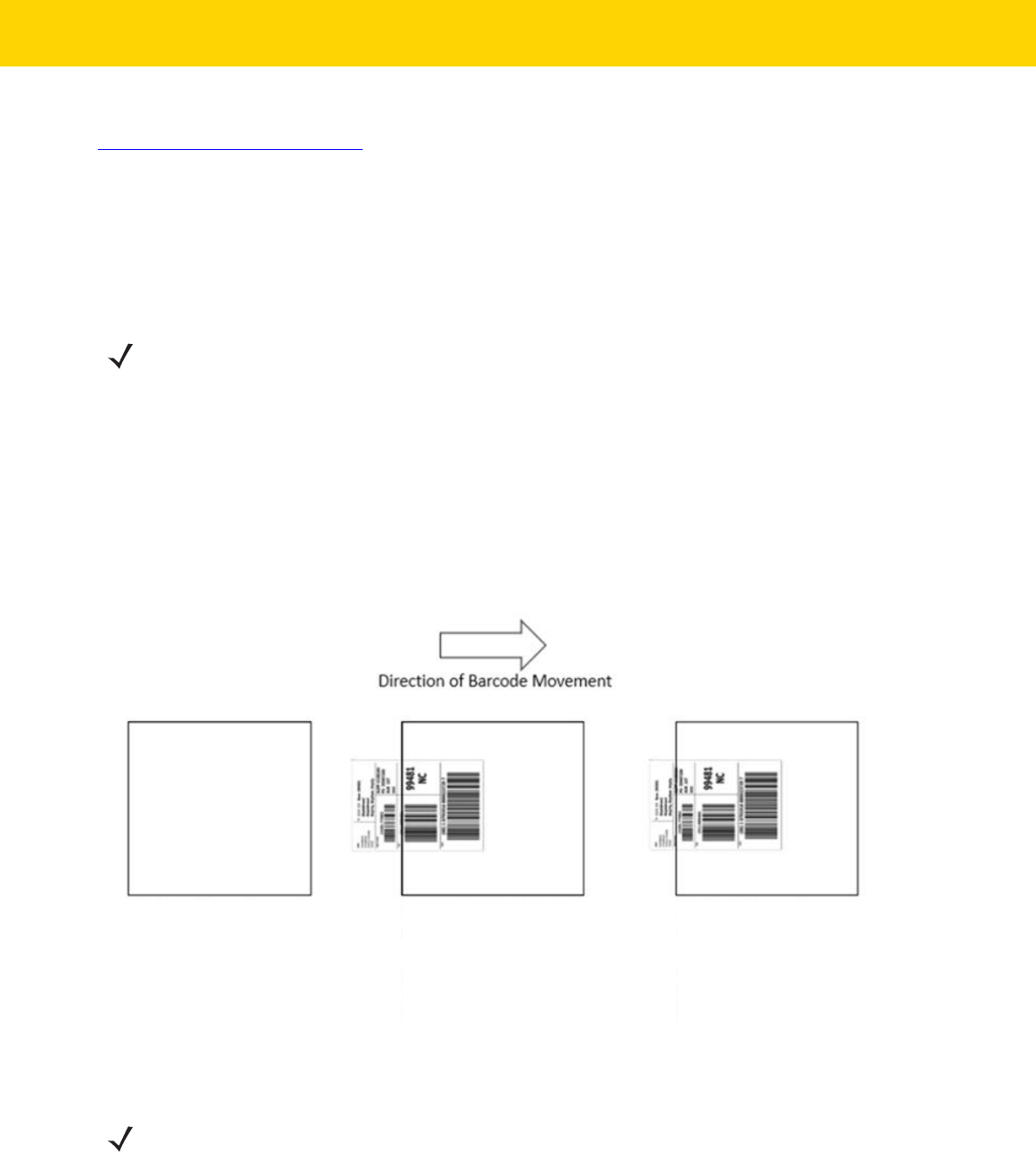
16 - 2 DS8178 Digital Scanner Product Reference Guide
To watch a video on Creating an Multicode Data Formatting (MDF) Rule using 123Scan, go to:
zebra.com/ScannerHowToVideos
.
MDF in Hands-Free Mode
MDF in a hands-free scanning mode may yield multiple unexpected and undesired outputs when a label (most
likely on a complex label) passes through the scanner's field of view. This problem happens when the complex
label’s barcodes can be matched by more than one group (for example, Group 1 represents all barcodes present
and Group 2 represent some barcodes present).
The problem is demonstrated in Figure 16-1 and as follows:
1. As the label is moving through the field of view, it is first partially read (some of the barcodes in the field of view
in Frame 2).
2. Then, the second decode occurs as it is fully read (all the barcodes in the field of view in Frame 3).
3. This yields two different outputs (instead of the expected single output) from the presentation of a label. This
problem is driven by a complex label inadvertently matching two different MDF rules/groups, thereby yielding
two outputs.
Figure 16-1 Scanning Label in a Horizontal Orientation
NOTE A similar problem can also occur in the hand-held trigger mode. If multiple MDF rules/groups exist and all
the label is not in the field of view when pressing the trigger, the output may vary depending on which MDF
rules/groups match.
Field of View - Frame 1
No label in field of view
Field of View - Frame 2
2 Barcodes Visible
Partial label in field of view
Match MDF Rule for Group 2
Output 2 barcodes
Field of View - Frame 3
3 Barcodes Visible
Full label in field of view
Match MDF Rule for Group 1
Output 3 barcodes
NOTE To minimize issues associated with MDF hands-free mode, see MDF Best Practices on page 16-3.

Data Formatting: ADF, MDF, Preferred Symbol, Data Parsing 16 - 3
MDF Best Practices
Suggestions to minimize the undesired multiple outputs during the MDF scanning in hands-free mode are as
follows:
•
Scan barcodes in a vertical orientation (see Figure 16-2).
Figure 16-2 Scanning Label in a Vertical Orientation
•
When creating the MDF programming with multiple groups, the Group 1's pattern match should be the
most complicated (hardest to match), which equals to the most number of barcodes and criteria. Then
Group 2, 3, and so on should be progressively matched more easily.
•
When defining criteria, avoid enabling an output when the pattern is not matched. Set Output if NO
pattern match set as Discard bar code (see Figure 16-3).
Figure 16-3 Figure Match Setting for Output
Discard bar code

16 - 4 DS8178 Digital Scanner Product Reference Guide
•
Select Discard barcode(s) NOT within the pattern match in the 123Scan MDF setting. For more details,
select What is this? located next to this selection.
•
To prevent double decodes of the same symbol, increase the Timeout Between Same Symbols setting.
SeeTimeout Between Decodes, Same Symbol on page 6-33 for more details.
•
Turn the scanner's aimer on to assist operators in scanning the barcode in a more consistent manner.
•
Other reasons a label/barcode may not be decoded while in the field of view are as follows:
•
The label out of focus (too close or too far away). See Decode Ranges on page 3-10 for correct working
range.
•
Specular reflection (reflection off a shiny surface).
•
The label is presented at extreme angle to scanner.
Preferred Symbol
Preferred Symbol is a bar code prioritization technique that enables favored decoding of a high priority bar code(s).
The Preferred Symbol is the only bar code that is decoded and output within the preset Preferred Symbol Timeout.
During this time, the scanner attempts to decode the prioritized bar code and reports only this bar code.
For more information, refer to the guide Multicode Data Formatting and Preferred Symbol, p/n MN-002895-xx.
To program Preferred Symbol via 123Scan, select 123Scan > Configuration Wizard > Symbologies screen, and
then select Preferred Symbol from the drop-down menu. Below are the Preferred Symbol programming options
within 123Scan.

Data Formatting: ADF, MDF, Preferred Symbol, Data Parsing 16 - 5
Data Parsing (UDI Scan+, Label Parse+ and Blood Bag Parse+)
Data Parsing allows a Zebra scanner to scan a UDI label, GS1 label, or Blood Bags with one or more barcodes
encoded with multiple data fields (such as date of manufacture, expiration date, batch number, GTIN, and SSCC)
and transmit select data fields and not others, in a specific order to a host application. Simply wave the scanner
over all the barcodes while holding the trigger and the scanner takes care of the rest.
The scanner finds and transmits only the required data fields, even if they are spread across multiple barcodes and
on different sides of the container. In addition, the scanner can insert field separators (such as tab, enter, and
slash) to automate data entry into a host application.
Pr
ogramming your scanner is easy using 123Scan’s intuitive drag and drop interface. For more information on
writing a Data Parsing Rule, refer to the Data Parsing (UDI, GS1 Label, Blood Bag) on Zebra Scanners User Guide
available at: zebra.com/support
.
To watch a video on Creating a Data Parsing Rule using 123Scan, go to: zebra.com/ScannerHowToVideos
.
Scan a UDI Label using UDI Scan+
Government regulatory agencies
1
have established Unique Device Identification (UDI) standards to identify and
monitor the distribution and use of medical devices within healthcare environments. These UDI standards identify
medical devices from manufacturing through distribution to patient use - enabling complete traceability of the
millions of individual medical devices utilized for patient care. To enable UDI compliance, all medical devices must
ca
rry a UDI label to enable “track and trace” from the point of production, during shipment, through the product’s
use and disposal.
Scan a GS1 Label using Label Parse+
The GS1 Organization, an international standards body, has released specifications used worldwide for generating
shipping labels. These labels are used when shipping packages (logistics), raw materials and produce.
Scan a Blood Bag Label using Blood Bag Parse+
The ICCBBA Organization, an international standards body, has released a specification used worldwide for
generating blood bag labels. These labels are used when shipping, storing and using blood bags. For more
information, go to: iccbba.org/tech-library/iccbba-documents/standards-documents/standard-labeling-blood2
.
NOTE:
1
United States Food and Drug Administration (FDA), European Commission, International
Medical Device Regulatory Forum
.

16 - 6 DS8178 Digital Scanner Product Reference Guide

CHAPTER 17 OCR PROGRAMMING
Introduction
This chapter describes how to set up the scanner for OCR programming. The scanner can read 6 to 60 point OCR
typeface. It supports font types OCR-A, OCR-B, MICR E13B, and US Currency Serial Number.
OCR is not as secure as a bar code. To decrease OCR misdecodes and speed OCR reading, set an accurate OCR
template and character subset, and use a check digit.
All OCR fonts are disabled by default. Enabling OCR could slow bar code decoding. You can enable OCR-A and
OCR-B at the same time, but not other combined font types.
Setting Parameters
To set feature values, scan a single bar code or a short bar code sequence. The settings are stored in non-volatile
memory and are preserved even when the imager powers down.
To return all features to default values, scan the Default Parameters on page 6-5. Throughout the programming bar
code menus, asterisks (
*) indicate default values.
NOTE Most computer monitors allow scanning bar codes directly on the screen. When scanning from the screen,
be sure to set the document magnification to a level where you can see the bar code clearly, and bars
and/or spaces do not merge.
*Enable Parameter
(1)
Feature/option
* Indicates default
Option value

17 - 2 DS8178 Digital Scanner Product Reference Guide
Scanning Sequence Examples
In most cases scanning one bar code sets the parameter value. For example, to enable OCR-B, scan the Enable
OCR-B bar code under OCR-B on page 17-5. The scanner issues a fast warble beep and the LED turns green,
signifying a successful parameter entry.
Other parameters require scanning several bar codes. See the parameter descriptions for this procedure.
Errors While Scanning
Unless otherwise specified, to correct an error during a scanning sequence, just re-scan the correct parameter.
OCR Parameter Defaults
Table 17-1 lists the defaults for OCR parameters. Change these values in one of two ways:
•
Scan the appropriate bar codes in this chapter. The new value replaces the standard default value in
memory. To recall default parameter values, see Default Parameters on page 6-5.
•
Configure the scanner using the 123Scan
configuration program. See Chapter 2, 123Scan and Software
Tools.
NOTE See Appendix A, Standard Parameter Defaults for all user preference, host, symbology, and
miscellaneous default parameters.
Table 17-1 OCR Programming Default Table
Parameter
Parameter
Number
SSI Number Default Page Number
OCR Programming Parameters
OCR-A 680 F1h A8h Disable
17-3
OCR-A Variant 684 F1h ACh OCR-A Full ASCII
17-4
OCR-B 681 F1h A9h Disable
17-5
OCR-B Variant 685 F1h ADh OCR-B Full ASCII
17-6
MICR E13B 682 F1h AAh Disable
17-10
US Currency 683 F1h ABh Disable
17-11
OCR Orientation 687 F1h AFh
0
o
17-11
OCR Lines 691 F1h B3h 1
17-13
OCR Minimum Characters 689 F1h B1h 3
17-13
OCR Maximum Characters 690 F1h B2h 100
17-14
OCR Subset 686 F1h AEh Selected font
variant
17-14
OCR Quiet Zone 695 F1h B7h 50
17-15

OCR Programming 17 - 3
OCR Programming Parameters
OCR-A
Parameter # 680 (SSI # F1h A8h)
Scan one of the following bar codes to enable or disable OCR-A.
OCR Template 547 F1h 23h 99999999
17-15
OCR Check Digit Modulus 688 F1h B0h 1
17-25
OCR Check Digit Multiplier 700 F1h BCh 121212121212
17-26
OCR Check Digit Validation 694 F1h B6h None
17-27
Inverse OCR 856 F2h 58h Regular
17-32
OCR Redundancy 1770 F8h 06h EAh Level 1
17-33
Table 17-1 OCR Programming Default Table (Continued)
Parameter
Parameter
Number
SSI Number Default Page Number
NOTE OCR is not as secure as a bar code. To decrease OCR misdecodes and speed OCR reading, set an
accurate OCR template and character subset, and use a check digit. See OCR Subset on page 17-14 and
OCR Template on page 17-15.
Enable OCR-A
(1)
*Disable OCR-A
(0)
17 - 4 DS8178 Digital Scanner Product Reference Guide
OCR-A Variant
Parameter # 684 (SSI # F1 ACh)
The font variant sets a processing algorithm and default character subset for the given font. To choose a variant,
scan one of the following bar codes. Select the most appropriate font variant to optimize performance and
accuracy.
OCR-A supports the following variants:
•
OCR-A Full ASCII
!"#$()*+,-./0123456789<>ABCDEFGHIJKLMNOPQRSTUVWXYZ\^
•
OCR-A Reserved 1
$*+-./0123456789ABCDEFGHIJKLMNOPQRSTUVWXYZ
•
OCR-A Reserved 2
$*+-./0123456789<>ABCDEFGHIJKLMNOPQRSTUVWXYZ
•
OCR-A Banking
-0123456789<>
Special banking characters output as the following representative characters:
outputs as f
outputs as c
outputs as h
NOTE Enable OCR-A before setting this parameter. If disabling OCR-A, set the variant to its default
(OCR-A Full ASCII).
*OCR-A Full ASCII
(0)
OCR-A Reserved 1
(1)

OCR Programming 17 - 5
OCR-B
Parameter # 681 9SSI # F1h A9h)
Scan one of the following bar codes to enable or disable OCR-B.
OCR-A Variant (continued)
OCR-A Reserved 2
(2)
OCR-A Banking
(3)
NOTE OCR is not as secure as a bar code. To decrease OCR misdecodes and speed OCR reading, set an
accurate OCR template and character subset, and use a check digit. See OCR Subset on page 17-14 and
OCR Template on page 17-15.
Enable OCR-B
(1)
*Disable OCR-B
(0)

17 - 6 DS8178 Digital Scanner Product Reference Guide
OCR-B Variant
Parameter # 685 (SSI # F1h ADh)
OCR-B has the following variants. Select the most appropriate font variant to optimize performance and accuracy.
•
OCR-B Full ASCII
!#$%()*+,-./0123456789<>ABCDEFGHIJKLMNOPQRSTUVWXYZ^|Ñ
•
OCR-B Banking
#+-0123456789<>JNP|
•
OCR-B Limited
+,-./0123456789<>ACENPSTVX
•
OCR-B ISBN 10-Digit Book Numbers
-0123456789>BCEINPSXz
•
OCR-B ISBN 10 or 13-Digit Book Numbers
-0123456789>BCEINPSXz
•
OCR-B Travel Document Version 1 (TD1) 3-Line ID Cards
-0123456789<ABCDEFGHIJKLMNOPQRSTUVWXYZ
•
OCR-B Travel Document Version 2 (TD2) 2-Line ID Cards
-0123456789<ABCDEFGHIJKLMNOPQRSTUVWXYZ
•
OCR-B Travel Document 2 or 3-Line ID Cards Auto-Detect
!#$%()*+,-./0123456789<>ABCDEFGHIJKLMNOPQRSTUVWXYZ^|Ñ
•
OCR-B Passport
-0123456789<ABCDEFGHIJKLMNOPQRSTUVWXYZÑ
•
OCR-B Visa Type A
-0123456789<ABCDEFGHIJKLMNOPQRSTUVWXYZ
•
OCR-B Visa Type B
-0123456789<ABCDEFGHIJKLMNOPQRSTUVWXYZÑ
•
OCR-B ICAO Travel Documents
This allows reading either TD1, TD2, Passport, Visa Type A, or Visa Type B without switching between
these options. It automatically recognizes the travel document read.
Scanning any ISBN Book Number automatically applies the appropriate ISBN checksum.

OCR Programming 17 - 7
To choose a variant, scan one of the bar codes below. Selecting the following OCR-B variants automatically sets
the appropriate OCR Lines on page 17-13. These five variants invoke extensive special algorithms and checking
for that particular document type:
Variant OCR Lines Setting
Passport 2
TD1 ID Cards 3
TD2 ID Cards 2
Visa Type A 2
Visa Type B 2
NOTE When setting one of the variants above with both OCR-A and OCR-B enabled, the scanner reads the
specified travel document but does not read OCR-A. When the OCR-B variant is set back to the default
(OCR-B Full ASCII), the scanner reads OCR-A.
NOTE Enable OCR-B before setting this parameter. If disabling OCR-B, set the variant to its default
(OCR-B Full ASCII).
*OCR-B Full ASCII
(0)
OCR-B Banking
(1)
OCR-B Limited
(2)
OCR-B ISBN 10-Digit Book Numbers
(6)

17 - 8 DS8178 Digital Scanner Product Reference Guide
OCR-B Variant (continued)
OCR-B ISBN 10 or 13-Digit Book Numbers
(7)
OCR-B Travel Document Version 1 (TD1)
3 Line ID Cards
(3)
OCR-B Travel Document Version 2 (TD2)
2-Line ID Cards
(8)
Travel Document 2 or 3-Line ID Cards Auto-Detect
(20)
OCR-B Passport
(4)

OCR Programming 17 - 9
OCR-B Variant (continued)
OCR-B Visa Type A
(9)
OCR-B Visa Type B
(10)
OCR-B ICAO Travel Documents
(11)

17 - 10 DS8178 Digital Scanner Product Reference Guide
MICR E13B
Parameter # 682 (SSI # F1h AAh)
Scan one of the following bar codes to enable or disable MICR E13B.
MICR E 13B uses the following characters:
TOAD characters (Transit, On Us, Amount, and Dash) output as the following representative characters:
outputs as
t
outputs as a
outputs as o
outputs as d
NOTE OCR is not as secure as a bar code. To decrease OCR misdecodes and speed OCR reading, set an
accurate OCR template and character subset, and use a check digit. See OCR Subset on page 17-14 and
OCR Template on page 17-15.
Enable MICR E13B
(1)
*Disable MICR E13B
(0)

OCR Programming 17 - 11
US Currency Serial Number
Parameter # 683 (SSI # F1h ABh)
Scan one of the following bar codes to enable or disable US Currency Serial Number.
OCR Orientation
Parameter # 687 (SSI # F1h AFh)
Select one of five options to specify the orientation of the OCR to read:
•
0
o
to the imaging engine (default)
•
270
o
clockwise (or 90
o
counterclockwise) to the imaging engine
•
180
o
(upside down) to the imaging engine
•
90
o
clockwise to the imaging engine
•
Omnidirectional
Setting an incorrect orientation can cause misdecodes.
NOTE OCR is not as secure as a bar code. To decrease OCR misdecodes and speed OCR reading, set an
accurate OCR template and character subset, and use a check digit. See OCR Subset on page 17-14 and
OCR Template on page 17-15.
Enable US Currency
(1)
*Disable US Currency
(0)

17 - 12 DS8178 Digital Scanner Product Reference Guide
OCR Orientation (continued)
*OCR Orientation 0
o
(0)
OCR Orientation 270
o
Clockwise
(1)
OCR Orientation 180
o
Clockwise
(2)
OCR Orientation 90
o
Clockwise
(3)
OCR Orientation Omnidirectional
(4)

OCR Programming 17 - 13
OCR Lines
Parameter # 691 (SSI # F1h B3h)
To select the number of OCR lines to decode, scan one of the following bar codes. Selecting Visas, TD1, or TD2 ID
cards automatically sets the appropriate
OCR Lines. Also see OCR-B Variant on page 17-6.
OCR Minimum Characters
Parameter # 689 (SSI # F1h B1h)
To select the minimum number of OCR characters (not including spaces) per line to decode, scan the following bar
code, then scan a three-digit number between 003 and 100 using the bar codes in Appendix G, Numeric Bar Codes
representing the number of OCR characters to decode. Strings of OCR characters less than the minimum are
ignored. The default is 003.
*OCR 1 Line
(1)
OCR 2 Lines
(2)
OCR 3 Lines
(3)
OCR Minimum Characters

17 - 14 DS8178 Digital Scanner Product Reference Guide
OCR Maximum Characters
Parameter # 690 (SSI # F1h B2h)
To select the maximum number of OCR characters (including spaces) per line to decode, scan the following bar
code, then scan a three-digit number between 003 and 100 using the bar codes in Appendix G, Numeric Bar Codes
representing the number of OCR characters to decode. Strings of OCR characters greater than the maximum are
ignored. The default is 100.
OCR Subset
Parameter # 686 (SSI # F1h AEh)
Create an OCR subset to define a custom group of characters in place of a preset font variant. For example, if
scanning only numbers and the letters A, B, and C, create a subset of just these characters to speed decoding.
This applies a designated OCR Subset across all enabled OCR fonts.
To set or modify the OCR font subset:
1. Enable the appropriate OCR font(s).
2. Scan the OCR Subset bar code.
3. Scan numbers and letters to form the OCR Subset from Appendix H, Alphanumeric Bar Codes.
4. Scan End of Message on page H-7.
To cancel an OCR subset, for OCR-A or OCR-B, scan OCR-A variant
Full ASCII, or OCR-B variant Full ASCII.
For MICR E13B or US Currency Serial Number, create a subset which includes all allowed characters in that
character set, or scan an option from the Default Parameters on page 6-5 and re-program the scanner.
OCR Maximum Characters
OCR Subset

OCR Programming 17 - 15
OCR Quiet Zone
Parameter # 695 (SSI # F1h B7h)
This option sets the OCR quiet zone. The scanner stops scanning a field when it detects a sufficiently wide blank
space. The width of this space is defined by the End of Field option. Used with parsers that tolerate slanted
characters, the End of Field count is approximately a count of 8 for a character width. For example, if set to 15,
then two character widths are an end of line indicator for the parser. Larger end of field numbers require bigger
quiet zones at each end of text line.
To set a quiet zone, scan the following bar code, then scan a two-digit number using the numeric keypad in
Appendix G, Numeric Bar Codes. The range of the quiet zone is 20 - 99 and the default is 50, indicating a six
character width quiet zone.
OCR Template
Parameter # 547 (SSI # F1h 23h)
This option creates a template for precisely matching scanned OCR characters to a desired input format.
Appropriate OCR template needs to be set before using OCR features.
To set or modify the OCR decode template, scan the OCR Template bar code, and then scan bar codes on the
following pages that correspond to numbers and letters to form the template expression. Then scan
End of
Message
. The default is 99999999 which accepts OCR strings only containing eight digits.
OCR Quiet Zone
OCR Template
End of Message

17 - 16 DS8178 Digital Scanner Product Reference Guide
Required Digit (9)
Only a numeric character is accepted in this position.
Template Valid data Valid data Invalid data
99999 12987 30517 123AB
Required Alpha (A)
Only an alpha character is accepted in this position.
Template Valid data Valid data Invalid data
AAAAA ABCDE UVWXY 12FGH
Optional Alphanumeric (1)
An alphanumeric character is accepted in this position if present. Optional characters are not allowed as the first
character(s) in a field of like characters.
Template Valid data Valid data Invalid data
99991 1234A 12345 1234<
9
A
1

OCR Programming 17 - 17
Optional Alpha (2)
An alpha character is accepted in this position if present. Optional characters are not allowed as the first
character(s) in a field of like characters.
Template Valid data Valid data Invalid data
AAAA2 ABCDE WXYZ ABCD6
Alpha or Digit (3)
An alphanumeric character is required in this position to validate the incoming data.
Template Valid data Valid data Invalid data
33333 12ABC WXY34 12AB<
Any Including Space & Reject (4)
Any character is accepted in this position, including space and reject. It cannot be the first place in a template. An
underscore (_) represents rejects in the output. This is a good selection for troubleshooting.
Template Valid data Valid data
99499 12$34 34 98
2
3
4

17 - 18 DS8178 Digital Scanner Product Reference Guide
Any except Space & Reject (5)
Any character is accepted in this position, except a space or reject.
Template Valid data Valid data Invalid data
55999 A.123 *Z456 A BCD
Optional Digit (7)
A numeric character is accepted if present. Optional characters are not allowed as the first character(s) in a field of
like characters.
Template Valid data Valid data Invalid data
99977 12345 789 789AB
Digit or Fill (8)
Any numeric or fill character is accepted in this position.
Template Valid data Valid data Valid data
88899 12345 >>789 <<789
5
7
8

OCR Programming 17 - 19
Alpha or Fill (F)
Any alpha or fill character is accepted in this position.
Template Valid data Valid data Valid data
AAAFF ABCXY LMN>> ABC<5
Optional Space ( )
A space is accepted if present. Optional characters are not allowed as the first character(s) in a field of like
characters.
Template Valid data Valid data Invalid data
99 99 12 34 1234 67891
Optional Small Special (.)
A special character is accepted if present. Optional characters are not allowed as the first character(s) in a field of
like characters. Small special characters are - , and .
Template Valid data Valid data Invalid data
AA.99 MN.35 XY98 XYZ12
F
Space
.

17 - 20 DS8178 Digital Scanner Product Reference Guide
Other Template Operators
These template operators assist in capturing, delimiting, and formatting scanned OCR data.
Literal String (" and +)
Use either of these delimiting characters surrounding characters from the alphanumeric keyboard in Appendix H,
Alphanumeric Bar Codes to define a literal string within a template that must be present in scanned OCR data.
There are two characters used to delimit required literal strings; if one of the delimiter characters is present in the
desired literal string, use the other delimiter.
Template Valid data Invalid data
"35+BC" 35+BC AB+22
New Line (E)
To create a template of multiple lines, add E between the template of each single line.
Template Valid data Valid data Invalid data
999EAAAA 321 987 XYZW
BCAD ZXYW 12
“
+
E

OCR Programming 17 - 21
String Extract (C)
This operator combined with others defines a string of characters to extract from the scanned data. The string
extract is structured as follows:
CbPe
Where:
•
C is the string extract operator
•
b is the string begin delimiter
•
P is the category (one or more numeric or alpha characters) describing the string representation
•
e is the string end delimiter
Values for b and e can be any scannable character. They are included in the output stream.
Template Incoming data Output
C>A> XQ3>ABCDE> >ABCDE>
->ATHRUZ>123 >ATHRUZ>
1ABCZXYZ No Output
Ignore to End of Field (D)
This operator causes all characters after a template to be ignored. Use this as the last character in a template
expression. Examples for the template 999D:
Template Incoming data Output
999D 123-PED 123
357298 357
193 193
C
D

17 - 22 DS8178 Digital Scanner Product Reference Guide
Skip Until (P1)
This operator skips over characters until a specific character type or a literal string is detected. It can be used in two
ways:
P1ct
Where:
•
P1 is the Skip Until operator
•
c is the type of character that triggers the start of output
•
t is one or more template characters
P1"s"t
Where:
•
P1 is the Skip Until operator
•
"s" is one or more literal string characters (see Literal String (" and +) on page 17-20) that trigger the start of
output
•
t is one or more template characters
The trigger character or literal string is included in output from a Skip Until operator, and the first character in the
template should accommodate this trigger.
Template Incoming data Output
P1"PN"AA9999 123PN9876 PN9876
PN1234 PN1234
X-PN3592 PN3592
P
1

OCR Programming 17 - 23
Skip Until Not (P0)
This operator skips over characters until a specific character type or a literal string is not matched in the output
stream. It can be used in two ways:
P0ct
Where:
•
P0 is the Skip Until Not operator
•
c is the type of character that triggers the start of output
•
t is one or more template characters
P0"s"t
Where:
•
P0 is the Skip Until Not operator
•
"s" is one or more literal string characters (see Literal String (" and +) on page 17-20) that trigger the start
of output
•
t is one or more template characters
The trigger character or literal string is not included in output from a Skip Until Not operator.
Template Incoming data Output
P0A9999 BPN3456 3456
PN1234 1234
5341 No output
Template Incoming data Output
P0"PN"9999 PN3456 3456
5341 No output
PNPN7654 7654
P
0

17 - 24 DS8178 Digital Scanner Product Reference Guide
Repeat Previous (R)
This operator allows a template character to repeat one or more times, allowing the capture of variable-length
scanned data. The following examples capture two required alpha characters followed by one or more required
digits:
Template Incoming data Output
AA9R AB3 AB3
PN12345 PN12345
32RM52700 No output
Scroll Until Match (S)
This operator steps through scanned data one character at a time until the data matches the template.
Template Incoming data Output
S99999 AB3 No Output
PN12345 12345
32RM52700 52700
R
S

OCR Programming 17 - 25
Multiple Templates
This feature sets up multiple templates for OCR decoding. To do this, follow the procedure described in OCR
Template on page 17-15 (scan the OCR Template bar code, and then bar codes corresponding to numbers and
letters to form the template expression, and then
End of Message) for each template in the multiple template string,
using a capital letter X as a separator between templates.
For example, set the OCR Template as 99999XAAAAA to decode OCR strings of either 12345 or ABCDE.
Template Examples
Following are sample templates with descriptions of valid data for each definition.
Field Definition Description
"M"99977
M followed by three digits and two optional digits.
"X"997777"X"
X followed by two digits, four optional digits, and an X.
9959775599 Two digits followed by any character, a digit, two optional digits, any two characters,
and two digits.
A55"-"999"-"99 A letter followed by two characters, a dash, three digits, a dash, and two digits.
33A"."99 Two alphanumeric characters followed by a letter, a period, and two digits.
999992991 Five digits followed by an optional alpha, two digits, and an optional alphanumeric.
"PN98" Literal field -
PN98
OCR Check Digit Modulus
Parameter # 688 (SSI # F1h B0h)
The check digit is the last digit (in the right-most position) in an OCR string and improves the accuracy of the
collected data. This option sets OCR module check digit calculation. The calculation is performed on incoming data
to determine this check digit, based on the numeric weight of the alpha and numeric characters. See OCR Check
Digit Multiplier on page 17-26. If the incoming data does not match the check digit, the data is considered corrupt.
The selected check digit option does not take effect until you set OCR Check Digit Validation on page 17-27.
To choose the Check Digit Modulus, such as 10 for Modulus 10, scan the following bar code, and then scan a
three-digit number from 001 to 099 representing the check digit using the numeric keypad in Appendix G, Numeric
Bar Codes. The default is
1.
OCR Check Digit

17 - 26 DS8178 Digital Scanner Product Reference Guide
OCR Check Digit Multiplier
Parameter # 700 (SSI # F1h BCh)
This option sets OCR check digit multipliers for character positions. For check digit validation, each character in
scanned data has an assigned weight to use in calculating the check digit. The scanner OCR ships with the
following weight equivalents:
0 = 0 A = 10 K = 20 U = 30
1 = 1 B = 11 L = 21 V = 31
2 = 2 C = 12 M = 22 W = 32
3 = 3 D = 13 N = 23 X = 33
4 = 4 E = 14 O = 24 Y = 34
5 = 5 F = 15 P = 25 Z = 35
6 = 6 G = 16 Q = 26 Space = 0
7 = 7 H = 17 R = 27
8 = 8 I = 18 S = 28
9 = 9 J = 19 T = 29
All other characters are equivalent to one (1).
You can define the multiplier string if it is different from the default.
121212121212 (default)
123456789A (for ISBN, Product Add Right to Left. See OCR Check Digit Validation on page 17-27)
For example:
ISBN 0 2 0 1 1 8 3 9 9 4
Multiplier 10 9 8 7 6 5 4 3 2 1
Product 0 18 0 7 6 40 12 27 18 4
Product add 0+ 18+ 0+ 7+ 6+ 40+ 12+ 27+ 18+ 4= 132
ISBN uses Modulus 11 for the check digit. In this case, 132 is divisible by 11, so it passes the check digit.
To set the check digit multiplier, scan the following bar code, and then scan numbers and letters to form the
multiplier string from Appendix H, Alphanumeric Bar Codes. Then scan End of Message on page H-7.
OCR Check Digit Multiplier

OCR Programming 17 - 27
OCR Check Digit Validation
Parameter # 694 (SSI # F1h B6h)
Use the following options to protect against scanning errors by applying a check digit validation scheme.
None
No check digit validation, indicating no check digit is applied. This is the default.
Product Add Left to Right
Each character in the scanned data is assigned a numeric value (see OCR Check Digit Multiplier on page 17-26).
Each digit representing a character in the scanned data is multiplied by its corresponding digit in the multiplier, and
the sum of these products is computed. The check digit passes if this sum modulo Check Digit Modulus is zero.
Example:
Scanned data numeric value is 132456 (check digit is 6)
Check digit multiplier string is 123456
Digit 1 3 2 4 5 6
Multiplier 1 2 3 4 5 6
Product 1 6 6 16 25 36
Product add 1+ 6+ 6+ 16+ 25+ 36= 90
The Check Digit Modulus is 10. It passes because 90 is divisible by 10 (the remainder is zero).
*No Check Digit
(0)
Product Add Left to Right
(3)

17 - 28 DS8178 Digital Scanner Product Reference Guide
Product Add Right to Left
Each character in the scanned data is assigned a numeric value (see OCR Check Digit Multiplier on page 17-26).
The check digit multiplier is reversed in order. Each value representing a character in the scanned data is multiplied
by its corresponding digit in the reversed multiplier, resulting in a product for each character in the scanned data.
The sum of these products is computed. The check digit passes if this sum modulo Check Digit Modulus is zero.
Example:
Scanned data numeric value is 132459 (check digit is 9)
Check digit multiplier string is 123456
Digit 1 3 2 4 5 9
Multiplier 6 5 4 3 2 1
Product 6 15 8 12 10 9
Product add 6+ 15+ 8+ 12+ 10+ 9= 60
The Check Digit Modulus is 10. It passes because 60 is divisible by 10 (the remainder is 0).
Digit Add Left to Right
Each character in the scanned data is assigned a numeric value (see OCR Check Digit Multiplier on page 17-26).
Each value representing a character in the scanned data is multiplied by its corresponding digit in the multiplier,
resulting in a product for each character in the scanned data. The sum of each individual digit in all of the products
is then calculated. The check digit passes if this sum modulo Check Digit Modulus is zero.
Example:
Scanned data numeric value is 132456 (check digit is 6)
Check digit multiplier string is 123456
Digit 1 3 2 4 5 6
Multiplier 1 2 3 4 5 6
Product 1 6 6 16 25 36
Digit add 1+ 6+ 6+ 1+6+ 2+5+ 3+6= 36
The Check Digit Modulus is 12. It passes because 36 is divisible by 12 (the remainder is 0).
Product Add Right to Left
(1)
Digit Add Left to Right
(4)

OCR Programming 17 - 29
Digit Add Right to Left
Each character in the scanned data is assigned a numeric value (see OCR Check Digit Multiplier on page 17-26).
The check digit multiplier is reversed in order. Each value representing a character in the scanned data is multiplied
by its corresponding digit in the reversed multiplier, resulting in a product for each character in the scanned data.
The sum of each individual digit in all of the products is then calculated. The check digit passes if this sum modulo
Check Digit Modulus is zero.
Example:
Scanned data numeric value is 132456 (check digit is 6)
Check digit multiplier string is 123456
Digit 1 3 2 4 5 6
Multiplier 6 5 4 3 2 1
Product 6 15 8 12 10 6
Digit add 6+ 1+5+ 8+ 1+2+ 1+0+ 6= 30
The Check Digit Modulus is 10. It passes because 30 is divisible by 10 (the remainder is 0).
Product Add Right to Left Simple Remainder
Each character in the scanned data is assigned a numeric value (see OCR Check Digit Multiplier on page 17-26).
The check digit multiplier is reversed in order. Each value representing a character in the scanned data is multiplied
by its corresponding digit in the reversed multiplier, resulting in a product for each character in the scanned data.
The sum of these products
except for the check digit's product is computed. The check digit passes if this sum
modulo Check Digit Modulus is equal to the check digit's product.
Example:
Scanned data numeric value is 122456 (check digit is 6)
Check digit multiplier string is 123456
Digit 1 2 2 4 5 6
Multiplier 6 5 4 3 2 1
Product 6 10 8 12 10 6
Product add 6+ 10+ 8+ 12+ 10= 46 6
The Check Digit Modulus is 10. It passes because 46 divided by 10 leaves a remainder of 6.
Digit Add Right to Left
(2)
Product Add Right to Left Simple Remainder
(5)

17 - 30 DS8178 Digital Scanner Product Reference Guide
Digit Add Right To Left Simple Remainder
Each character in the scanned data is assigned a numeric value (see OCR Check Digit Multiplier on page 17-26).
The check digit multiplier is reversed in order. Each value representing a character in the scanned data is multiplied
by its corresponding digit in the reversed multiplier, resulting in a product for each character in the scanned data.
The sum of each individual digit in all of the products
except for the check digit's product is then calculated. The
check digit passes if this sum modulo Check Digit Modulus is equal to the check digit's product.
Example:
Scanned data numeric value is 122459 (check digit is 6)
Check digit multiplier string is 123456
Digit 1 2 2 4 5 9
Multiplier 6 5 4 3 2 1
Product 6 10 8 12 10 9
Digit add 6+ 1+0+ 8+ 1+2+ 1+0= 19 9
The Check Digit Modulus is 10. It passes because 19 divided by 10 leaves a remainder of 9.
Digit Add Right to Left Simple Remainder
(6)

OCR Programming 17 - 31
Health Industry - HIBCC43
This is the health industry module 43 check digit standard. The check digit is the modulus 43 sum of all the
character values in a given message, and is printed as the last character in a given message.
Example:
Supplier Labeling Data Structure: + A 1 2 3 B J C 5 D 6 E 7 1
Sum of values: 41+10+1+2+3+11+19+12+5+13+6+14+7+1 = 145
Divide 145 by 43. The quotient is 3 with a remainder of 16. The check digit is the character corresponding to the
value of the remainder (see Table 17-2), which in this example is 16, or G. The complete Supplier Labeling Data
Structure, including the check digit, therefore is:
A 1 2 3 B J C 5 D 6 E 7 1 G
Table 17-2 Table of Numeric Value Assignments for Computing HIBC LIC Data Format Check Digit
0 = 0 9 = 9 I = 18 R = 27 - = 36
1 = 1 A = 10 J = 19 S = 28 . = 37
2 = 2 B = 11 K = 20 T = 29 Space = 38
3 = 3 C = 12 L = 21 U =30 $ = 39
4 = 4 D = 13 M = 22 V = 31 / = 40
5 = 5 E = 14 N = 23 W = 32 + = 41
6 = 6 F = 15 O = 24 X = 33 % = 42
7 = 7 G = 16 P = 25 Y = 34
8 = 8 H = 17 Q = 26 Z = 35
Health Industry - HIBCC43
(9)

17 - 32 DS8178 Digital Scanner Product Reference Guide
Inverse OCR
Parameter # 856 (SSI # F2h 58h)
Inverse OCR is white or light words on a black or dark background. Select an option for decoding inverse OCR:
•
Regular Only - Decode regular OCR (black on white) strings only.
•
Inverse Only - Decode inverse OCR (white on black) strings only.
•
Autodiscriminate - Decode both regular and inverse OCR strings.
*Regular Only
(0)
Inverse Only
(1)
Autodiscriminate
(2)

OCR Programming 17 - 33
OCR Redundancy
Parameter # 1770 (SSI # F8h 06h EAh)
This option adjusts the number of times to decode an OCR text string before transmission. There are three levels
of OCR decode redundancy. There is an inverse relationship between the redundancy level and OCR decoding
aggressiveness. Increasing the level of the redundancy can reduce OCR scanning aggressiveness, so select only
the level of redundancy necessary.
•
OCR Redundancy Level 1: This default setting allows the digital scanner to operate in its most aggressive
state while providing sufficient accuracy in decoding most in-spec OCR text strings.
•
OCR Redundancy Level 2: This setting eliminates most misdecodes while maintaining reasonable
aggressiveness.
•
OCR Redundancy Level 3: Select this option with greater redundancy requirements if OCR Redundancy
Level 2 fails to eliminate misdecodes.
*OCR Redundancy Level 1
(1)
OCR Redundancy Level 2
(2)
OCR Redundancy Level 3
(3)

17 - 34 DS8178 Digital Scanner Product Reference Guide
CHAPTER 18 DRIVER’S LICENSE SET
UP (DS8178-DL)
Introduction
The DS8178-DL digital scanner is capable of parsing out information from standard US driver's licenses and
certain other American Association of Motor Vehicle Administrators (AAMVA) compliant ID cards. This is achieved
using internally embedded algorithms, where scanning bar codes activates algorithms internally embedded in the
digital scanner to produce formatted data. Use the formatted data for age verification, credit card application
information, and more.
This chapter describes how to program the DS8178-DL digital scanner to read and use the data contained in the
2D bar codes on US driver's licenses and AAMVA compliant ID cards.
Table 18-1 DL Parsing Parameter Table
Parameter Default
Page
Number
DL Parsing Parameters
Driver’s License Parsing No Driver’s License Parsing
18-2
Parsing Driver’s License Data Fields N/A
18-3
Driver’s License Parse Field Bar Codes N/A
18-4
AAMVA Parse Field Bar Codes N/A
18-7
Set Default Parameter N/A
18-17
Output Gender as M or F N/A
18-17
Date Format CCYYMMDD
18-18
No Separator N/A
18-19
Send Keystroke
Control Characters
Keyboard Characters
N/A
18-20
18-20
18-26
Parsing Rule Example N/A
18-41
Embedded Driver’s License Parsing ADF Example N/A
18-45

18 - 2 DS8178 Digital Scanner Product Reference Guide
Driver’s License Parsing
Parameter # 645 (SSI # F1 85)
To enable driver's license parsing on the digital scanner, scan the Embedded Driver's License Parsing bar code.
This does not require Zebra software (.DLL).
Scan the bar codes on the following pages in the order indicating the sequence of data fields that the digital
scanner outputs. See Parsing Driver’s License Data Fields (Embedded Driver's License Parsing) on page 18-3 for
more information.
*No Driver’s License Parsing
Embedded Driver’s License Parsing

Driver’s License Set Up (DS8178-DL) 18 - 3
Parsing Driver’s License Data Fields
(Embedded Driver's License Parsing)
To begin programming a parsing rule:
1. Scan Begin New Driver’s License Parse Rule on page 18-4.
2. Scan any of the field bar codes on the following pages, or Send Keystroke (Control Characters and Keyboard
Characters) on page 18-20 to complete the parsing rule.
3. After entering the entire rule, scan Save Driver’s License Parse Rule on page 18-4 to save the rule.
To abort the programming sequence at any time during programming, scan Quit Entering Driver’s License Rule on
page 18-4. Any previously saved rule is retained.
To erase a programmed saved rule, scan Erase Driver’s License Parse Rules on page 18-4.
Embedded Driver's License Parsing Criteria - Code Type
After specifying the fields and their order for the parsed driver's license, you can also apply standard ADF rules to
the parsed data using the
Parsed Driver’s License criterion bar code in the Advanced Data Formatting Programmer
Guide.
See Embedded Driver's License Parsing ADF Example on page 18-45 for a sample ADF rule using this code type
criterion.
NOTE Only ONE driver’s license parsing rule may be stored in memory at any time. Saving a new rule replaces
the prior rule.
NOTE Only create standard ADF rules on parsed driver's license data when configured for Embedded Driver's
License Parsing.

18 - 4 DS8178 Digital Scanner Product Reference Guide
Driver’s License Parse Field Bar Codes
Begin New Driver’s License Parse Rule
Save Driver’s License Parse Rule
Quit Entering Driver’s License Rule
Erase Driver’s License Parse Rules

Driver’s License Set Up (DS8178-DL) 18 - 5
Driver’s License Parse Field Bar Codes (continued)
The parse fields currently supported begin below. Not all IDs present data in the same format. For example, some IDs may
have separate fields for first name, last name, and middle initial, and others may have a single field with the entire name.
In addition, some IDs may expire on the subject's birth date and the actual expiration date field may only indicate the year.
In order to present data in a consistent format, the following nine bar codes return data that may be calculated from the
actual data contained within the ID bar code.
First Name
Middle Name/Initial
Last Name
Name Suffix
Name Prefix
Expiration Date
Birth Date

18 - 6 DS8178 Digital Scanner Product Reference Guide
Driver’s License Parse Field Bar Codes (continued)
Issue Date
ID Number (Formatted)

Driver’s License Set Up (DS8178-DL) 18 - 7
AAMVA Parse Field Bar Codes
AAMVA Issuer ID
Full Name
Last Name
First Name
Middle Name / Initial
Name Suffix
Name Prefix

18 - 8 DS8178 Digital Scanner Product Reference Guide
AAMVA Parse Field Bar Codes (continued)
Mailing Address Line 1
Mailing Address Line 2
Mailing Address City
Mailing Address State
Mailing Address Postal Code
Home Address Line 1
Home Address Line 2

Driver’s License Set Up (DS8178-DL) 18 - 9
AAMVA Parse Field Bar Codes (continued)
Home Address City
Home Address State
Home Address Postal Code
License ID Number
License Class
License Restrictions
License Endorsements

18 - 10 DS8178 Digital Scanner Product Reference Guide
AAMVA Parse Field Bar Codes (continued)
Height (Feet and/or Inches)
Height (Centimeters)
Weight (Pounds)
Weight (Kilograms)
Eye Color
Hair Color
License Expiration Date

Driver’s License Set Up (DS8178-DL) 18 - 11
AAMVA Parse Field Bar Codes (continued)
Birth Date
Gender
License Issue Date
License Issue State
Social Security Number
Permit Class
Permit Expiration Date

18 - 12 DS8178 Digital Scanner Product Reference Guide
AAMVA Parse Field Bar Codes (continued)
Permit ID Number
Permit Issue Date
Permit Restrictions
Permit Endorsements
AKA Social Security Name
AKA Full Name
AKA Last Name
AKA First Name

Driver’s License Set Up (DS8178-DL) 18 - 13
AAMVA Parse Field Bar Codes (continued)
AKA Middle Name / Initial
AKA Name Suffix
AKA Name Prefix
AKA Birth Date
Issue Timestamp
Number of Duplicates
Medical Codes

18 - 14 DS8178 Digital Scanner Product Reference Guide
AAMVA Parse Field Bar Codes (continued)
Organ Donor
Nonresident
Customer ID
Weight Range
Document Discriminator
Country
Federal Commission Codes

Driver’s License Set Up (DS8178-DL) 18 - 15
AAMVA Parse Field Bar Codes (continued)
Place of Birth
Audit Information
Inventory Control
Race / Ethnicity
Std Vehicle Class
Std Endorsements
Std Restrictions
18 - 16 DS8178 Digital Scanner Product Reference Guide
AAMVA Parse Field Bar Codes (continued)
Class Description
Endorsement Description
Restrictions Description
Height in Inches
Height in Centimeters
Parser Version ID Bar Codes
Include this field to emit embedded parser software version identification
Parser Version ID

Driver’s License Set Up (DS8178-DL) 18 - 17
User Preferences
Set Default Parameter
Scan this bar code to return all parameters to the default values listed in Table A-1 on page A-1.
Output Gender as M or F
Scan this bar code to report the gender as M or F instead of a numeric value.
*Set All Defaults
Output gender as M or F

18 - 18 DS8178 Digital Scanner Product Reference Guide
Date Format
Use these bar codes to select the date format that is displayed. Date fields include the following:
•
CCYY = 4-digit year (CC=2-digit century [00-99], YY=2-digit year in the century [00-99])
•
MM = 2-digit month [01-12]
•
DD = 2-digit day of the month [00-31]
The default is Date Format CCYYMMDD.
NOTE To specify a date separator, i.e., a character separating each field of the date, scan the Send <character>
bar code that corresponds to the alphanumeric character to use as the date separator immediately
following the date format bar code. To select no date separator, scan the No Separator DL parsing rule
immediately following the date format bar code.
*CCYYMMDD
CCYYDDMM
MMDDCCYY
MMCCYYDD
DDMMCCYY
DDCCYYMM

Driver’s License Set Up (DS8178-DL) 18 - 19
Date Format (continued)
No Separator
Scan this bar code immediately following a date format bar code to use no separator character between the date
fields.
YYMMDD
YYDDMM
MMDDYY
MMYYDD
DDMMYY
DDYYMM
No Separator

18 - 20 DS8178 Digital Scanner Product Reference Guide
Send Keystroke (Control Characters and Keyboard Characters)
Control Characters
Scan a Send bar code for the keystroke to send.
Send Control A
Send Control B
Send Control C
Send Control D
Send Control E
Send Control F
Send Control G

Driver’s License Set Up (DS8178-DL) 18 - 21
Send Control H

18 - 22 DS8178 Digital Scanner Product Reference Guide
Control Characters (continued)
Send Control I
Send Control J
Send Control K
Send Control L
Send Control M
Send Control N
Send Control O

Driver’s License Set Up (DS8178-DL) 18 - 23
Send Control P

18 - 24 DS8178 Digital Scanner Product Reference Guide
Control Characters (continued)
Send Control Q
Send Control R
Send Control S
Send Control T
Send Control U
Send Control V
Send Control W

Driver’s License Set Up (DS8178-DL) 18 - 25
Control Characters (continued)
Send Control X
Send Control Y
Send Control Z
Send Control [
Send Control \
Send Control ]

18 - 26 DS8178 Digital Scanner Product Reference Guide
Keyboard Characters
Scan a Send bar code for the keyboard characters to send.
Control Characters (continued)
Send Control 6
Send Control -
Send Space
Send !
Send “
Send #

Driver’s License Set Up (DS8178-DL) 18 - 27
Keyboard Characters (continued)
Send $
Send %
Send &
Send ‘
Send (
Send )
Send *

18 - 28 DS8178 Digital Scanner Product Reference Guide
Keyboard Characters (continued)
Send +
Send ,
Send -
Send .
Send /
Send 0
Send 1

Driver’s License Set Up (DS8178-DL) 18 - 29
Keyboard Characters (continued)
Send 2
Send 3
Send 4
Send 5
Send 6
Send 7
Send 8

18 - 30 DS8178 Digital Scanner Product Reference Guide
Keyboard Characters (continued)
Send 9
Send :
Send ;
Send <
Send =
Send >
Send ?

Driver’s License Set Up (DS8178-DL) 18 - 31
Keyboard Characters (continued)
Send @
Send A
Send B
Send C
Send D
Send E
Send F

18 - 32 DS8178 Digital Scanner Product Reference Guide
Keyboard Characters (continued)
Send G
Send H
Send I
Send J
Send K
Send L
Send M

Driver’s License Set Up (DS8178-DL) 18 - 33
Keyboard Characters (continued)
Send N
Send O
Send P
Send Q
Send R
Send S
Send T

18 - 34 DS8178 Digital Scanner Product Reference Guide
Keyboard Characters (continued)
Send U
Send V
Send W
Send X
Send Y
Send Z
Send [

Driver’s License Set Up (DS8178-DL) 18 - 35
Keyboard Characters (continued)
Send \
Send ]
Send ^
Send _
Send `
Send a
Send b

18 - 36 DS8178 Digital Scanner Product Reference Guide
Keyboard Characters (continued)
Send c
Send d
Send e
Send f
Send g
Send h
Send i

Driver’s License Set Up (DS8178-DL) 18 - 37
Keyboard Characters (continued)
Send j
Send k
Send l
Send m
Send n
Send o
Send p

18 - 38 DS8178 Digital Scanner Product Reference Guide
Keyboard Characters (continued)
Send q
Send r
Send s
Send t
Send u
Send v
Send w

Driver’s License Set Up (DS8178-DL) 18 - 39
Keyboard Characters (continued)
Send x
Send y
Send z
Send {
Send |
Send }
Send ~

18 - 40 DS8178 Digital Scanner Product Reference Guide
Keyboard Characters (continued)
Send Tab Key
Send Enter Key

Driver’s License Set Up (DS8178-DL) 18 - 41
Parsing Rule Example
Scan the following bar codes in sequence to program the digital scanner to extract and transmit first, middle, and
last names; mailing address line 1; mailing address line 2; mailing address city; mailing address state; mailing
address postal code; and, date of birth. Then, scan a driver’s license bar code.
NOTE This example applies to RS-232. To use this example with a USB interface, enable Function Key Mapping
on page 8-12 to send the Enter key properly.
1
Embedded Driver’s License Parsing
2
Begin New Driver’s License Parse Rule
3
First Name
4
Send Space
5
Middle Name / Initial
6
Send Space

18 - 42 DS8178 Digital Scanner Product Reference Guide
Parsing Rule Example (continued)
7
Last Name
8
Send Enter Key
9
Mailing Address Line 1
10
Send Space
11
Mailing Address Line 2
12
Send Enter Key

Driver’s License Set Up (DS8178-DL) 18 - 43
Parsing Rule Example (continued)
13
Mailing Address City
14
Send Space
15
Mailing Address State
16
Send Space
17
Mailing Address Postal Code

18 - 44 DS8178 Digital Scanner Product Reference Guide
Parsing Rule Example (continued)
18
Send Enter Key
19
Birth Date
20
Send Enter Key
21
Save Driver’s Licence Parse Rule

Driver’s License Set Up (DS8178-DL) 18 - 45
Embedded Driver's License Parsing ADF Example
This example creates a parsing rule for parsed data configured to result in the format:
Last Name, First Name
1
Begin New Driver’s License Parse Rule
2
Last Name
3
Send ,
4
Send Space
5
First Name
6
Save Driver’s Licence Parse Rule

18 - 46 DS8178 Digital Scanner Product Reference Guide
Then, in order to limit the full name to 15 characters, create the following ADF rule:
For a license belonging to Michael Williams, the parsed data is Williams, Michael and Williams, Micha after
applying the previous ADF rule.
1
Begin New Rule
2
Criterion: Parsed Driver's License
3
Action: Send Next 15 Characters
4
Save Rule

APPENDIX A STANDARD
PARAMETER
DEFAULTS
Table A-1 Parameter Defaults
Parameter
Parameter
Number
SSI Number Default
Page
Number
Dump Scanner Parameters N/A N/A N/A
4-8
Report Software Version N/A N/A N/A
4-9
Serial Number N/A N/A N/A
4-9
Manufacturing Information N/A N/A N/A
4-9
Radio Communications
Radio Communications Host Types N/A N/A Cradle Host
5-4
Bluetooth Friendly Name 607 F1h 5Fh n/a
5-10
Discoverable Mode 610 F1h 62h General
5-11
Wi-Fi Friendly Mode 1299 F8h 05h 77h Disable
5-12
Wi-Fi Friendly Channel Exclusion N/A N/A Use All Channels
5-12
Radio Output Power 1324 F8h 05h 2Ch High
5-14
Link Supervision Timeout 1698 F8h 06h A2h 5 sec
5-15
Bluetooth Radio State 1354 F8h 05h 4Ah On
5-16
HID Features for Apple iOS 1114 F8h 04h 5Ah Disable
5-17
HID Keyboard Keystroke Delay N/A N/A No Delay (0 msec)
5-18
HID CAPS Lock Override N/A N/A Disable
5-18
HID Ignore Unknown Characters N/A N/A Enable
5-19
Emulate Keypad N/A N/A Enable
5-19
Fast HID Keyboard 1361 F8h 05h 51h Enable
5-20

A - 2 DS8178 Digital Scanner Product Reference Guide
Quick Keypad Emulation 1362 F8h 05h 52h Enable
5-20
HID Keyboard FN1 Substitution N/A N/A Disable
5-21
HID Function Key Mapping N/A N/A Disable
5-21
Simulated Caps Lock N/A N/A Disable
5-22
Convert Case N/A N/A No Case Conversion
5-22
Auto-Reconnect Option 604 F1h 5Ch Auto-Reconnect
Immediately
5-24
Reconnect Attempt Beep Feedback 559 F1h 2Fh Disable
5-25
Reconnect Attempt Interval 558 F1h 2Eh 30 sec
5-25
Sleep Between Attempts 1778 F8h 06h F2h
Sleep for 1 Minute 5-27
Number of Retry Attempts 1779 F8h 06h F3h Do Not Retry
5-28
Beep on Insertion 288 20h Enable
5-29
Modes of Operation
(Point-to-Point/Multipoint-to-Point)
538 F1 1A Point-to-Point
5-30
Parameter Broadcast (Cradle Host Only) 148 94h Enable
5-31
Pairing Modes 542 F1h 1Eh Unlocked
5-32
Pairing on Contacts 545 F1h 21h Enable
5-33
Toggle Pairing 1322 F8h 05h 2Ah Disable
5-34
Connection Maintenance Interval N/A N/A 15 Minutes
5-34
AutoConfig (Scanner Cloning Through Cradle) 2139 F8 08 5B Disable
5-36
Batch Mode 544 F1h 20h Normal (Do Not Batch
Data)
5-37
Persistent Batch Storage 1399 F8h 05h 77h Disable
5-40
Page Button 746 F1h EAh Enable
5-40
Page Mode 1364 F8h 05h 54h Page Simple
5-41
Page Stage Timeout 1365 F8h 05h 55h 30 Seconds
5-41
PIN Code (Set and Store) 552 F1h 28h 12345
5-42
Variable Pin Code 608 F1h 60h Static
(Default PIN code is
12345)
5-42
Table A-1 Parameter Defaults (Continued)
Parameter
Parameter
Number
SSI Number Default
Page
Number

Standard Parameter Defaults A - 3
Bluetooth Security Levels 1393 F8h 05h 71h Low
5-44
Virtual Tether Alarm on the Scanner 2053 F8h 08h 05h Disable
5-45
Audio Virtual Tether Alarm on Scanner 2246 F8h 08h C6h Enable Audio Virtual
Tether Alarm Except in
Night Mode
5-46
LED Virtual Tether Alarm on Scanner 2247 F8h 08h C7h Enable
5-46
Illumination Virtual Tether Alarm on Scanner 2248 8h 08h C8h Enable
5-47
Haptic Virtual Tether Alarm on Scanner
(DS8178-HC Only)
2249 F8h 08h C9h Enable
5-47
Virtual Tether Alarm Configuration on the Cradle 2124 F8h 08h 4Ch Disable
5-48
Delay Before Virtual Tether Alarm Activates 2054 F8h 08h 06h 30 Seconds
5-48
Virtual Tether Alarm Duration 2055 F8h 08h 07h 5 Minutes
5-49
Defeat Virtual Tether Alarm 2119 F8h 08h 47h Pause Alarm on Scan
Button
5-50
Pause Virtual Tether Alarm Duration 2120 F8h 08h 48h 30 Seconds
5-50
User Preferences
Set Default Parameter N/A N/A Restore Defaults
6-5
Parameter Bar Code Scanning 236 ECh Enable
6-6
Beep After Good Decode 56 38h Enable
6-6
Beep on <BEL> 150 96 Enable
6-7
Direct Decode Indicator 859 F2h 5Bh Disable
6-8
Beeper Volume 140 8Ch High
6-9
Beeper Tone 145 91h Medium
6-10
Beeper Duration 628 F1h 74h Medium
6-11
Suppress Power Up Beeps 721 F1h D1h Do Not Suppress
6-11
LED on Good Decode 744 F1h E8h Enable
6-12
Decode Pager Motor
(HC units only)
613 F1h 65h Enable
6-12
Decode Pager Motor Duration
(HC units only)
626 F1h 72h 150 msec
6-13
Night Mode Trigger (DS8178-HC Only) 1215 F8h 04h BFh Disable
6-16
Night Mode Toggle (DS8178-HC Only) N/A N/A N/A
6-16
Night Mode Silence Radio Beeper Indications 2262 F8h 08h D6
Enable Always 6-17
Table A-1 Parameter Defaults (Continued)
Parameter
Parameter
Number
SSI Number Default
Page
Number

A - 4 DS8178 Digital Scanner Product Reference Guide
Night Mode Silence Low Battery Beeper Indication 2263 F8h 08h D7
Enable Always 6-18
Night Mode Silence Parameter Programming
Beeper Indications
2264 F8h 08h D8
Enable Always 6-19
Lamp Mode Control 1711 F8h 06h AFh Disable - for SR/DL
Models
Enable Lamp Mode
without Scanning - for
HC models
6-21
Lamp Mode Timeout 1712 F8h 06h B0h 5 Minutes
6-22
Time Delay to Low Power Mode 146 92h 5 sec
6-22
Timeout to Low Power Mode from Auto Aim 729 F1h D9h 15 sec
6-24
Battery Preservation Mode 1765 F8h 06h E5h Enable
6-25
Hand-Held Trigger Mode 138 8Ah Level
6-26
Hands-Free Mode 630 F1h 76h Enable
6-27
Hand-Held Decode Aiming Pattern 306 F0h 32h Enable
6-27
Hands-Free (Presentation) Decode Aiming Pattern 590 F1h 4Eh Disable Hands-Free
Decode Aiming Pattern
6-28
Picklist Mode 402 F0h 92h Disabled Always
6-29
FIPS Mode 736 F1h E0h Disable
6-30
Continuous Bar Code Read 649 F1h 89h Disable
6-30
Unique Bar Code Reporting 723 F1h D3h Enable
6-31
Decode Session Timeout 136 88h 9.9 sec
6-31
Hands-Free Decode Session Timeout 400 F0h 90h 15
6-32
Timeout Between Decodes, Same Symbol 137 89h 0.5 sec
6-33
Timeout Between Decodes, Different Symbols 144 90h 0.1 sec
6-33
Triggered Timeout, Same Symbol 724 F1 D4 Disable
6-34
Decode Mirror Images (Data Matrix Only) 537 F1h 19h Auto
6-35
Mobile Phone/Display Mode 716 F1h CCh Normal
6-36
PDF Prioritization 719 F1h CFh Disable
6-37
PDF Prioritization Timeout 720 F1h D0h 200 ms
6-38
Presentation Mode Field of View 609 F1h 61h Full
6-38
Table A-1 Parameter Defaults (Continued)
Parameter
Parameter
Number
SSI Number Default
Page
Number

Standard Parameter Defaults A - 5
Decoding Illumination 298 F0h 2Ah Enable
6-39
Illumination Brightness 669 F1h 9Dh High
6-39
Motion Tolerance (Hand-Held Trigger Mode Only) 858 F2h 5Ah Less Motion Tolerance
6-40
Add an Enter Key N/A N/A N/A
6-42
Transmit Code ID Character 45 2Dh None
6-43
Battery/PowerCap Threshold
Battery/PowerCap Status High Threshold
Battery/PowerCap Status Medium Threshold
Battery/PowerCap Status Low Warning Threshold
Battery Health Low Warning Threshold
1367
1368
1369
1370
N/A
50%
20%
10%
60%
6-41
Prefix Value 99, 105 63h, 69h 7013 <CR><LF>
6-44
Suffix 1 Value
Suffix 2 Value
98, 104
100, 106
62h, 68h
64h, 6Ah
7013 <CR><LF>
6-44
Scan Data Transmission Format 235 EBh Data as is
6-45
FN1 Substitution Values 103, 109 67h, 6Dh 7013 <CR><LF>
6-46
Transmit “No Read” Message 94 5Eh Disable
6-47
Unsolicited Heartbeat Interval 1118 F8h 04h 5Eh Disable
6-48
securPharm 1752 F8h 06h D8h Disable
6-49
securPharm Output Formatting 1753 F8h 06h D9h No Formatting
6-50
Battery Charging User Indication Enhancement 2255 F8h 08h CFh Amber
6-53
Imaging Preferences
Operational Modes N/A N/A N/A
7-4
Image Capture Illumination 361 F0h 69h Enable
7-5
Image Capture Autoexposure 360 F0h 68h Enable
7-5
Fixed Exposure 567 F4h F1h 37h 100
7-6
Fixed Gain 568 F1h 38h 50
7-6
Gain / Exposure Priority for Snapshot Mode 562 F1h 32h Autodetect
7-7
Snapshot Mode Timeout 323 F0h 43h 0 (30 seconds)
7-8
Snapshot Aiming Pattern 300 F0h 2Ch Enable
7-9
Silence Operational Mode Changes 1293 F8h 05h 0Dh Disable (do not silence)
7-9
Image Cropping 301 F0h 2Dh Disable
7-10
Table A-1 Parameter Defaults (Continued)
Parameter
Parameter
Number
SSI Number Default
Page
Number

A - 6 DS8178 Digital Scanner Product Reference Guide
Crop to Pixel Addresses 315
316
317
318
F4h F0h 3Bh
F4h F0h 3Ch
F4h F0h 3Dh
F4h F0h 3Eh
0 top
0 left
959 bottom
1279 right
7-11
Image Size (Number of Pixels) 302 F0h 2Eh Full
7-12
Image Brightness (Target White) 390 F0h 86h 180
7-13
JPEG Image Options 299 F0h 2Bh Quality
7-13
JPEG Target File Size 561 F1h 31h 160 kB
7-14
JPEG Quality and Size Value 305 F0h 31h 65
7-14
Image Enhancement 564 F1h 34h Low (1)
7-15
Image File Format Selector 304 F0h 30h JPEG
7-16
Image Rotation 665 F1h 99h 0
7-17
Bits per Pixel (BPP) 303 F0h 2Fh 8 BPP
7-18
Signature Capture 93 5Dh Disable
7-19
Signature Capture Image File Format Selector 313 F0h 39h JPEG
7-20
Signature Capture Bits per Pixel (BPP) 314 F0h 3Ah 8 BPP
7-21
Signature Capture Width 366 F4h F0h 6Eh 400
7-22
Signature Capture Height 367 F4h F0h 6Fh 100
7-22
Signature Capture JPEG Quality 421 F0h A5h 65
7-22
USB Host Parameters
USB Device Type N/A N/A HID Keyboard Emulation
8-5
CDC Host Variant N/A N/A Standard USB CDC
Host Variant
8-7
Symbol Native API (SNAPI) Status Handshaking N/A N/A Enable
8-8
USB Keystroke Delay N/A N/A No Delay
8-8
USB CAPS Lock Override N/A N/A Disable
8-9
USB Ignore Unknown Characters N/A N/A Send
8-9
USB Convert Unknown to Code 39 N/A N/A Disable
8-10
Emulate Keypad N/A N/A Enable
8-10
Emulate Keypad with Leading Zero N/A N/A Enable
8-10
Quick Keypad Emulation N/A N/A Enable
8-11
Table A-1 Parameter Defaults (Continued)
Parameter
Parameter
Number
SSI Number Default
Page
Number

Standard Parameter Defaults A - 7
USB FN1 Substitution N/A N/A Disable
8-11
Function Key Mapping N/A N/A Disable
8-12
Simulated Caps Lock N/A N/A Disable
8-12
Convert Case N/A N/A No Case Conversion
8-13
USB Static CDC N/A N/A Enable
8-13
TGCS (IBM) USB Direct I/O Beep 1360 550h Honor
8-14
TGCS (IBM) USB Beep Directive N/A N/A Ignore Beep Directive
8-14
TGCS (IBM) USB Bar Code Configuration Directive N/A N/A Ignore Bar Code
Configuration Directive
8-15
USB Polling Interval N/A N/A 3 msec
8-16
USB Fast HID N/A N/A Enable
8-18
IBM Specification Version N/A N/A Version 2.2
8-18
Product ID (PID) Type 1281 F8h 05h 01h Host Type Unique 8-19
Product ID (PID) Value 1725 F8h 06h
BDh
N/A 8-19
ECLevel 1710 F8h 06h
AEh
N/A 8-20
SSI
Select SSI Host N/A N/A N/A
9-11
Baud Rate 156 9Ch 9600
9-12
Parity 158 9Eh None
9-13
Check Parity 151 97h Disable
9-14
Stop Bits 157 9Dh 1
9-14
Software Handshaking 159 9Fh ACK/NAK
9-15
Host RTS Line State 154 9Ah Low
9-16
Decode Data Packet Format 238 EEh Send Raw Decode Data
9-16
Host Serial Response Time-out 155 9Bh 2 sec
9-17
Host Character Time-out 239 EFh 200 msec
9-18
Multipacket Option 334 F0h 4Eh Option 1
9-19
Interpacket Delay 335 F0h 4Fh 0 ms
9-20
Table A-1 Parameter Defaults (Continued)
Parameter
Parameter
Number
SSI Number Default
Page
Number

A - 8 DS8178 Digital Scanner Product Reference Guide
Event Reporting
Decode Event 256 F0h 00h Disable
9-21
Boot Up Event 258 F0h 02h Disable
9-22
Parameter Event 259 F0h 03h Disable
9-22
RS-232 Host Parameters
RS-232 Host Types N/A N/A Standard
10-7
Baud Rate N/A N/A 9600
10-9
Parity Type N/A N/A None
10-10
Stop Bits N/A N/A 1 Stop Bit
10-11
Data Bits N/A N/A 8-Bit
10-11
Check Receive Errors N/A N/A Enable
10-12
Hardware Handshaking N/A N/A None
10-12
Software Handshaking N/A N/A None
10-14
Host Serial Response Time-out N/A N/A 2 sec
10-16
RTS Line State N/A N/A Low RTS
10-17
Beep on <BEL> N/A N/A Disable
10-17
Intercharacter Delay N/A N/A 0 msec
10-18
Nixdorf Beep/LED Options N/A N/A Normal Operation
10-19
Ignore Unknown Characters N/A N/A Send Bar Code
10-19
Datalogic Host Format 2253 F8 08 CD Enable
10-20
Datalogic Supported Commands 2260 F8 08 D4 Disable
10-20
IBM 468X/469X Host Parameters
Port Address N/A N/A None Selected
11-4
Convert Unknown to Code 39 N/A N/A Disable
11-5
RS-485 Beep Directive N/A N/A Honor
11-5
RS-485 Bar Code Configuration Directive N/A N/A Ignore
11-6
IBM-485 Specification Version N/A N/A Original Specification
11-6
Keyboard Wedge Host Parameters
Keyboard Wedge Host Type N/A N/A IBM AT Notebook
12-4
Table A-1 Parameter Defaults (Continued)
Parameter
Parameter
Number
SSI Number Default
Page
Number

Standard Parameter Defaults A - 9
Ignore Unknown Characters N/A N/A Transmit
12-4
Keystroke Delay N/A N/A No Delay
12-5
Intra-Keystroke Delay N/A N/A Disable
12-5
Alternate Numeric Keypad Emulation N/A N/A Enable
12-6
Quick Keypad Emulation N/A N/A Enable
12-6
Simulated Caps Lock N/A N/A Disable
12-7
Caps Lock Override N/A N/A Disable
12-7
Convert Wedge Case N/A N/A No Convert
12-8
Function Key Mapping N/A N/A Disable
12-8
FN1 Substitution N/A N/A Disable
12-9
Send Make and Break N/A N/A Send
Make and Break
Scan Codes
12-9
Enable/Disable All Code Types
13-8
1D Symbologies
UPC/EAN
UPC-A 1 01h Enable
13-8
UPC-E 2 02h Enable
13-9
UPC-E1 12 0Ch Disable
13-9
EAN-8/JAN 8 4 04h Enable
13-10
EAN-13/JAN 13 3 03h Enable
13-10
Bookland EAN 83 53h Disable
13-11
Decode UPC/EAN/JAN Supplementals
(2 and 5 digits)
16 10h Ignore
13-12
User-Programmable Supplementals
Supplemental 1:
Supplemental 2:
579
580
F1h 43h
F1h 44h
000
13-15
UPC/EAN/JAN Supplemental Redundancy 80 50h 10
13-15
Decode UPC/EAN/JAN Supplemental AIM ID 672 F1h A0h Combined
13-16
UPC Reduced Quiet Zone 1289 F8h 05h 09h Disable
13-17
Transmit UPC-A Check Digit 40 28h Enable
13-17
Table A-1 Parameter Defaults (Continued)
Parameter
Parameter
Number
SSI Number Default
Page
Number

A - 10 DS8178 Digital Scanner Product Reference Guide
Transmit UPC-E Check Digit 41 29h Enable
13-18
Transmit UPC-E1 Check Digit 42 2Ah Enable
13-18
Transmit EAN-8 Check Digit 1881 F8 07 59h Enable
13-19
Transmit EAN-13 Check Digit 1882 F8 07 5Ah Enable
13-19
UPC-A Preamble 34 22h System Character
13-20
UPC-E Preamble 35 23h System Character
13-21
UPC-E1 Preamble 36 24h System Character
13-22
Convert UPC-E to A 37 25h Disable
13-23
Convert UPC-E1 to A 38 26h Disable
13-23
EAN-8/JAN-8 Extend 39 27h Disable
13-24
Bookland ISBN Format 576 F1h 40h ISBN-10
13-24
UCC Coupon Extended Code 85 55h Disable
13-25
Coupon Report 730 F1h DAh New Coupon Format
13-25
ISSN EAN 617 F1h 69h Disable
13-26
Code 128
Code 128 8 08h Enable
13-26
Set Length(s) for Code 128 209, 210 D1h, D2h Any Length
13-27
GS1-128 (formerly UCC/EAN-128) 14 0Eh Enable
13-29
ISBT 128 84 54h Enable
13-29
ISBT Concatenation 577 F1h 41h Disable for SR/DL
models
Enable for HC models
13-30
Check ISBT Table 578 F1h 42h Enable
13-31
ISBT Concatenation Redundancy 223 DFh 10
13-31
Code 128 Security Level
751 F1h EFh Security Level 1 13-32
Code 128 Reduced Quiet Zone 1208 F8h 04h B8h Disable
13-33
Ignore Code 128 <FNC4> 1254 F8h 04h E6h Disable
13-33
Code 39
Code 39 0 00h Enable
13-34
Trioptic Code 39 13 0Dh Disable
13-34
Table A-1 Parameter Defaults (Continued)
Parameter
Parameter
Number
SSI Number Default
Page
Number

Standard Parameter Defaults A - 11
Convert Code 39 to Code 32 (Italian Pharmacy
Code)
86 56h Disable
13-35
Code 32 Prefix 231 E7h Disable
13-35
Set Length(s) for Code 39 18, 19 12h, 13h 1 to 55
13-36
Code 39 Check Digit Verification 48 30h Disable
13-37
Transmit Code 39 Check Digit 43 2Bh Disable
13-37
Code 39 Full ASCII Conversion 17 11h Disable
13-38
Code 39 Security Level
750 F1h EEh Security Level 1 13-39
Code 39 Reduced Quiet Zone 1209
F8h 04h B9h
Disable
13-40
Code 93
Code 93 9 09h Enable
13-40
Set Length(s) for Code 93 26, 27 1Ah, 1Bh 1 to 55
13-41
Code 11
Code 11 10 0Ah Disable
13-42
Set Lengths for Code 11 28, 29 1Ch, 1Dh 4 to 55
13-42
Code 11 Check Digit Verification 52 34h Disable
13-44
Transmit Code 11 Check Digit(s) 47 2Fh Disable
13-44
Interleaved 2 of 5 (ITF)
Interleaved 2 of 5 (ITF) 6 06h Enable
13-45
Set Lengths for I 2 of 5 22, 23 16h, 17h 6 to 55
13-45
I 2 of 5 Check Digit Verification 49 31h Disable
13-47
Transmit I 2 of 5 Check Digit 44 2Ch Disable
13-47
Convert I 2 of 5 to EAN 13 82 52h Disable
13-48
Febraban 1750 F8h 06h D6h Disable 13-48
I 2 of 5 Security Level
1121 F8h 04h 61h Security Level 1 13-49
I 2 of 5 Reduced Quiet Zone 1210 F8h 04h BAh Disable
13-50
Discrete 2 of 5 (DTF)
Discrete 2 of 5 5 05h Disable
13-51
Set Length(s) for D 2 of 5 20, 21 14h 15h 1 to 55
13-51
Table A-1 Parameter Defaults (Continued)
Parameter
Parameter
Number
SSI Number Default
Page
Number

A - 12 DS8178 Digital Scanner Product Reference Guide
Codabar (NW - 7)
Codabar 7 07h Enable
13-53
Set Lengths for Codabar 24, 25 18h, 19h 4 to 55
13-53
CLSI Editing 54 36h Disable
13-55
NOTIS Editing 55 37h Disable
13-55
Codabar Security Level 1776 F8h 06h F0h Security Level 1
13-56
Codabar Upper or Lower Case Start/Stop
Characters Detection
855 F2h 57h Upper Case
13-57
Codabar Mod 16 Check Digit 1784 F8h 06h F8h Disable
13-57
Transmit Codabar Check Digit 704 F1h C0h Disable
13-58
MSI
MSI 11 0Bh Disable
13-58
Set Length(s) for MSI 30, 31 1Eh, 1Fh 4 to 55
13-59
MSI Check Digits 50 32h One
13-60
Transmit MSI Check Digit 46 2Eh Disable
13-61
MSI Check Digit Algorithm 51 33h Mod 10/Mod 10
13-61
MSI Reduced Quiet Zone 1392 F8h 05h 70h Disable
13-62
Chinese 2 of 5
Chinese 2 of 5 408 F0h 98h Disable
13-63
Matrix 2 of 5
Matrix 2 of 5 618 F1h 6Ah Disable
13-63
Matrix 2 of 5 Lengths 619
620
F1h 6Bh
F1h 6Ch
4-55
13-64
Matrix 2 of 5 Check Digit 622 F1h 6Eh Disable
13-65
Transmit Matrix 2 of 5 Check Digit 623 F1h 6Fh Disable
13-65
Korean 3 of 5
Korean 3 of 5 581 F1h 45h Disable
13-66
Inverse 1D 586 F1h 4Ah Regular
13-67
Table A-1 Parameter Defaults (Continued)
Parameter
Parameter
Number
SSI Number Default
Page
Number

Standard Parameter Defaults A - 13
GS1 DataBar
GS1 DataBar Omnidirectional (formerly GS1
DataBar-14), GS1 DataBar Truncated, GS1
DataBar Stacked, GS1 DataBar Stacked
Omnidirectional
338 F0h 52h Enable
13-68
GS1 DataBar Limited 339 F0h 53h Enable
13-68
GS1 DataBar Expanded, GS1 DataBar Expanded
Stacked
340 F0h 54h Enable
13-69
Convert GS1 DataBar to UPC/EAN 397 F0h 8Dh Disable
13-69
GS1 DataBar Limited Margin Check 728 F1h D8h Level 3
13-70
GS1 DataBar Security Level 1706 F8h 06h AAh Level 1
13-71
Composite
Composite CC-C 341 F0h 55h Disable
13-72
Composite CC-A/B 342 F0h 56h Disable
13-72
Composite TLC-39 371 F0h 73h Disable
13-73
Composite Inverse 1113 F8h 04h 59h Regular
13-73
UPC Composite Mode 344 F0h 58h UPC Never Linked
13-74
Composite Beep Mode 398 F0h 8Eh Beep As Each Code
Type is Decoded
13-75
GS1-128 Emulation Mode for UCC/EAN Composite
Codes
427 F0h ABh Disable
13-75
2D Symbologies
PDF417 15 0Fh Enable
13-76
MicroPDF417 227 E3h Disable
13-76
Code 128 Emulation 123 7Bh Disable
13-77
Data Matrix 292 F0h 24h Enable
13-77
GS1 Data Matrix 1336 F8h 05h 38h Disable
13-78
Data Matrix Inverse 588 F1h 4Ch Inverse Autodetect
13-79
Maxicode 294 F0h 26h Disable
13-79
QR Code 293 F0h 25h Enable
13-80
GS1 QR 1343 F8h 05h 3Fh Disable
13-80
Table A-1 Parameter Defaults (Continued)
Parameter
Parameter
Number
SSI Number Default
Page
Number

A - 14 DS8178 Digital Scanner Product Reference Guide
MicroQR 573 F1h 3Dh Enable
13-81
Weblink QR 1947 F8 07 9Bh Decode Weblink QR
Codes
13-81
Linked QR Mode 1847 737h Linked QR Only
13-82
Aztec 574 F1h 3Eh Enable
13-83
Aztec Inverse 589 F1h 4Dh Inverse Autodetect
13-83
Han Xin 1167 F8h 04h 8Fh Disable
13-84
Han Xin Inverse 1168 F8h 04h 90h Regular
13-84
Grid Matrix 1718 F8h 06h B6h Disable 13-85
Grid Matrix Inverse 1719 F8h 06h B7h Regular Only 13-85
Grid Matrix Mirror 1736 F8h 06h C8h Regular Only 13-86
DotCode 1906 F8 07 72h Disable
13-86
DotCode Inverse 1907 F8 07 73h Autodetect
13-87
DotCode Mirrored 1908 F8 07 74h Autodetect
13-88
DotCode Prioritize 1937 F8 07 91h Disable
13-89
Postal Codes
US Postnet 89 59h Disable
13-89
US Planet 90 5Ah Disable
13-90
Transmit US Postal Check Digit 95 5Fh Enable
13-90
UK Postal 91 5Bh Disable
13-91
Transmit UK Postal Check Digit 96 60h Enable
13-91
Japan Postal 290 F0h 22h Disable
13-92
Australia Post 291 F0h 23h Disable
13-92
Australia Post Format 718 F1h CEh Autodiscriminate
13-93
Netherlands KIX Code 326 F0h 46h Disable
13-94
USPS 4CB/One Code/Intelligent Mail 592 F1h 50h Disable
13-94
UPU FICS Postal 611 F1h 63h Disable
13-95
Mailmark 1337 F8h 05h 08h Disable
13-95
Table A-1 Parameter Defaults (Continued)
Parameter
Parameter
Number
SSI Number Default
Page
Number

Standard Parameter Defaults A - 15
Symbology-Specific Security Levels
Redundancy Level 78 4Eh 1
13-96
Security Level 77 4Dh 1
13-98
1D Quiet Zone Level 1288 F8h 05h 08h 1
13-99
Intercharacter Gap Size 381 F0h 7Dh Normal
13-100
Report Version
13-100
Macro PDF
Flush Macro PDF Buffer N/A N/A N/A
13-101
Abort Macro PDF Entry N/A N/A N/A
13-101
Intelligent Document Capture (IDC)
IDC Operating Mode 594 F1h 52h Off 14-5
IDC Symbology 655 F1h 8Fh 001 14-6
IDC X Coordinate 596 F4h F1h 54h -151 14-7
IDC Y Coordinate 597 F4h F1h 55h -050 14-7
IDC Width 598 F1h 56h 0300 14-8
IDC Height 599 F1h 57h 0050 14-8
IDC Aspect 595 F1h 53h 000 14-9
IDC File Format Selector 601 F1h 59h JPEG 14-9
IDC Bits Per Pixel 602 F1h 5Ah 8 BPP 14-10
IDC JPEG Quality 603 F1h 5Bh 065 14-10
IDC Find Box Outline 727 F1h D7h Disable 14-11
IDC Minimum Text Length 656 F1h 90h 00 14-11
IDC Maximum Text Length 657 F1h 91h 00 14-12
IDC Captured Image Brighten 654 F1h 8Eh Enable 14-12
IDC Captured Image Sharpen 658 F1h 92h Enable 14-13
IDC Border Type 829 F2h 3Dh None 14-14
IDC Delay Time 830 F2h 3Eh 000 14-15
IDC Zoom Limit 651 F1h 8Bh 000 14-15
IDC Maximum Rotation 652 F1h 8Ch 00 14-16
Table A-1 Parameter Defaults (Continued)
Parameter
Parameter
Number
SSI Number Default
Page
Number

A - 16 DS8178 Digital Scanner Product Reference Guide
Digimarc Digital Watermarks
Digimarc Digital Watermarks 1687 F8h 06h 97h Disable
15-2
OCR Programming Parameters
OCR-A 680 F1h A8h Disable
17-3
OCR-A Variant 684 F1h ACh Full ASCII
17-4
OCR-B 681 F1h A9h Disable
17-5
OCR-B Variant 685 F1h ADh Full ASCII
17-6
MICR E13B 682 F1h AAh Disable
17-10
US Currency 683 F1h ABh Disable
17-11
OCR Orientation 687 F1h AFh
0
o
17-11
OCR Lines 691 F1h B3h 1
17-13
OCR Minimum Characters 689 F1h B1h 3
17-13
OCR Maximum Characters 690 F1h B2h 100
17-14
OCR Subset 686 F1h AEh Selected font variant
17-14
OCR Quiet Zone 695 F1h B7h 50
17-15
OCR Template 547 F1h 23h
99999999 17-15
OCR Check Digit Modulus 688 F1h B0h 1
17-25
OCR Check Digit Multiplier 700 F1h BCh 121212121212
17-26
OCR Check Digit Validation 694 F1h B6h None
17-27
Inverse OCR 856 F2h 58h Regular
17-32
OCR Redundancy 1770 F8h 06h EAh Level 1
17-33
Table A-1 Parameter Defaults (Continued)
Parameter
Parameter
Number
SSI Number Default
Page
Number

APPENDIX B COUNTRY CODES
Introduction
This chapter provides instructions for programming the keyboard to interface with a USB, BT HID, or keyboard
wedge host. The host powers the scanner. For host setup information, see Chapter 8, USB Interface and Chapter
12, Keyboard Wedge Interface.
To select a code page for the country keyboard type, see Appendix C, Country Code Pages.
Throughout the programming bar code menus, default values are indicated with asterisks (
*).
NOTE Mobile device keyboards are English only.
*US English (North American)
Feature/Option
*Indicates Default

B - 2 DS8178 Digital Scanner Product Reference Guide
USB, BT HID, and Keyboard Wedge Country Keyboard Types (Country
Codes)
Scan the bar code corresponding to the keyboard type. For a USB host, this setting applies only to the USB
Keyboard (HID) device. If the keyboard type is not listed, see Emulate Keypad on page 8-10 for the USB HID host.
For a keyboard wedge host, see Alternate Numeric Keypad Emulation on page 12-6.
NOTE When changing USB country keyboard types the digital scanner automatically resets and issues the
standard startup beep sequences.
NOTE For best results when using international keyboards, enable Quick Keypad Emulation on page 8-11.
IMPORTANT 1. Some country keyboard bar code types are specific to certain Windows Operating Systems
(i.e., XP, and Win 7 or higher). Bar codes requiring a specific Windows OS are noted so in their
bar code captions.
2. Use the French International bar code for Belgian French keyboards.
*US English (North American)
US English (Mac)
Albanian
Arabic (101)
Arabic (102)

Country Codes B - 3
Country Codes (Continued)
Arabic (102) AZERTY
Azeri (Latin)
Azeri (Cyrillic)
Belarusian
Bosnian (Latin)
Bosnian (Cyrillic)
Bulgarian (Latin)

B - 4 DS8178 Digital Scanner Product Reference Guide
Country Codes (Continued)
Bulgarian Cyrillic (Typewriter)
(Bulgarian -Windows XP
Typewriter - Win 7 or higher)
Canadian French Win7
Canadian French (Legacy)
Canadian Multilingual Standard
Chinese (ASCII)


B - 6 DS8178 Digital Scanner Product Reference Guide
Country Codes (Continued)
Dutch (Netherlands)
Estonian
Faeroese
Finnish
French (France)
French International
(Belgian French)
French (Canada) 95/98


B - 8 DS8178 Digital Scanner Product Reference Guide
Country Codes (Continued)
Greek (220)
Greek (319)
Greek Polytonic
Hebrew Israel
Hungarian
Hungarian_101KEY
Icelandic


Country Codes B - 11
Country Codes (Continued)
Macedonian (FYROM)
Maltese_47KEY
Mongolian
Norwegian
Polish (214)
Polish (Programmer)
Portuguese (Brazil)
(Windows XP)

B - 12 DS8178 Digital Scanner Product Reference Guide
Country Codes (Continued)
Portuguese (Brazilian ABNT)
Portuguese (Brazilian ABNT2)
Portuguese (Portugal)
Romanian
(Windows XP)
Romanian (Legacy)
(Win 7 or higher)
Romanian (Standard)
(Win 7 or higher)

Country Codes B - 13
Country Codes (Continued)
Romanian (Programmer)
(Win 7 or higher)
Russian
Russian (Typewriter)
Serbian (Latin)
Serbian (Cyrillic)
Slovak

B - 14 DS8178 Digital Scanner Product Reference Guide
Country Codes (Continued)
Slovak (QWERTY)
Slovenian
Spanish
Spanish (Variation)
Swedish
Swiss French
Swiss German

Country Codes B - 15
Country Codes (Continued)
Tatar
Thai (Kedmanee)
Turkish F
Turkish Q
UK English
Ukrainian
US Dvorak

B - 16 DS8178 Digital Scanner Product Reference Guide
Country Codes (Continued)
US Dvorak Left
US Dvorak Right
US International
Uzbek
Vietnamese

APPENDIX C COUNTRY CODE
PAGES
Introduction
This chapter provides bar codes for selecting code pages for the country keyboard type selected in Appendix B,
Country Codes. If the default code page in Table C-1 is appropriate for your selected country keyboard type, you
do not need to scan a country code page bar code.
Country Code Page Defaults
Table C-1 lists the code page default for each country keyboard.
NOTE ADF rules can also specify a code page based on the symbology and other ADF criteria. Refer to the
Advanced Data Formatting Programmer Guide.
Table C-1 Country Code Page Defaults
Country Keyboard Code Page Default
US English (North American) Windows 1252
US English (Mac) Mac CP10000
Albanian Windows 1250
Arabic 101 Windows 1256
Arabic 102 Windows 1256
Arabic 102 AZERTY Windows 1256
Azeri Latin Windows 1254
Azeri Cyrillic Windows 1251
Belarusian Windows 1251
Bosnian Latin Windows 1250

C - 2 DS8178 Digital Scanner Product Reference Guide
Bosnian Cyrillic Windows 1251
Bulgarian Latin Windows 1250
Bulgarian Cyrillic Windows 1251
Canadian French Win7 Windows 1252
Canadian French (Legacy) Windows 1252
Canadian Multilingual Windows 1252
Croatian Windows 1250
Chinese ASCII Windows 1252
Chinese (Simplified) Windows 936, GBK
Chinese (Traditional) Windows 950, Big5
Czech Windows 1250
Czech Programmers Windows 1250
Czech QWERTY Windows 1250
Danish Windows 1252
Dutch Netherland Windows 1252
Estonian Windows 1257
Faeroese Windows 1252
Finnish Windows 1252
French (France) Windows 1252
French (Canada) 95/98 Windows 1252
French (Canada) 2000/XP Windows 1252
French International (Belgian French) Windows 1252
Galician Windows 1252
German Windows 1252
Greek Latin Windows 1252
Greek220 Latin Windows 1253
Greek319 Latin Windows 1252
Greek Windows 1253
Greek220 Windows 1253
Greek319 Windows 1253
Table C-1 Country Code Page Defaults
Country Keyboard Code Page Default

Country Code Pages C - 3
Greek Polytonic Windows 1253
Hebrew Israel Windows 1255
Hungarian Windows 1250
Hungarian_101KEY Windows 1250
Icelandic Windows 1252
Irish Windows 1252
Italian Windows 1252
Italian_142 Windows 1252
Japanese ASCII Windows 1252
Japanese (Shift-JIS) Windows 932, Shift-JIS
Kazakh Windows 1251
Korean ASCII Windows 1252
Korean (Hangul) Windows 949, Hangul
Kyrgyz Cyrillic Windows 1251
Latin America Windows 1252
Latvian Windows 1257
Latvian QWERTY Windows 1257
Lithuanian Windows 1257
Lithuanian_IBM Windows 1257
Macedonian -FYROM Windows 1251
Maltese_47KEY Windows 1252
Mongolian-Cyrillic Windows 1251
Norwegian Windows 1252
Polish_214 Windows 1250
Polish Programmer Windows 1250
Portuguese Brazil Windows 1252
Portuguese Brazilian ABNT Windows 1252
Portuguese Brazilian ABNT2 Windows 1252
Portuguese Portugal Windows 1252
Romanian Windows 1250
Table C-1 Country Code Page Defaults
Country Keyboard Code Page Default

C - 4 DS8178 Digital Scanner Product Reference Guide
Romanian Legacy Windows 1250
Romanian Standard Windows 1250
Romanian Programmer Windows 1250
Russian Windows 1251
Russian Typewriter Windows 1251
Serbian Latin Windows 1250
Serbian Cyrillic Windows 1251
Slovak Windows 1250
Slovak QWERTY Windows 1250
Slovenian Windows 1250
Spanish Windows 1252
Spanish Variation Windows 1252
Swedish Windows 1252
Swiss French Windows 1252
Swiss German Windows 1252
Tatar Windows 1251
Thai-Kedmanee Windows 874
Turkish F Windows 1254
Turkish Q Windows 1254
Ukrainian Windows 1251
United Kingdom Windows 1252
United States Windows 1252
US Dvorak Windows 1252
US Dvorak Left Hand Windows 1252
US Dvorak Right Hand Windows 1252
US International Windows 1252
Uzbek Cyrillic Windows 1251
Vietnamese Windows 1258
Table C-1 Country Code Page Defaults
Country Keyboard Code Page Default

Country Code Pages C - 5
Country Code Page Bar Codes
Scan the bar code corresponding to the country keyboard code page.
Windows 1250
Latin 2, Central European
Windows 1251
Cyrillic, Slavic
Windows 1252
Latin 1, Western European
Windows 1253
Greek
Windows 1254
Latin 5, Turkish

C - 6 DS8178 Digital Scanner Product Reference Guide
Country Code Pages (Continued)
Windows 1255
Hebrew
Windows 1256
Arabic
Windows 1257
Baltic
Windows 1258
Vietnamese
Windows 874
Thai

Country Code Pages C - 7
Country Code Pages (Continued)
Windows 20866
Cyrillic KOI8-R
Windows 932
Japanese Shift-JIS
Windows 936
Simplified Chinese GBK
Windows 54936
Simplified Chinese GB18030
Windows 949
Korean Hangul
Windows 950
Traditional Chinese Big5

C - 8 DS8178 Digital Scanner Product Reference Guide
Country Code Pages (Continued)
MS-DOS 437
Latin US
MS-DOS 737
Greek
MS-DOS 775
Baltic
MS-DOS 850
Latin 1
MS-DOS 852
Latin 2

Country Code Pages C - 9
Country Code Pages (Continued)
MS-DOS 855
Cyrillic
MS-DOS 857
Turkish
MS-DOS 860
Portuguese
MS-DOS 861
Icelandic
MS-DOS 862
Hebrew

C - 10 DS8178 Digital Scanner Product Reference Guide
Country Code Pages (Continued)
MS-DOS 863
French Canada
MS-DOS 865
Nordic
MS-DOS 866
Cyrillic
MS-DOS 869
Greek 2

Country Code Pages C - 11
Country Code Pages (Continued)
ISO 8859-1
Latin 1, Western European
ISO 8859-2
Latin 2, Central European
ISO 8859-3
Latin 3, South European
ISO 8859-4
Latin 4, North European
ISO 8859-5
Cyrillic
C - 12 DS8178 Digital Scanner Product Reference Guide
Country Code Pages (Continued)
ISO 8859-6
Arabic
ISO 8859-7
Greek
ISO 8859-8
Hebrew
ISO 8859-9
Latin 5, Turkish
ISO 8859-10
Latin 6, Nordic

Country Code Pages C - 13
Country Code Pages (Continued)
ISO 8859-11
Thai
ISO 8859-13
Latin 7, Baltic
ISO 8859-14
Latin 8, Celtic
ISO 8859-15
Latin 9
ISO 8859-16
Latin 10, South-Eastern European

C - 14 DS8178 Digital Scanner Product Reference Guide
Country Code Pages (Continued)
UTF-8
UTF-16LE
UTF-16 Little Endian
UTF-16BE
UTF-16 Big Endian
Mac CP10000
Roman

APPENDIX D CKJ DECODE
CONTROL
Introduction
This appendix describes control parameters for CJK (Chinese, Japanese, Korean) bar code decode through USB
HID Keyboard Emulation mode.
NOTE Because ADF does not support CJK character processing, there is no format manipulation for CJK output.

D - 2 DS8178 Digital Scanner Product Reference Guide
CJK Control Parameters
Unicode Output Control
Parameter # 973
For a Unicode encoded CJK bar code, select one of the following options for unicode output:
•
Universal Output to Unicode and MBCS Application - This default method applies to Unicode and MBCS
expected applications, such as MS Word and Notepad on a Windows host.
•
Output to Unicode Application Only - This method applies only to Unicode expected applications, such as
MS Word and WordPad, but not Notepad.
NOTE To support Unicode universal output, set up the registry table for the Windows host. See Unicode/CJK
Decode Setup with Windows Host on page D-7.
*Universal Output
(0)
Unicode Application Only
(1)

CKJ Decode Control D - 3
CJK Output Method to Windows Host
Parameter # 972
For a national standard encoded CJK bar code, select one of the following options for CJK output to a Windows
host:
•
Universal CJK Output - This is the default universal CJK output method for US English IME or
Chinese/Japanese/Korean ASCII IME on a Windows host. This method converts CJK characters to Unicode
and emulates the characters when transmitting to the host. Use the Unicode Output Control parameter to
control Unicode output.
•
Other options for CJK output - With the following methods, the scanner sends the CJK character
hexadecimal internal code (Nei Ma) value to host, or converts the CJK character to Unicode and sends the
hexadecimal Unicode value to host. When using these methods, the Windows host must select the
corresponding IME to accept the CJK character. See Unicode/CJK Decode Setup with Windows Host on
page D-7.
• Japanese Unicode Output
• Simplified Chinese GBK Code Output
• Simplified Chinese Unicode Output
• Korean Unicode Code Output
• Traditional Chinese Big5 Code Output (Windows XP)
• Traditional Chinese Big5 Code Output (Windows 7)
• Traditional Chinese Unicode Code Output (Windows XP)
• Traditional Chinese Unicode Code Output (Windows 7)
NOTE To support universal CJK output, set up the registry table for the Windows host. See Unicode/CJK Decode
Setup with Windows Host on page D-7.
NOTE The Unicode emulate output method depends on the host system (Windows XP or Windows 7).
*Universal CJK Output
(0)
Japanese Unicode Output
(34)
(for Japanese Unicode Output, select Simplified Chinese
Unicode IME on the Windows host)
D - 4 DS8178 Digital Scanner Product Reference Guide
CJK Output Method to Windows Host (continued
Chinese (Simplified) GBK Output
(1)
Chinese (Simplified) Unicode Output
(2)
Korean Unicode Output
(50)
(for Korean Unicode Output, select Simplified Chinese
Unicode IME on the Windows host)
Chinese (Traditional) Big5 Output (Windows XP)
(17)
Chinese (Traditional) Big5 Output (Windows 7)
(19)
Chinese (Traditional) Unicode Output (Windows XP)
(18)
Chinese (Traditional) Unicode Output (Windows 7)
(20)

CKJ Decode Control D - 5
Non-CJK UTF Bar Code Output
Parameter # 960
Some country keyboard type layouts contain characters that do not exist in the default code page (see Country
Keyboard Type Missing Characters on page D-5). Although the default code page can not encode these characters
in a bar code, they can be encoded in the UTF-8 bar code. Scan this parameter bar code to output the Unicode
values by emulation mode.
Use US English IME on Windows. See Unicode Output Control on page D-2.
Country Keyboard Type Missing Characters
Country keyboard type: Tatar, Uzbek, Mongolian, Kyrgyz, Kazakh and Azeri
Default code page: CP1251
Missing characters:
Country keyboard type: Romanian (Standard)
Default code page: CP1250
NOTE Use this special country keyboard type to decode the non-CJK UTF-8 bar code. After decoding,
re-configure the scanner to use the original country keyboard type.
Non-CJK UTF-8 Emulation Output
ғ Ғ
ҳ Ҳ
қ Қ
һ Һ
ө Ө
ә Ә
ү Ү
ң Ң
җ Җ
₮
ң Ң
ұ Ұ
қ Қ
ҹ Ҹ
ҝ Ҝ

D - 6 DS8178 Digital Scanner Product Reference Guide
Missing characters:
Country keyboard type: Portuguese-Brazilian (ABNT), Portuguese-Brazilian (ABNT2)
Default code page: CP1252
Missing character:
₢
Country keyboard type: Azeri-Latin
Default code page: CP1254
Missing characters: ә, Ә
ș Ș
ț Ț

CKJ Decode Control D - 7
Unicode/CJK Decode Setup with Windows Host
This section describes how to set up CJK decode with a Windows host.
Setting Up the Windows Registry Table for Unicode Universal Output
To support the Unicode universal output method, set up the Windows host registry table as follows:
1. Select Start > Run > regedt32 to start the registry editor.
2. Under HKEY_Current_User\Control Panel\Input Method, set EnableHexNumpad to 1 as follows:
[HKEY_CURRENT_USER\Control Panel\Input Method]
"EnableHexNumpad"="1"
If this key does not exist, add it as type REG_SZ (string value).
3. Reboot the computer to implement the registry change.
Adding CJK IME on Windows
To add the desired CJK input language:
1. Click Start > Control Panel.
2. If the Control Panel opens in category view, select Switch to Classic View in the top left corner.
3. Select Regional and Language Options.
4. Click the Language tab.
5. Under Supplemental Language Support, select the Install Files for East Asian Languages check box if not
already selected, and click Apply. This may require a Windows installation CD to install the required files. This
step ensures that the East Asian Languages (CJK) are available.
6. Under Text Services and Input Language, click Details.
7. Under Installed Services, click Add.
8. In the Add Input Language dialog box, choose the CJK input language and keyboard layout or Input Method
Editor (IME) to add.
9. Click OK twice. The language indicator appears in the system tray (at bottom right corner of the desktop by
default). To switch between input languages (keyboard languages) select the language indicator in the system
tray.
10. Select the language indicator in the system tray to select the desired country keyboard type.
11. Verify that the characters displayed on each country's keyboard appear.

D - 8 DS8178 Digital Scanner Product Reference Guide
Selecting the Simplified Chinese Input Method on the Host
To select the Simplified Chinese input method:
•
Select Unicode/GBK input on Windows XP: Chinese (Simplified) - NeiMa, then click the input bar to select
Unicode or GBK NeiMa input.
•
Select Unicode/GBK input on Windows7: Chinese (Simplified) - Microsoft Pinyin New Experience Input
Style, then select Tool Menu > Secondary Inputs > Unicode Input or GB Code Input.
Selecting the Traditional Chinese Input Method on the Host
To select the Traditional Chinese input method:
•
Select Unicode input on Windows XP: Chinese (Traditional) - Unicode
Or

CKJ Decode Control D - 9
•
Select Big5 input on Windows XP: Chinese (Traditional) - Big5 Code
•
Select Unicode/Big5 input on Windows 7: Chinese (Traditional) - New Quick. This option support both
Unicode and Big5 input.

D - 10 DS8178 Digital Scanner Product Reference Guide

APPENDIX E PROGRAMMING
REFERENCE
Symbol Code Identifiers
Table E-1 Symbol Code Characters
Code Character Code Type
A UPC-A, UPC-E, UPC-E1, EAN-8, EAN-13
B Code 39, Code 32
C Codabar
D
Code 128, ISBT 128, ISBT 128 Concatenated
E Code 93
F Interleaved 2 of 5
G Discrete 2 of 5, or Discrete 2 of 5 IATA
H Code 11
J MSI
K GS1-128
L Bookland EAN
M Trioptic Code 39
N Coupon Code
R GS1 DataBar Family
S Matrix 2 of 5
T UCC Composite, TLC 39
U Chinese 2 of 5

E - 2 DS8178 Digital Scanner Product Reference Guide
V Korean 3 of 5
X
ISSN EAN
, PDF417, Macro PDF417, Micro PDF417
z Aztec, Aztec Rune
P00 Data Matrix
P01
QR Code, MicroQR
P02 Maxicode
P03 US Postnet
P04 US Planet
P05 Japan Postal
P06 UK Postal
P08 Netherlands KIX Code
P09 Australia Post
P0A USPS 4CB/One Code/Intelligent Mail
P0B UPU FICS Postal
P0C Mailmark
P0D Grid Matrix, Grid Matrix Inverse, Grid Matrix Mirror
P0G GS1 DM
P0H Han Xin
P0Q GS1 QR
P0X Signature Capture
Table E-1 Symbol Code Characters (Continued)
Code Character Code Type

Programming Reference E - 3
AIM Code Identifiers
Each AIM Code Identifier contains the three-character string ]cm where:
] = Flag Character (ASCII 93)
c = Code Character (see Table E-2)
m = Modifier Character (see Table E-3)
Table E-2 Aim Code Characters
Code Character Code Type
A Code 39, Code 39 Full ASCII, Code 32
C Code 128,
ISBT 128, ISBT 128 Concatenated, GS1-128,
Coupon (Code 128 portion)
d Data Matrix
d2 GS1 Data Matrix
E UPC/EAN, Coupon (UPC portion)
e GS1 DataBar Family
F Codabar
G Code 93
H Code 11
h Han Xin
I Interleaved 2 of 5
L PDF417, Macro PDF417, Micro PDF417
L2 TLC 39
M MSI
Q
QR Code, MicroQR
Q3 GS1
QR
S Discrete 2 of 5, IATA 2 of 5
U Maxicode
z Aztec, Aztec Rune
X Bookland EAN,
ISSN EAN
, Trioptic Code 39,
Chinese 2 of 5,
Matrix 2 of 5, Korean 3 of 5,
US Postnet, US Planet, UK Postal, Japan
Postal, Australia Post, Netherlands KIX Code,
USPS 4CB/One Code/
Intelligent Mail, UPU FICS Postal, Signature Capture
X0 Mailmark
]g Grid Matrix, Grid Matrix Inverse, Grid Matrix Mirror

E - 4 DS8178 Digital Scanner Product Reference Guide
The modifier character is the sum of the applicable option values based on Table E-3.
Table E-3 Modifier Characters
Code Type Option Value Option
Code 39 0 No check character or Full ASCII processing.
1 Reader has checked one check character.
3 Reader has checked and stripped check character.
4 Reader has performed Full ASCII character conversion.
5 Reader has performed Full ASCII character conversion and
checked one check character.
7 Reader has performed Full ASCII character conversion and
checked and stripped check character.
Example: A Full ASCII bar code with check character W, A+I+MI+DW, is transmitted as
]A7AIMID where 7 = (3+4).
Trioptic Code 39 0 No option specified at this time. Always transmit 0.
Example: A Trioptic bar code 412356 is transmitted as ]X0412356
Code 128 0 Standard data packet, no Function code 1 in first symbol position.
1 Function code 1 in first symbol character position.
2 Function code 1 in second symbol character position.
Example: A Code (EAN) 128 bar code with Function 1 character
FNC1
in the first
position, AIMID is transmitted as
]C1AIMID
I 2 of 5 0 No check digit processing.
1 Reader has validated check digit.
3 Reader has validated and stripped check digit.
Example: An I 2 of 5 bar code without check digit, 4123, is transmitted as ]I04123
Codabar 0 No check digit processing.
1 Reader has checked check digit.
3 Reader has stripped check digit before transmission.
Example: A Codabar bar code without check digit, 4123, is transmitted as ]F04123
Code 93 0 No options specified at this time. Always transmit 0.
Example: A Code 93 bar code 012345678905 is transmitted as ]G0012345678905
MSI 0 Check digits are sent.
1 No check digit is sent.
Example: An MSI bar code 4123, with a single check digit checked, is transmitted as
]M14123

Programming Reference E - 5
D 2 of 5 0 No options specified at this time. Always transmit 0.
Example: A D 2 of 5 bar code 4123, is transmitted as ]S04123
UPC/EAN 0 Standard data packet in full EAN format, i.e. 13 digits for UPC-A,
UPC-E, and EAN-13 (not including supplemental data).
1 Two digit supplemental data only.
2 Five digit supplemental data only.
3 Combined data packet comprising 13 digits from EAN-13, UPC-A
or UPC-E symbol and 2 or 5 digits from supplemental symbol.
4 EAN-8 data packet.
Example: A UPC-A bar code 012345678905 is transmitted as ]E00012345678905
Bookland EAN 0 No options specified at this time. Always transmit 0.
Example: A Bookland EAN bar code 123456789X is transmitted as ]X0123456789X
ISSN EAN 0 No options specified at this time. Always transmit 0.
Example: An ISSN EAN bar code 123456789X is transmitted as ]X0123456789X
Code 11 0 Single check digit
1 Two check digits
3 Check characters validated but not transmitted.
GS1 DataBar
Family
No option specified at this time. Always transmit 0. GS1 DataBar
Omnidirectional and GS1 DataBar Limited transmit with an
Application Identifier “01”.
Note: In GS1-128 emulation mode, GS1 DataBar is transmitted
using Code 128 rules (i.e., ]C1).
Example: A GS1 DataBar Omnidirectional
bar code 0110012345678902 is transmitted
as ]e00110012345678902.
Table E-3 Modifier Characters (Continued)
Code Type Option Value Option

E - 6 DS8178 Digital Scanner Product Reference Guide
EAN.UCC
Composites
(GS1 DataBar,
GS1-128,
2D portion of
UPC composite)
Native mode transmission.
Note: UPC portion of composite is transmitted using UPC rules.
0 Standard data packet.
1 Data packet containing the data following an encoded symbol
separator character.
2 Data packet containing the data following an escape mechanism
character. The data packet does not support the ECI protocol.
3 Data packet containing the data following an escape mechanism
character. The data packet supports the ECI protocol.
GS1-128 emulation
Note: UPC portion of composite is transmitted using UPC rules.
1 Data packet is a GS1-128 symbol (i.e., data is preceded with ]JC1).
PDF417,
Micro PDF417
0 Reader set to conform to protocol defined in 1994 PDF417
symbology specifications. Note: When this option is transmitted,
the receiver cannot reliably determine whether ECIs have been
invoked or whether data byte 92
DEC
has been doubled in
transmission.
1 Reader set to follow the ECI protocol (Extended Channel
Interpretation). All data characters 92
DEC
are doubled.
2 Reader set for Basic Channel operation (no escape character
transmission protocol). Data characters 92
DEC
are not doubled.
Note: When decoders are set to this mode, unbuffered Macro
symbols and symbols requiring the decoder to convey ECI escape
sequences cannot be transmitted.
3 The bar code contains a GS1-128 symbol, and the first codeword
is 903-907, 912, 914, 915.
4 The bar code contains a GS1-128 symbol, and the first codeword
is in the range 908-909.
5 The bar code contains a GS1-128 symbol, and the first codeword
is in the range 910-911.
Example: A PDF417 bar code ABCD, with no transmission protocol enabled, is
transmitted as ]L2ABCD.
Table E-3 Modifier Characters (Continued)
Code Type Option Value Option

Programming Reference E - 7
Data Matrix 0 ECC 000-140, not supported.
1 ECC 200.
2 ECC 200, FNC1 in first or fifth position.
3 ECC 200, FNC1 in second or sixth position.
4 ECC 200, ECI protocol implemented.
5 ECC 200, FNC1 in first or fifth position, ECI protocol implemented.
6 ECC 200, FNC1 in second or sixth position, ECI protocol
implemented.
GS1 Data Matrix 2 ECC 200, FNC1 in first or fifth position.
MaxiCode 0 Symbol in Mode 4 or 5.
1 Symbol in Mode 2 or 3.
2 Symbol in Mode 4 or 5, ECI protocol implemented.
3 Symbol in Mode 2 or 3, ECI protocol implemented in secondary
message.
QR Code 0 Model 1 symbol.
1
Model 2 / MicroQR symbol
, ECI protocol not implemented.
2 Model 2 symbol, ECI protocol implemented.
3 Model 2 symbol, ECI protocol not implemented, FNC1 implied in
first position.
4 Model 2 symbol, ECI protocol implemented, FNC1 implied in first
position.
5 Model 2 symbol, ECI protocol not implemented, FNC1 implied in
second position.
6 Model 2 symbol, ECI protocol implemented, FNC1 implied in
second position.
GS1 QR 3 Model 2 symbol, ECI protocol not implemented, FNC1 implied in
first position.
Aztec
0 Aztec symbol.
C Aztec Rune symbol.
Table E-3 Modifier Characters (Continued)
Code Type Option Value Option

E - 8 DS8178 Digital Scanner Product Reference Guide
Han Xin
0 Generic data, no special features are set. The transmitted data does
not follow the AIM ECI protocol.
1 ECI protocol enabled. There is at least one ECI mode encoded.
Transmitted data must follow the AIM ECI protocol.
Grid Matrix, Grid
Matrix Inverse,
Grid Matrix
Mirror
0 No options specified at this time. Always transmit 0.
Mailmark 0 No option specified at this time. Always transmit 0.
Table E-3 Modifier Characters (Continued)
Code Type Option Value Option

APPENDIX F SAMPLE BAR CODES
UPC/EAN
UPC-A, 100%
UPC-A with 2-digit Add-on
0
12
3
4
5
6
7
8
9
0
5
0 12345 67890
34

F - 2 DS8178 Digital Scanner Product Reference Guide
UPC-A with 5-digit Add-on
UPC-E
UPC-E with 2-digit Add-on
0 12345 67890
98765
0 425261 4
0 425261
98

Sample Bar Codes F - 3
UPC/EAN (continued)
UPC-E with 5-digit Add-on
EAN-8
EAN-13, 100%
0 425261
87654
3 4 5 6 7 8 9 0 1 2 3 4 0

F - 4 DS8178 Digital Scanner Product Reference Guide
EAN-13 with 2-digit Add-on
EAN-13 with 5-digit Add-on
Code 128
3 456789 012340
12
3 456789 012340
54321
1 2 3 4 5 6 7 8 9 0

Sample Bar Codes F - 5
GS1-128
Code 39
Code 93
(01)94019097685457(13)170119(30)17
123ABC


Sample Bar Codes F - 7
Chinese 2 of 5
Matrix 2 of 5
Korean 3 of 5
NOTE Chinese 2 of 5 must be enabled to read the following bar code (see MSI on page 13-58).
45454545454
NOTE Matrix 2 of 5 must be enabled to read the following bar code (see Matrix 2 of 5 on page 13-63).
223344
NOTE Korean 3 of 5 must be enabled to read the following bar code (see Korean 3 of 5 on page 13-66).
1400230

F - 8 DS8178 Digital Scanner Product Reference Guide
GS1 DataBar
GS1 DataBar Omnidirectional (formerly GS1 DataBar-14)
7612341562341
GS1 DataBar Truncated
GS1 DataBar Stacked
(01)00614141999996

Sample Bar Codes F - 9
GS1 DataBar Stacked Omnidirectional
GS1 DataBar Limited

F - 10 DS8178 Digital Scanner Product Reference Guide
GS1 DataBar (continued)
GS1 DataBar Expanded
GS1 DataBar Expanded Stacked

Sample Bar Codes F - 11
2D Symbologies
PDF417
Data Matrix

F - 12 DS8178 Digital Scanner Product Reference Guide
2D Symbologies (continued)
GS1 Data Matrix
Maxicode
QR Code
NOTE GS1 Data Matrix must be enabled to read the following bar code (see GS1 Data Matrix on page 13-78).
NOTE Maxicode must be enabled to read the following bar code (see Maxicode on page 13-79).

Sample Bar Codes F - 13
2D Symbologies (continued)
GS1 QR
MicroQR
Aztec
0123456789ABCDEFGHIJKLMNOPQRSTUVWXYZ0123456789ABCDEFGHIJKLMNOPQRSTUVWXYZ0123456789012345
6789ABCDEFGHIJKLMNOPQRSTUVWXYZ0123456789ABCDEFGHIJKLMNOPQRSTUVWXYZ0123456789
NOTE GS1 QR must be enabled to read the following bar code (see GS1 QR on page 13-80).

F - 14 DS8178 Digital Scanner Product Reference Guide
2D Symbologies (continued)
Grid Matrix
Han Xin
Postal Codes
US Postnet
UK Postal
NOTE Grid Matrix must be enabled to read the following bar code (see Grid Matrix on page 13-85).
NOTE Han Xin must be enabled to read the following bar code (see Han Xin on page 13-84).
NOTE US Postnet must be enabled to read the following bar code (see US Postnet on page 13-89).
NOTE UK Postal must be enabled to read the following bar code (see UK Postal on page 13-91).


APPENDIX G NUMERIC BAR CODES
Cancel
To correct an error or change a selection, scan the bar code below.
Numeric Bar Codes
For parameters requiring specific numeric values, scan the appropriately numbered bar code(s).
Cancel
0
1
2

G - 2 DS8178 Digital Scanner Product Reference Guide
3
4
5
6
7
8
9

APPENDIX H ALPHANUMERIC BAR
CODES
Cancel
To correct an error or change a selection, scan the bar code below.
Alphanumeric Bar Codes
Cancel
Space
#
$
H - 2 DS8178 Digital Scanner Product Reference Guide
Alphanumeric Bar Codes (continued)
%
*
+
-
.
/
!

Alphanumeric Bar Codes H - 3
Alphanumeric Bar Codes (continued)
“
&
‘
(
)
:

H - 4 DS8178 Digital Scanner Product Reference Guide
Alphanumeric Bar Codes (continued)
;
<
=
>
?
@

Alphanumeric Bar Codes H - 5
Alphanumeric Bar Codes (continued)
[
\
]
^
_
`

H - 6 DS8178 Digital Scanner Product Reference Guide
Alphanumeric Bar Codes (continued
NOTE The bar codes that follow should not be confused with those on the numeric keypad.
0
1
2
3
4
5

Alphanumeric Bar Codes H - 7
Alphanumeric Bar Codes (continued)
6
7
8
9
End of Message
Cancel

H - 8 DS8178 Digital Scanner Product Reference Guide
Alphanumeric Bar Codes (continued)
A
B
C
D
E
F
Alphanumeric Bar Codes H - 9
Alphanumeric Bar Codes (continued)
G
H
I
J
K
L
H - 10 DS8178 Digital Scanner Product Reference Guide
Alphanumeric Bar Codes (continued)
M
N
O
P
Q
R

Alphanumeric Bar Codes H - 11
Alphanumeric Bar Codes (continued)
S
T
U
V
W
X

H - 12 DS8178 Digital Scanner Product Reference Guide
Alphanumeric Bar Codes (continued)
Y
Z
a
b
c
d

Alphanumeric Bar Codes H - 13
Alphanumeric Bar Codes (continued)
e
f
g
h
i
j

H - 14 DS8178 Digital Scanner Product Reference Guide
Alphanumeric Bar Codes (continued)
k
l
m
n
o
p

Alphanumeric Bar Codes H - 15
Alphanumeric Bar Codes (continued)
q
r
s
t
u
v

H - 16 DS8178 Digital Scanner Product Reference Guide
Alphanumeric Bar Codes (continued)
w
x
y
z
{
|

Alphanumeric Bar Codes H - 17
Alphanumeric Bar Codes (continued)
}
~

H - 18 DS8178 Digital Scanner Product Reference Guide

APPENDIX I ASCII CHARACTER
SETS
NOTE For the Keyboard Wedge Interface, Code 39 Full ASCII interprets the bar code special character ($ + % /)
preceding a Code 39 character and assigns an ASCII character value to the pair. For example, if you
enable Code 39 Full ASCII and scan +B, it transmits as b, %J as ?, and %V as @. Scanning ABC%I
outputs the keystroke equivalent of ABC >.
Table I-1 ASCII Character Set
ASCII Value
(Prefix/Suffix
Value for RS-232)
Full ASCII Code 39
Encode Char
Keystroke
ASCII Character
(Applies to RS-232 Only)
1000 %U CTRL 2
NUL
1001 $A CTRL A
SOH
1002 $B CTRL B
STX
1003 $C CTRL C
ETX
1004 $D CTRL D
EOT
1005 $E CTRL E
ENQ
1006 $F CTRL F
ACK
1007 $G CTRL G
BELL
1008 $H CTRL
H/BACKSPACE
1
BCKSPC
1009 $I CTRL I/HORIZONTAL
TAB
1
HORIZ TAB
1010 $J CTRL J
LF/NW LN
1011 $K CTRL K
VT
1012 $L CTRL L
FF
The keystroke in bold transmits only if you enabled Function Key Mapping. Otherwise, the
unbold keystroke transmits.

I - 2 DS8178 Digital Scanner Product Reference Guide
1013 $M CTRL M/ENTER
1
CR/ENTER
1014 $N CTRL N
SO
1015 $O CTRL O
SI
1016 $P CTRL P
DLE
1017 $Q CTRL Q
DC1/XON
1018 $R CTRL R
DC2
1019 $S CTRL S
DC3/XOFF
1020 $T CTRL T
DC4
1021 $U CTRL U
NAK
1022 $V CTRL V
SYN
1023 $W CTRL W
ETB
1024 $X CTRL X
CAN
1025 $Y CTRL Y
EM
1026 $Z CTRL Z
SUB
1027 %A CTRL [
ESC
1028 %B CTRL \
FS
1029 %C CTRL ]
GS
1030 %D CTRL 6
RS
1031 %E CTRL -
US
1032 Space Space
Space
1033 /A !
!
1034 /B “
"
1035 /C #
#
1036 /D $
$
1037 /E %
%
1038 /F &
&
1039 /G ‘
‘
Table I-1 ASCII Character Set (Continued)
ASCII Value
(Prefix/Suffix
Value for RS-232)
Full ASCII Code 39
Encode Char
Keystroke
ASCII Character
(Applies to RS-232 Only)
The keystroke in bold transmits only if you enabled Function Key Mapping. Otherwise, the
unbold keystroke transmits.

ASCII Character Sets I - 3
1040 /H (
(
1041 /I )
)
1042 /J *
*
1043 /K +
+
1044 /L ,
,
1045 - -
-
1046 . .
.
1047 /o /
/
1048 0 0
0
1049 1 1
1
1050 2 2
2
1051 3 3
3
1052 4 4
4
1053 5 5
5
1054 6 6
6
1055 7 7
7
1056 8 8
8
1057 9 9
9
1058 /Z :
:
1059 %F ;
;
1060 %G <
<
1061 %H =
=
1062 %I >
>
1063 %J ?
?
1064 %V @
@
1065 A A
A
1066 B B
B
Table I-1 ASCII Character Set (Continued)
ASCII Value
(Prefix/Suffix
Value for RS-232)
Full ASCII Code 39
Encode Char
Keystroke
ASCII Character
(Applies to RS-232 Only)
The keystroke in bold transmits only if you enabled Function Key Mapping. Otherwise, the
unbold keystroke transmits.

I - 4 DS8178 Digital Scanner Product Reference Guide
1067 C C
C
1068 D D
D
1069 E E
E
1070 F F
F
1071 G G
G
1072 H H
H
1073 I I
I
1074 J J
J
1075 K K
K
1076 L L
L
1077 M M
M
1078 N N
N
1079 O O
O
1080 P P
P
1081 Q Q
Q
1082 R R
R
1083 S S
S
1084 T T
T
1085 U U
U
1086 V V
V
1087 W W
W
1088 X X
X
1089 Y Y
Y
1090 Z Z
Z
1091 %K [
[
1092 %L \
\
1093 %M ]
]
Table I-1 ASCII Character Set (Continued)
ASCII Value
(Prefix/Suffix
Value for RS-232)
Full ASCII Code 39
Encode Char
Keystroke
ASCII Character
(Applies to RS-232 Only)
The keystroke in bold transmits only if you enabled Function Key Mapping. Otherwise, the
unbold keystroke transmits.

ASCII Character Sets I - 5
1094 %N ^
^
1095 %O _
_
1096 %W ‘
`
1097 +A a
a
1098 +B b
b
1099 +C c
c
1100 +D d
d
1101 +E e
e
1102 +F f
f
1103 +G g
g
1104 +H h
h
1105 +I i
i
1106 +J j
j
1107 +K k
k
1108 +L l
l
1109 +M m
m
1110 +N n
n
1111 +O o
o
1112 +P p
p
1113 +Q q
q
1114 +R r
r
1115 +S s
s
1116 +T t
t
1117 +U u
u
1118 +V v
v
1119 +W w
w
1120 +X x
x
Table I-1 ASCII Character Set (Continued)
ASCII Value
(Prefix/Suffix
Value for RS-232)
Full ASCII Code 39
Encode Char
Keystroke
ASCII Character
(Applies to RS-232 Only)
The keystroke in bold transmits only if you enabled Function Key Mapping. Otherwise, the
unbold keystroke transmits.

I - 6 DS8178 Digital Scanner Product Reference Guide
1121 +Y y
y
1122 +Z z
z
1123 %P {
{
1124 %Q I
|
1125 %R }
}
1126 %S ~
~
1127
Undefined
7013
ENTER
Table I-2 ALT Key Character Set
ALT Keys Keystroke
2064 ALT 2
2065 ALT A
2066 ALT B
2067 ALT C
2068 ALT D
2069 ALT E
2070 ALT F
2071 ALT G
2072 ALT H
2073 ALT I
2074 ALT J
2075 ALT K
2076 ALT L
2077 ALT M
2078 ALT N
Table I-1 ASCII Character Set (Continued)
ASCII Value
(Prefix/Suffix
Value for RS-232)
Full ASCII Code 39
Encode Char
Keystroke
ASCII Character
(Applies to RS-232 Only)
The keystroke in bold transmits only if you enabled Function Key Mapping. Otherwise, the
unbold keystroke transmits.

ASCII Character Sets I - 7
2079 ALT O
2080 ALT P
2081 ALT Q
2082 ALT R
2083 ALT S
2084 ALT T
2085 ALT U
2086 ALT V
2087 ALT W
2088 ALT X
2089 ALT Y
2090 ALT Z
Table I-3 GUI Key Character Set
GUI Key Keystroke
3000 Right Control Key
3048 GUI 0
3049 GUI 1
3050 GUI 2
3051 GUI 3
3052 GUI 4
3053 GUI 5
3054 GUI 6
3055 GUI 7
3056 GUI 8
3057 GUI 9
3065 GUI A
Note: GUI Shift Keys - The Apple™ iMac keyboard has an apple key on
either side of the space bar. Windows-based systems have a GUI key to
the left of the left ALT key, and to the right of the right ALT key.
Table I-2 ALT Key Character Set (Continued)
ALT Keys Keystroke

I - 8 DS8178 Digital Scanner Product Reference Guide
3066 GUI B
3067 GUI C
3068 GUI D
3069 GUI E
3070 GUI F
3071 GUI G
3072 GUI H
3073 GUI I
3074 GUI J
3075 GUI K
3076 GUI L
3077 GUI M
3078 GUI N
3079 GUI O
3080 GUI P
3081 GUI Q
3082 GUI R
3083 GUI S
3084 GUI T
3085 GUI U
3086 GUI V
3087 GUI W
3088 GUI X
3089 GUI Y
3090 GUI Z
Table I-3 GUI Key Character Set (Continued)
GUI Key Keystroke
Note: GUI Shift Keys - The Apple™ iMac keyboard has an apple key on
either side of the space bar. Windows-based systems have a GUI key to
the left of the left ALT key, and to the right of the right ALT key.

ASCII Character Sets I - 9
Table I-4 PF Key Character Set
PF Keys Keystroke
4001 PF 1
4002 PF 2
4003 PF 3
4004 PF 4
4005 PF 5
4006 PF 6
4007 PF 7
4008 PF 8
4009 PF 9
4010 PF 10
4011 PF 11
4012 PF 12
4013 PF 13
4014 PF 14
4015 PF 15
4016 PF 16

I - 10 DS8178 Digital Scanner Product Reference Guide
Table I-5 F key Character Set
F Keys Keystroke
5001 F 1
5002 F 2
5003 F 3
5004 F 4
5005 F 5
5006 F 6
5007 F 7
5008 F 8
5009 F 9
5010 F 10
5011 F 11
5012 F 12
5013 F 13
5014 F 14
5015 F 15
5016 F 16
5017 F 17
5018 F 18
5019 F 19
5020 F 20
5021 F 21
5022 F 22
5023 F 23
5024 F 24

ASCII Character Sets I - 11
Table I-6 Numeric Key Character Set
Numeric Keypad Keystroke
6042 *
6043 +
6044 Undefined
6045 -
6046 .
6047 /
6048 0
6049 1
6050 2
6051 3
6052 4
6053 5
6054 6
6055 7
6056 8
6057 9
6058 Enter
6059 Num Lock

I - 12 DS8178 Digital Scanner Product Reference Guide
Table I-7 Extended Key Character Set
Extended Keypad Keystroke
7001 Break
7002 Delete
7003 Pg Up
7004 End
7005 Pg Dn
7006 Pause
7007 Scroll Lock
7008 Backspace
7009 Tab
7010 Print Screen
7011 Insert
7012 Home
7013 Enter
7014 Escape
7015 Up Arrow
7016 Dn Arrow
7017 Left Arrow
7018 Right Arrow

APPENDIX J COMMUNICATION
PROTOCOL
FUNCTIONALITY
Functionality Supported via Communication (Cable) Interface
Table J-1 lists supported scanner functionality by communication protocol.
Table J-1 Communication Interface Functionality
Communication Interfaces
Functionality
Data
Transmission
Remote
Management
Image and Video
Transmission
USB
HID Keyboard Emulation Supported Not Available Not Available
CDC COM Port Emulation Supported Not Available Not Available
SSI over CDC COM Port Emulation Supported Supported Supported
IBM Table-Top USB Supported Supported Not Available
IBM Hand-Held USB Supported Supported Not Available
USB OPOS Hand-Held Supported Supported Not Available
Symbol Native API (SNAPI) without Imaging
Interface
Supported Supported Not Available
Symbol Native API (SNAPI) with Imaging
Interface
Supported Supported Supported
RS-232
Standard RS-232 Supported Not Available Not Available
ICL RS-232 Supported Not Available Not Available
Fujitsu RS-232 Supported Not Available Not Available
Wincor-Nixdorf RS-232 Mode A Supported Not Available Not Available
Wincor-Nixdorf RS-232 Mode B Supported Not Available Not Available

J - 2 DS8178 Digital Scanner Product Reference Guide
Functionality Supported via Radio Communication
Olivetti ORS4500 Supported Not Available Not Available
Omron Supported Not Available Not Available
CUTE Supported Not Available Not Available
OPOS/JPOS Supported Not Available Not Available
SSI Supported Supported Supported
IBM 4690
Hand-Held Scanner Emulation (Port 9B) Supported Not Available Not Available
Table-Top Scanner Emulation (Port 17) Supported Supported Not Available
Non-IBM Scanner Emulation (Port 5B) Supported Supported Not Available
Keyboard Wedge
IBM PC/AT & IBM PC Compatibles Supported Not Available Not Available
IBM AT Notebook Supported Not Available Not Available
Table J-1 Communication Interface Functionality (Continued)
Communication Interfaces
Functionality
Data
Transmission
Remote
Management
Image and Video
Transmission
Table J-2 Communication Interface Functionality
Communication Interfaces Scanner Functionality
Simple Serial Interface (SSI) SSI BT Classic (Non-discoverable)
SSI BT Classic (Discoverable)
SSI BT Low Energy
SSI BT with MFi (iOS Support)
HID (Keyboard Emulation) HID BT Classic
HID BT LE (Discoverable)
Serial Port Profile (SPP) SPP BT Classic (Non-discoverable)
SPP BT Classic (Discoverable)

APPENDIX K SIGNATURE CAPTURE
CODE
Introduction
CapCode, a signature capture code, is a special pattern that encloses a signature area on a document and allows
a scanner to capture a signature.
There are several accepted patterns that allow automatic identification of different signatures on the same form.
For example, on the federal tax return 1040 form there are three signature areas, one each for two joint filers, and
one for a professional preparer. By using different patterns, a program can correctly identify all three, so they can
be captured in any sequence and still be identified correctly.
Code Structure
Signature Capture Area
A CapCode is printed as two identical patterns on either side of a signature capture box, as shown in Figure K-1.
Each pattern extends the full height of the signature capture box.
The box is optional, so you can omit it, replace it with a single baseline, or print a baseline with an "X" on top of it
towards the left, as is customarily done in the US to indicate a request for signature. However, if an "X" or other
markings are added in the signature box area, these are captured with the signature.
Figure K-1 CapCode
]
tÇx WÉ
x

K - 2 DS8178 Digital Scanner Product Reference Guide
CapCode Pattern Structure
A CapCode pattern structure consists of a start pattern followed by a separator space, a signature capture box, a
second separator space, and then a stop pattern. Assuming that X is the dimension of the thinnest element, the
start and stop patterns each contains 9X total width in 4 bars and 3 spaces. A 7X quiet zone is required to the left
and to the right of the CapCode pattern.
Figure K-2 CapCode Structure
The separator spaces on either side of the signature capture box can be between 1X and 3X wide.
Start / Stop Patterns
Table K-1 lists the accepted start / stop patterns. The bar and space widths are expressed as multiples of X. You
must use the same pattern on either side of a signature capture box. The type value is reported with the captured
signature to indicate the purpose of the signature captured.
Capture Box
Separator Spaces
Start
Stop
Quiet
Zone
Quiet
Zone
Table K-1 Start / Stop Pattern Definitions
Bar/Space Patterns
Type
B S B S B S B
1 1 2 2 1 1 1 2
1 2 2 1 1 1 1 5
2 1 1 2 1 1 1 7
2 2 1 1 1 1 1 8
3 1 1 1 1 1 1 9
Signature Capture Code K - 3
Table K-2 lists selectable parameters used to generate the image of the captured signature.
BMP format does not use compression, JPEG and TIFF formats do.
Dimensions
The size of the signature capture box is determined by the height and separation of the start and stop patterns. The
line width of the signature capture box is insignificant.
The thinnest element width, referred to here as X, is nominally 10 mils (1 mil = 0.0254 mm). Select this as an exact
multiple of the pixel pitch of the printer used. For example, when using a 203 DPI (dots-per-inch) printer and
printing 2 dots per module, the resulting X dimension is 9.85 mils.
Data Format
The decoder output is formatted according to Table K-3. Zebra decoders allow different user options to output or
inhibit bar code type. Selecting "Symbol ID" as the bar code type for output identifies the CapCode with letter "i".
Table K-2 User Defined CapCode Parameters
Parameter Defined
Width Number of pixels
Height Number of pixels
Format JPEG, BMP, TIFF
JPEG quality 1 (most compression) to 100 (best quality)
Bits Per Pixel
(not applicable to JPEG format)
1 (2 levels)
4 (16 levels)
8 (256 levels)
Table K-3 Data Format
File Format
(1 byte)
Type (1 byte)
Image Size
(4 bytes, BIG Endian)
Image Data
JPEG - 1
BMP - 3
TIFF - 4
See
Table K-1
, last
column
(Same bytes as in a
data file)

K - 4 DS8178 Digital Scanner Product Reference Guide
Additional Capabilities
Regardless of how the signature is captured, the output signature image is de-skewed and right-side up.
A scanner that captures signatures automatically determines whether it is scanning a signature or a bar code. You
can disable the signature capturing capability in a decoder.
Signature Boxes
Figure K-3 illustrates the five acceptable signature boxes:
Figure K-3 Acceptable Signature Boxes
Type 2:
Type 5:
Type 7:
Type 8:
Type 9:

APPENDIX L NON-PARAMETER
ATTRIBUTES
Introduction
This appendix defines non-parameter attributes.
Attributes
Model Number
Attribute #533
Model number of the scanner. This electronic output matches the printout on the physical device label, for example
DS8178-SR0F007ZZWW.
Type S
Size (Bytes) 18
User Mode Access R
Values Variable
Serial Number
Attribute #534
Unique serial number assigned in the manufacturing facility. This electronic output matches the printout on the
physical device label, for example M1J26F45V.
Type S
Size (Bytes) 16
User Mode Access R
Values Variable

L - 2 DS8178 Digital Scanner Product Reference Guide
Date of Manufacture
Attribute #535
Date of device manufacture assigned in the manufacturing facility. This electronic output matches the printout on
the physical device label, for example 30APR14 (which reads the 30th of April 2014).
Type S
Size (Bytes) 7
User Mode Access R
Values Variable
Date of First Programming
Attribute #614
Date of first electronic programming represents the first time settings where electronically loaded to the scanner
either by 123Scan or via SMS, for example 18MAY14 (which reads the 18th of May 2014).
Type S
Size (Bytes) 7
User Mode Access R
Values Variable
Configuration Filename
Attribute #616
The name assigned to the configuration settings loaded electronically to the device either by 123Scan or via SMS.
To indicate the configuration settings loaded to the device were changed, the configuration filename changes to
Modified upon scanning any parameter bar code.
Type S
Size (Bytes) 17
User Mode Access RW
Values Variable
NOTE Scanning the Set Defaults bar code automatically changes the configuration filename to factory defaults.

Non-Parameter Attributes L - 3
Beeper/LED
Attribute #6000
Activates the beeper and/or LED.
Type X
Size (Bytes) N/A
User Mode Access W
Values:
Beep / LED Action Value
1 high short beep 0
2 high short beeps 1
3 high short beeps 2
4 high short beeps 3
5 high short beeps 4
1 low short beep 5
2 low short beeps 6
3 low short beeps 7
4 low short beeps 8
5 low short beeps 9
1 high long beep 10
2 high long beeps 11
3 high long beeps 12
4 high long beeps 13
5 high long beeps 14
1 low long beep 15
2 low long beeps 16
3 low long beeps 17
4 low long beeps 18
5 low long beeps 19
Fast warble beep 20
Slow warble beep 21
High-low beep 22
Low-high beep 23
High-low-high beep 24
Low-high-low beep 25
High-high-low-low beep 26
Green LED off 42
Green LED on 43
Red LED on 47
Red LED off 48

L - 4 DS8178 Digital Scanner Product Reference Guide
Parameter Defaults
Attribute #6001
This attribute restores all parameters to their factory defaults.
Type X
Size (Bytes) N/A
User Mode Access W
Values 0 = Restore Defaults
1 = Restore Factory Defaults
2 = Write Custom Defaults
Beep on Next Bootup
Attribute #6003
This attribute configures (enables or disables) beep on next boot up of scanner.
Type X
Size (Bytes) N/A
User Mode Access W
Values 0 = Disable beep on next bootup
1 = Enable beep on next bootup
Reboot
Attribute #6004
This attribute initiates a device reboot.
Type X
Size (Bytes) N/A
User Mode Access W
Values N/A
Host Trigger Session
Attribute #6005
This attribute triggers a decode session similar to manually depressing the scanner trigger button.
Type X
Size (Bytes) N/A
User Mode Access W
Values 1 = Start Host Trigger Session
0 = Stop Host Trigger Session

Non-Parameter Attributes L - 5
Firmware Version
Attribute #20004
The scanner's operating system version. For example, NBRFMAAC or PAAAABS00-007-R03D0.
Type S
Size (Bytes) Variable
User Mode Access R
Values Variable
Scankit Version
Attribute #20008
Identifies the 1D decode algorithms resident on the device, for example SKIT4.33T02.
Type S
Size (Bytes) Variable
User Mode Access R
Values Variable
ScanSpeed Analytics
Identifies problematic bar codes to speed up scanning processes.
Zebra ScanSpeed Analytics software allows you to visually identify bar codes that slow down processing and
impact efficiency. Over time, the software collects data that you can use to eliminate poor performing bar codes
from inventory. For more information go to zebra.com/scanspeedanalytics
.

L - 6 DS8178 Digital Scanner Product Reference Guide

APPENDIX M BATTERY/POWERCAP
ATTRIBUTES
Introduction
This appendix defines battery/PowerCap attributes.
Table M-1 Battery/PowerCap Statistics
RSM
Attribute
Customer
Facing Name
Data Example Units
Data
Type
Definition
Range of
Values
Battery/PowerCap Asset Information
30018 Manufacture Date
of
Battery/PowerCap
DDMMMYY
e.g., 11FEB15
Text String Date the
battery/PowerCap
was manufactured.
Same date as shown
on physical printed
label.
None
30030 Serial Number of
Battery/PowerCap
TX13IXB21EB05A0A.A0042 REV EV34
Text String The Zebra
battery/PowerCap
serial number. Same
date as shown on
physical printed label.
None
30017 Model Number of
Battery/PowerCap
NN-NNNNNN-NN Text String The Zebra
battery/PowerCap
part number. Same
date as shown on
physical printed label.
None
30019 Firmware Version
of
Battery/PowerCap
102600160014 Text String The version of
firmware running on
the
battery/PowerCap.
None
Attributes marked with an asterisk (*) are not supported by PowerCap; value is 999.

M - 2 DS8178 Digital Scanner Product Reference Guide
30029 Design Capacity 3100 mAhr Word The minimum rated
battery/PowerCap
capacity available to
the Zebra product at
23°C from a fully
charged, new
battery/PowerCap.
0-65535
Battery/PowerCap Life Statistics
30013* State of Health
Meter
84 Percentage Word The SOH Meter
performs real time
modeling of the
electrical
characteristics of the
battery pack to
determine its
performance versus
that of a new battery
Results are displayed
as a percentage
(100% is equivalent
to a new battery).
1-100
30021* Charge Cycles
Consumed
0 Cycles Word Equivalent number of
full charge cycles
consumed = (Sum of
ALL the current to
ever go into battery
for charging) /
“Design Capacity”.
These charge cycle
examples assume a
battery with a "Design
Capacity" =
3100mAhr.
Example 1: Put
3100mAhr of charge
into the battery - this
equals 1 charge cycle
consumed.
Example 2: Put
1550mAhr of charge
into the battery - this
equals 1/2 of an
equivalent full charge
cycle consumed.
Example 3: Put
310mAhr of charge
into the battery.
Repeat nine
additional times - this
equals one equivalent
full charge cycle
consumed.
0-65535
Table M-1 Battery/PowerCap Statistics (Continued)
RSM
Attribute
Customer
Facing Name
Data Example Units
Data
Type
Definition
Range of
Values
Attributes marked with an asterisk (*) are not supported by PowerCap; value is 999.

Battery/PowerCap Attributes M - 3
Battery/PowerCap Status (at Time of Poll)
30020 Full Charge
Capacity
3290 mAhr Word Predicted
battery/PowerCap
capacity when fully
charged.
0-65535
30012 State of Charge 36 Percentage Word The remaining
battery/PowerCap
capacity expressed
as a percentage of
Full Charge Capacity,
with a range of 0% to
100%.
0-100
30027* Remaining
Capacity
1178 mAhr Word The remaining battery
capacity available
based on present
temperature and
recent discharge
history.
0-65535
30026 Charge Status 1 Text Word Indicates if the
battery/PowerCap is
being charged at the
time of query.
0 or 1
0 = not charging
1 = charging
30023* Remaining Time to
Complete
Charging
151 Minutes Word Estimated time at the
time of the query to
finish charging the
battery.
0-65535
Only valid when
charging.
30010 Battery/PowerCap
Voltage
3735 mV Word Battery/PowerCap
Voltage as measured
in mV at the time of
query.
0-4200
30011 Battery/PowerCap
Current
1178 mA Word Average current into
the battery/PowerCap
over the last second,
measured in mA. If
battery/PowerCap is
not charging, the
Charging Current
field will be grayed
out.
0-65535
Should be
interpreted as a
2's-complement
value, so that
values greater
than 32767 are
negative.
Negative values
represent the
average current
in mAh being
drained from the
battery/
PowerCap.
Table M-1 Battery/PowerCap Statistics (Continued)
RSM
Attribute
Customer
Facing Name
Data Example Units
Data
Type
Definition
Range of
Values
Attributes marked with an asterisk (*) are not supported by PowerCap; value is 999.

M - 4 DS8178 Digital Scanner Product Reference Guide
Battery/PowerCap Temperature
30016 Present 28 C Int Present temperature
of the
battery/PowerCap as
measured at time of
query.
-273 to +250
30024* Highest 30 C Int Highest measured
temperature
experienced by the
battery since battery
activation. Battery
activation occurs on
first in scanner or
cradle. After battery
activation, battery self
queries every minute.
Self query occurs
while the battery is in
use and in storage.
-273 to +250
30025* Lowest 20 C Int Lowest measured
temperature
experienced by the
battery since battery
activation. Battery
activation occurs on
first in scanner or
cradle. After battery
activation, battery self
queries every minute.
Self query occurs
while the battery is in
use and in storage.
-273 to +250
Table M-1 Battery/PowerCap Statistics (Continued)
RSM
Attribute
Customer
Facing Name
Data Example Units
Data
Type
Definition
Range of
Values
Attributes marked with an asterisk (*) are not supported by PowerCap; value is 999.

APPENDIX N SCAN SPEED
ANALYTICS
Introduction
This appendix describes the Zebra ScanSpeed Analytics software that allows the identification of bar codes that
slow down processes. Over time, the collected data can be used to eliminate poor performing bar codes from
inventory. When scanners capture and read data faster, processes run faster.
For more information go to zebra.com/scanspeedanalytics
.
Histogram Decode Information
Within the scanner, each bar code symbology has a series of RSM attributes (Table N-1) to access its statistic
information: Decode Count; Minimum Decode Time; Slowest Decode Time; Average Decode Time; Slowest
Decode Data; and, ScanSpeed Histogram.
ScanSpeed Histogram is an array of eight items of double WORD (4 bytes). Each bin holds the count of decoded
bar codes per range of decode time. For example, the range of Bin1 decode times is from 0 ms to 75 ms. All the
Bin time ranges are show below:
Bin1 <= 75ms
Bin2 <= 110ms
Bin3 <= 170ms
Bin4 <= 300ms
Bin5 <= 600ms
Bin6 <= 1000ms
Bin7 <= 1500ms
Bin8 > 1500ms
123Scan displays this histogram data in its Statistics tab shown in Figure N-1 on page N-2.

N - 2 DS8178 Digital Scanner Product Reference Guide
Figure N-1 123Scan Statistics Tab - Histogram Data
Table N-1 Attributes Numbers of Bar Code Symbology Statistic Information
Bar Code Name
Decode Count
Minimum
Decode
Time
Slowest
Decode
Time (Max
Decode
Time)
Average
Decode
Time
Slowest
Decode
Data
ScanSpeed
Histogram
Decimal
Value
Hex Value
(Shown in
Little
Endian
Format)
UPC 15421 0x3D, 0x3C 15424 15425 15426 15707 15706
EAN/JAN 15428 0x44, 0x3C 15431 15432 15433 15709 15708
2 of 5 15449 0x59, 0x3C 15452 15453 15454 15715 15714
Codabar 15456 0x60, 0x3C 15459 15460 15461 15717 15716
Code 11 15477 0x75, 0x3C 15480 15481 15482 15723 15722
Code 128 15442 0x52, 0x3C 15445 15446 15447 15713 15712
Code 39 15435 0x4B, 0x3C 15438 15439 15440 15711 15710
Code 93 15463 0x67, 0x3C 15466 15467 15468 15719 15718
Composite 15519 0x9F, 0x3C 15522 15523 15524 15735 15734
GS1 DataBar 15512 0x98, 0x3C 15515 15516 15517 15733 15732
MSI 15470 0x6E, 0x3C 15473 15474 15475 15721 15720

Scan Speed Analytics N - 3
Example
The UPC data below is taken from the first row of Table N-1 above.
UPC DECODE COUNT
Attribute #: 15421
Type: DWORD (4 bytes)
Description: Returns the UPC bar code decode count, including all variants (UPC-A, UPC-E, UPC-E1, etc.).
UPC MINIMUM DECODE TIME
Attribute #: 15424
Type: DWORD (4 bytes)
Description: Returns the Minimum Decode Time in milliseconds of all UPC bar code decodes.
Datamatrix 15491 0x83, 0x3C 15494 15495 15496 15727 15726
PDF 15484 0x7C, 0x3C 15487 15488 15489 15725 15724
Postal Codes 15505 0x91, 0x3C 15508 15509 15510 15731 15730
QR 15498 0x8A, 0x3C 15501 15502 15503 15729 15728
Aztec 15533 0xAD, 0x3C 15536 15537 15538 15739 15738
OCR 15526 0xA6, 0x3C 15529 15530 15531 15737 15736
Maxicode 15659 0x2B, 0x3D 15662 15663 15664 15755 15754
GS1-Datamatrix 15673 0x39, 0x3D 15676 15677 15678 15747 15746
GS1-QR Code 15680 0x40, 0x3D 15683 15684 15685 15749 15748
Coupon 15666 0x32, 0x3D 15669 15670 15671 15757 15756
Other 1D 15540 0xB4, 0x3C 15543 15544 15545 15741 15740
Other 2D 15547 0xBB, 0x3C 15550 15551 15552 15743 15742
Other 15554 0xC2, 0x3C 15557 15558 15559 15745 15744
Unused Statistic ID 19999 0x1F, 0x4E 19999 19999 19999 19999 19999
Table N-1 Attributes Numbers of Bar Code Symbology Statistic Information (Continued)
Bar Code Name
Decode Count
Minimum
Decode
Time
Slowest
Decode
Time (Max
Decode
Time)
Average
Decode
Time
Slowest
Decode
Data
ScanSpeed
Histogram
Decimal
Value
Hex Value
(Shown in
Little
Endian
Format)

N - 4 DS8178 Digital Scanner Product Reference Guide
UPC SLOWEST DECODE TIME
Attribute #: 15425
Type: DWORD (4 bytes)
Description: Returns the Slowest Decode Time in milliseconds of all UPC bar code decodes.
UPC AVERAGE DECODE TIME
Attribute #: 15426
Type: DWORD (4 bytes)
Description: Returns the Average Decode Time in milliseconds of all UPC bar code decodes.
UPC SLOWEST DECODE DATA
Attribute #: 15707
Type: Array of BYTE (25 bytes)
Description: Returns the UPC bar code data with the Slowest Decode Time.
UPC SCAN SPEED HISTOGRAM
Attribute #: 15706
Type: Array of DWORD (32 bytes)
Description: Returns the UPC bar code ScanSpeed Histogram.

Scan Speed Analytics N - 5
Image of Slowest Decoded Bar Code
The user can configure the scanner to store the image(s) of the slowest decoded bar code.
Table N-2 RSM Attributes to Store/Retrieve Image of Slowest Decoded Bar Code
Attribute # Type Property Default Value Description
1755 Array of
WORD
RW Default format =
{0x1F, 0x4E}
0x1F, 0x4E
•
No image retained
•
Bar code name =
Unused Statistic ID
•
Decimal value = 19999
see last row in Table N-1
on page N-2)
0x3D, 0x3C
•
Image retained for UPC
•
Decimal value = 15421
Sample image retained for
UPC only = {0x3D, 0x3C}
Attribute 1755 is named List of Stored Images.
This attribute defines which image, by
symbology, of the slowest decoded bar code
will be stored in the scanner.
One symbology image can be stored in the
scanner.
Note:
{0x1F, 0x4E} = a 1 WORD value which is in
little-endian format.
1756 WORD RW 0 Attribute 1756 is named Threshold To Store
Slowest Decode Bar Code Image.
This attribute defines the threshold above
which the scanner stores the image of the
slowest decoded bar code.
Specify a Histogram Bin value (0, 1, 2, 3, 4, 5,
6 or 7).
The purpose of setting up this threshold is to
reduce the bar code image storage frequency.
•
0 - No threshold check (default value)
•
1 - Specifies the decode time threshold as
Histogram Bin 1 value of 75 ms
Similarly, the other Histogram Bins specify the
corresponding threshold time as follows:
•
Bin 1 <= 75ms
•
Bin 2 <= 110ms
•
Bin 3 <= 170ms
•
Bin 4 <= 300ms
•
Bin 5 <= 600ms
•
Bin 6 <= 1000ms
•
Bin 7 <= 1500ms

N - 6 DS8178 Digital Scanner Product Reference Guide
6036 WORD WO N/A Attribute 6036 is named Retrieve Slowest
Decoded Bar Code Image.
The image must be retrieved using the SNAPI
communication protocol.
This attribute allows you to retrieve from the
scanner a single image, by symbology, of the
slowest decoded data.
For example, to retrieve the slowest decoded
bar code image for a UPC symbology, enter
its hex value, 0x3D, 0x3C (decimal value
15421), using a SET command.
See Table N-1 on page N-2 for symbology hex
and decimal values.
Table N-2 RSM Attributes to Store/Retrieve Image of Slowest Decoded Bar Code (Continued)
Attribute # Type Property Default Value Description

Numerics
123Scan
overview . . . . . . . . . . . . . . . . . . . . . . . . . . . . . . . 2-1
requirements . . . . . . . . . . . . . . . . . . . . . . . . . . . . 2-2
videos/tools
SDKs, drivers, apps . . . . . . . . . . . . . . . . . . . 2-3
URLs . . . . . . . . . . . . . . . . . . . . . . . . . . . . . . . 2-2
2D bar codes
aztec . . . . . . . . . . . . . . . . . . . . . . . . . . . . . . . . 13-83
aztec inverse . . . . . . . . . . . . . . . . . . . . . . . . . . 13-83
code 128 emulation . . . . . . . . . . . . . . . . . . . . . 13-77
data matrix . . . . . . . . . . . . . . . . . . . . . .13-77, 13-78
data matrix inverse . . . . . . . . . . . . . . . . . . . . . 13-79
grid matrix . . . . . . . . . . . . . . . . . . . . . . . . . . . . 13-85
grid matrix inverse . . . . . . . . . . . . . . . . . . . . . . 13-85
grid matrix mirror . . . . . . . . . . . . . . . . . . . . . . . 13-86
han xin . . . . . . . . . . . . . . . . . . . . . . . . . . . . . . 13-84
han xin inverse . . . . . . . . . . . . . . . . . . . . . . . . 13-84
linked QR mode . . . . . . . . . . . . . . . . . . . . . . . 13-82
maxicode . . . . . . . . . . . . . . . . . . . . . . . . . . . . . 13-79
microPDF417 . . . . . . . . . . . . . . . . . . . . . . . . . 13-76
microQR . . . . . . . . . . . . . . . . . . . . . . . . . . . . . 13-81
PDF417 . . . . . . . . . . . . . . . . . . . . . . . . . . . . . . 13-76
QR code . . . . . . . . . . . . . . . . . . . . . . . . . . . . . 13-80
A
AAMVA
field parsing bar codes . . . . . . . . . . . . . . . . . . . 18-7
accessories . . . . . . . . . . . . . . . . . . . . . . . . . . . . . . . 1-16
interface cable . . . . . . . . . . . . . . . . . . . . . . . . . . 1-16
power supply . . . . . . . . . . . . . . . . . . . . . . . . . . . 1-16
ADF . . . . . . . . . . . . . . . . . . . . . . . . . . . . . . . . . . . . . 16-1
invalid rule . . . . . . . . . . . . . . . . . . . . . . . . . . . . . . 4-7
programming indicators . . . . . . . . . . . . . . . . . . . 3-3
transmit error . . . . . . . . . . . . . . . . . . . . . . . . . . . . 4-7
advanced data formatting . . . . . . . . . . . . . 3-3, 4-7, 16-1
aiming options
enabling . . . . . . . . . . . . . . . . . . . . . . . . . . . . . . 6-28
hand-held decode aiming pattern . . . . . . . . . . . 6-28
orientation . . . . . . . . . . . . . . . . . . . . . . . . . . . 3-8, 3-9
snapshot aiming pattern . . . . . . . . . . . . . . . . . . . 7-9
snapshot mode timeout . . . . . . . . . . . . . . . . . . . 7-8
ASCII values
keyboard wedge . . . . . . . . . . . . . . . . . . . . . . . 12-10
RS-232 . . . . . . . . . . . . . . . . . . . . . . . . . . . . . . 10-21
attributes, non-parameter
beep on next bootup . . . . . . . . . . . . . . . . . . . . . . L-4
configuration filename . . . . . . . . . . . . . . . . . . . . L-2
date of first programming . . . . . . . . . . . . . . . . . . L-2
date of manufacture . . . . . . . . . . . . . . . . . . . . . . L-2
firmware version . . . . . . . . . . . . . . . . . . . . . . . . . L-5
host trigger session . . . . . . . . . . . . . . . . . . . . . . L-4
model number . . . . . . . . . . . . . . . . . . . . . . . . . . . L-1
parameter defaults . . . . . . . . . . . . . . . . . . . . . . . L-4
reboot . . . . . . . . . . . . . . . . . . . . . . . . . . . . . . . . . L-4
scankit version . . . . . . . . . . . . . . . . . . . . . . . . . . L-5
scanspeed analytics . . . . . . . . . . . . . . . . . . . . . . L-5
serial number . . . . . . . . . . . . . . . . . . . . . . . . . . . L-1
autoexposure . . . . . . . . . . . . . . . . . . . . . . . . . . . . . . 7-5
auto-reconnect . . . . . . . . . . . . . . . . . . . . . . . . 5-31, 5-34
aztec bar codes
sample . . . . . . . . . . . . . . . . . . . . . . . . . . . . . . . F-13
B
bar code defaults
all . . . . . . . . . . . . . . . . . . . . . . . . . . . . . . . . . . . . A-1
IBM 468X/469X . . . . . . . . . . . . . . . . . . . . . . . . 11-3
imaging preferences . . . . . . . . . . . . . . . . . . . . . . 7-2
keyboard wedge . . . . . . . . . . . . . . . . . . . . . . . . 12-3
radio communications . . . . . . . . . . . . . . . . . . . . . 5-2
RS-232 . . . . . . . . . . . . . . . . . . . . . . . . . . . . . . . 10-3
INDEX

Index - 2 DS8178 Digital Scanner Product Reference Guide
USB . . . . . . . . . . . . . . . . . . . . . . . . . . . . . . . . . . . 8-3
user preferences . . . . . . . . . . . . . . . . . . . . . . . . . 6-2
bar codes
AAMVA field parsing . . . . . . . . . . . . . . . . . . . . . 18-7
Australia post . . . . . . . . . . . . . . . . . . . . . . . . . 13-92
Australia post format . . . . . . . . . . . . . . . . . . . . 13-93
AutoConfig (scanner cloning through cradle) . . 5-36
autoexposure . . . . . . . . . . . . . . . . . . . . . . . . . . . 7-5
auto-reconnect in Bluetooth keyboard emulation (HID
peripheral) mode . . . . . . . . . . . . . . . . . 5-24
aztec . . . . . . . . . . . . . . . . . . . . . . . . . . . . . . . . 13-83
aztec inverse . . . . . . . . . . . . . . . . . . . . . . . . . . 13-83
batch mode . . . . . . . . . . . . . . . . . . . . . . . .5-37, 5-39
battery charging user indication enhancement . 6-53
battery preservation mode . . . . . . . . . . . . . . . . 6-25
battery shut off . . . . . . . . . . . . . . . . . . . . . . . . . . 1-8
battery/powercap threshold . . . . . . . . . . . . . . . . 6-41
beep after good decode . . . . . . . . . . . . . . . . . . . 6-6
beep on insertion . . . . . . . . . . . . . . . . . . . . . . . 5-29
beeper duration . . . . . . . . . . . . . . . . . . . . . . . . . 6-11
beeper tone . . . . . . . . . . . . . . . . . . . . . . . . . . . . 6-10
beeper volume . . . . . . . . . . . . . . . . . . . . . . . . . . 6-9
bits per pixel . . . . . . . . . . . . . . . . . . . . . . .7-18, 7-21
Bluetooth friendly name . . . . . . . . . . . . . . . . . . 5-10
Bluetooth technology support . . . . . . . . . . . . . . 5-17
bookland EAN . . . . . . . . . . . . . . . . . . . . . . . . . 13-11
bookland ISBN . . . . . . . . . . . . . . . . . . . . . . . . 13-24
cancel . . . . . . . . . . . . . . . . . . . . . . . . . . . . . G-1, H-1
Chinese 2 of 5 . . . . . . . . . . . . . . . . . . . . . . . . . 13-63
codabar . . . . . . . . . . . . . . . . . . . . . . . . . . . . . . 13-53
codabar CLSI editing . . . . . . . . . . . . . . . . . . . 13-55
codabar lengths . . . . . . . . . . . . . . . . . . . . . . . 13-53
codabar NOTIS editing . . . . . . . . . . . . . . . . . . 13-55
codabar security level . . . . . . . . . . . . . . . . . . . 13-56
codabar start and stop characters . . . . . . . . . 13-57
code 11 . . . . . . . . . . . . . . . . . . . . . . . . . . . . . . 13-42
code 11 check digit verification . . . . . . . . . . . . 13-44
code 11 lengths . . . . . . . . . . . . . . . . . . . . . . . . 13-42
code 128 . . . . . . . . . . . . . . . . . . . . . . . . . . . . . 13-26
code 128 emulation . . . . . . . . . . . . . . . . . . . . . 13-77
code 128 lengths . . . . . . . . . . . . . . . . . . . . . . . 13-27
code 128 reduced quiet zone . . . . . . . . . . . . . 13-33
code 128 security level . . . . . . . . . . . . . . . . . . 13-32
code 32 prefix . . . . . . . . . . . . . . . . . . . . . . . . . 13-35
code 39 . . . . . . . . . . . . . . . . . . . . . . . . . . . . . . 13-34
code 39 check digit verification . . . . . . . . . . . . 13-37
code 39 full ASCII . . . . . . . . . . . . . . . . . . . . . . 13-38
code 39 lengths . . . . . . . . . . . . . . . . . . . . . . . . 13-36
code 39 reduced quiet zone . . . . . . . . . . . . . . 13-40
code 39 security level . . . . . . . . . . . . . . . . . . . 13-39
code 39 transmit check digit . . . . . . . . . . . . . . 13-37
code 93 . . . . . . . . . . . . . . . . . . . . . . . . . . . . . . 13-40
code 93 lengths . . . . . . . . . . . . . . . . . . . . . . . . 13-41
composite beep mode . . . . . . . . . . . . . . . . . . . 13-75
composite CC-A/B . . . . . . . . . . . . . . . . . . . . . . 13-72
composite CC-C . . . . . . . . . . . . . . . . . . . . . . . 13-72
composite inverse . . . . . . . . . . . . . . . . . . . . . . 13-73
composite TLC-39 . . . . . . . . . . . . . . . . . . . . . . 13-73
continuous bar code read . . . . . . . . . . . . . . . . . 6-30
convert code 39 to code 32 . . . . . . . . . . . . . . . 13-35
convert GS1 databar to UPC/EAN . . . . . . . . . 13-69
convert UPC-E to UPC-A . . . . . . . . . . . . . . . . 13-23
convert UPC-E1 to UPC-A . . . . . . . . . . . . . . . 13-23
country code page defaults . . . . . . . . . . . . . . . . . C-1
country code pages . . . . . . . . . . . . . . . . . . . . . . . C-5
country codes . . . . . . . . . . . . . . . . . . . . . . . . . . . B-2
crop to address . . . . . . . . . . . . . . . . . . . . . . . . . 7-11
data matrix . . . . . . . . . . . . . . . . . . . . . . 13-77, 13-78
data matrix inverse . . . . . . . . . . . . . . . . . . . . . 13-79
decode mirror images . . . . . . . . . . . . . . . . . . . . 6-35
decode pager motor . . . . . . . . . . . . . . . . . . . . . 6-12
decode pager motor duration . . . . . . . . . . . . . . 6-13
decode session timeout . . . . . . . . . . . . . . 6-31, 6-32
digimarc digital watermarks/dw . . . . . . . . . . . . . 15-2
disable all code types . . . . . . . . . . . . . . . . . . . . 13-8
discrete 2 of 5 . . . . . . . . . . . . . . . . . . . . . . . . . 13-51
discrete 2 of 5 lengths . . . . . . . . . . . . . . . . . . . 13-51
driver’s license date format . . . . . . . . . . . . . . . 18-18
no separator . . . . . . . . . . . . . . . . . . . . . . . 18-19
driver’s license gender format . . . . . . . . . . . . . 18-17
driver’s license parsing . . . . . . . . . . . . . . . . . . . 18-2
send control characters . . . . . . . . . . . . . . . 18-20
send keyboard characters . . . . . . . . . . . . . 18-26
set defaults . . . . . . . . . . . . . . . . . . . . . . . . 18-17
set up . . . . . . . . . . . . . . . . . . . . 18-4, 18-5, 18-6
dump scanner parameters . . . . . . . . . . . . . . . . . 4-8
EAN zero extend . . . . . . . . . . . . . . . . . . . . . . . 13-24
EAN-13 check digit . . . . . . . . . . . . . . . . . . . . . 13-19
EAN-13/JAN-13 . . . . . . . . . . . . . . . . . . . . . . . . 13-10
EAN-8 check digit . . . . . . . . . . . . . . . . . . . . . . 13-19
EAN-8/JAN-8 . . . . . . . . . . . . . . . . . . . . . . . . . . 13-10
eclevel . . . . . . . . . . . . . . . . . . . . . . . . . . . . . . . . 8-20
enable all code types . . . . . . . . . . . . . . . . . . . . . 13-8
enter . . . . . . . . . . . . . . . . . . . . . . . . . . . . . . . . . 6-42
event reporting
boot up event . . . . . . . . . . . . . . . . . . . . . . . 9-22
decode event . . . . . . . . . . . . . . . . . . . . . . . 9-21
parameter event . . . . . . . . . . . . . . . . . . . . . 9-22
febraban . . . . . . . . . . . . . . . . . . . . . . . . . . . . . 13-48
fixed exposure . . . . . . . . . . . . . . . . . . . . . . . . . . . 7-6
fixed gain . . . . . . . . . . . . . . . . . . . . . . . . . . . . . . . 7-6
flush macro buffer/abort macro PDF entry . . 13-101
FN1 substitution values . . . . . . . . . . . . . . . . . . . 6-46
gain and exposure priority for snapshot mode . . 7-7
grid matrix . . . . . . . . . . . . . . . . . . . . . . . . . . . . 13-85
grid matrix inverse . . . . . . . . . . . . . . . . . . . . . . 13-85
grid matrix mirror . . . . . . . . . . . . . . . . . . . . . . . 13-86
GS1 databar bar codes . . . . . . . . . . . . . . . . . . 13-68

Index - 3
GS1 databar expanded . . . . . . . . . . . . . . . . . . 13-69
GS1 databar limited . . . . . . . . . . . . . . . . . . . . 13-68
GS1 databar limited margin check . . . . . . . . . 13-70
GS1 databar security level . . . . . . . . . . . . . . . 13-71
GS1 databar-14 . . . . . . . . . . . . . . . . . . . . . . . 13-68
GS1-128 . . . . . . . . . . . . . . . . . . . . . . . . . . . . . 13-29
GS1-128 emulation mode . . . . . . . . . . . . . . . . 13-75
han xin . . . . . . . . . . . . . . . . . . . . . . . . . . . . . . 13-84
han xin inverse . . . . . . . . . . . . . . . . . . . . . . . . 13-84
hand-held decode aiming pattern . . . . . . . . . . . 6-28
hands-free mode . . . . . . . . . . . . . . . . . . . . . . . . 6-27
I 2 of 5 check digit verification . . . . . . . . . . . . . 13-47
I 2 of 5 convert to EAN-13 . . . . . . . . . . . . . . . . 13-48
I 2 of 5 reduced quiet zone . . . . . . . . . . . . . . . 13-50
I 2 of 5 security level . . . . . . . . . . . . . . .13-49, 13-50
I 2 of 5 transmit check digit . . . . . . . . . . . . . . . 13-47
IBM
bar code configuration directive . . . . . . . . . 11-6
IBM specification version . . . . . . . . . . . . . . 11-6
IBM 468X/469X
convert unknown to code 39 . . . . . . . . . . . . 11-5
default parameters . . . . . . . . . . . . . . . . . . . 11-3
port address . . . . . . . . . . . . . . . . . . . . . . . . 11-4
RS-485 beep directive . . . . . . . . . . . . . . . . 11-5
IDC
aspect . . . . . . . . . . . . . . . . . . . . . . . . . . . . . 14-9
bits per pixel . . . . . . . . . . . . . . . . . . . . . . . 14-10
border type . . . . . . . . . . . . . . . . . . . . . . . . 14-14
captured image brighten . . . . . . . . . . . . . . 14-12
captured image sharpen . . . . . . . . . . . . . . 14-13
delay time . . . . . . . . . . . . . . . . . . . . . . . . . 14-15
file format selector . . . . . . . . . . . . . . . . . . . 14-9
find box outline . . . . . . . . . . . . . . . . . . . . . 14-11
height . . . . . . . . . . . . . . . . . . . . . . . . . . . . . 14-8
JPEG quality . . . . . . . . . . . . . . . . . . . . . . . 14-10
maximum rotation . . . . . . . . . . . . . . . . . . . 14-16
maximum text length . . . . . . . . . . . . . . . . 14-12
minimum text length . . . . . . . . . . . . . . . . . 14-11
operating mode . . . . . . . . . . . . . . . . . . . . . . 14-5
symbology . . . . . . . . . . . . . . . . . . . . . . . . . 14-6
width . . . . . . . . . . . . . . . . . . . . . . . . . . . . . . 14-8
X coordinate . . . . . . . . . . . . . . . . . . . . . . . . 14-7
Y coordinate . . . . . . . . . . . . . . . . . . . . . . . . 14-7
zoom limit . . . . . . . . . . . . . . . . . . . . . . . . . 14-15
ignore code 128 fnc4 . . . . . . . . . . . . . . . . . . . 13-33
illumination . . . . . . . . . . . . . . . . . . . . . . . . . . . . 6-39
illumination brightness . . . . . . . . . . . . . . . . . . . 6-39
image brightness (target white) . . . . . . . . . . . . . 7-13
image cropping . . . . . . . . . . . . . . . . . . . . . . . . . 7-10
image enhancement . . . . . . . . . . . . . . . . . . . . . 7-15
image file format . . . . . . . . . . . . . . . . . . . .7-16, 7-20
image resolution . . . . . . . . . . . . . . . . . . . . . . . . 7-12
image rotation . . . . . . . . . . . . . . . . . . . . . . . . . . 7-17
intercharacter gap size . . . . . . . . . . . . . . . . . 13-100
interleaved 2 of 5 . . . . . . . . . . . . . . . . . . . . . . . 13-45
convert to EAN-13 . . . . . . . . 13-48, 13-49, 13-50
interleaved 2 of 5 lengths . . . . . . . . . . . . . . . . 13-45
inverse 1D . . . . . . . . . . . . . . . . . . . . . . . . . . . . 13-67
ISBT 128 . . . . . . . . . . . . . . . . . . . . . . . . . . . . . 13-29
ISBT concatenation . . . . . . . . . . . . . . . 13-30, 13-31
ISBT concatenation redundancy . . . . . . . . . . . 13-31
ISSN EAN . . . . . . . . . . . . . . . . . . . . . . . . . . . . 13-26
Japan postal . . . . . . . . . . . . . . . . . . . . . . . . . . 13-92
JPEG image options . . . . . . . . . . . . . . . . . . . . . 7-13
JPEG quality and size . . . . . . . . . . . . . . . . . . . . 7-14
JPEG target file size . . . . . . . . . . . . . . . . . . . . . 7-14
keyboard wedge
alternate numeric keypad emulation . . . . . . 12-6
caps lock override . . . . . . . . . . . . . . . . . . . . 12-7
default table . . . . . . . . . . . . . . . . . . . . . . . . 12-3
host types . . . . . . . . . . . . . . . . . . . . . . . . . . 12-4
ignore unknown characters . . . . . . . . . . . . . 12-4
intra-keystroke delay . . . . . . . . . . . . . . . . . . 12-5
keystroke delay . . . . . . . . . . . . . . . . . . . . . . 12-5
quick keypad emulation . . . . . . . . . . . . . . . 12-6
simulated caps lock . . . . . . . . . . . . . . . . . . . 12-7
Korean 3 of 5 . . . . . . . . . . . . . . . . . . . . . . . . . . 13-66
lamp mode
lamp mode control . . . . . . . . . . . . . . . . . . . 6-21
lamp mode timeout . . . . . . . . . . . . . . . . . . . 6-22
LED on good decode . . . . . . . . . . . . . . . . . . . . . 6-12
linked QR mode . . . . . . . . . . . . . . . . . . . . . . . . 13-82
lock override . . . . . . . . . . . . . . . . . . . . . . . . . . . 5-32
manufacturing information . . . . . . . . . . . . . . . . . . 4-9
matrix 2 of 5 . . . . . . . . . . . . . . . . . . . . . . . . . . . 13-63
matrix 2 of 5 check digit . . . . . . . . . . . . . . . . . . 13-65
matrix 2 of 5 lengths . . . . . . . . . . . . . . . . . . . . 13-64
maxicode . . . . . . . . . . . . . . . . . . . . . . . . . . . . . 13-79
microPDF417 . . . . . . . . . . . . . . . . . . . . . . . . . 13-76
microQR . . . . . . . . . . . . . . . . . . . . . . . . . . . . . 13-81
mobile phone/display mode . . . . . . . . . . . . . . . . 6-36
motion tolerance . . . . . . . . . . . . . . . . . . . . . . . . 6-40
MSI . . . . . . . . . . . . . . . . . . . . . . . . . . . . . . . . . 13-58
check digits . . . . . . . . . . . . . . . . . . . . . . . . 13-60
MSI check digit algorithm . . . . . . . . . . . . . . . . 13-61
MSI lengths . . . . . . . . . . . . . . . . . . . . . . . . . . . 13-59
MSI reduced quiet zone . . . . . . . . . . . . . . . . . 13-62
MSI transmit check digit . . . . . . . . . . . . . . . . . 13-61
Netherlands KIX code . . . . . . . . . . . . . . . . . . . 13-94
night mode silence low battery beeper indication . . .
6-18
night mode silence parameter programming beeper
indications . . . . . . . . . . . . . . . . . . . . . . 6-19
night mode silence radio beeper indications . . . 6-17
night mode toggle . . . . . . . . . . . . . . . . . . . . . . . 6-16
night mode trigger . . . . . . . . . . . . . . . . . . . . . . . 6-16
number of retry attempts . . . . . . . . . . . . . . . . . . 5-28
numeric bar codes . . . . . . . . . . . . . . . . . . . . G-1, H-1

Index - 4 DS8178 Digital Scanner Product Reference Guide
OCR
check digit . . . . . . . . . . . . . . . . . . . . . . . . . 17-25
check digit multiplier . . . . . . . . . . . . . . . . . 17-26
check digit validation . . . . . . . . . . . . . . . . 17-27
default table . . . . . . . . . . . . . . . . . . . . . . . . 17-2
inverse OCR . . . . . . . . . . . . . . . . . . . . . . . 17-32
lines . . . . . . . . . . . . . . . . . . . . . . . . . . . . . 17-13
maximum characters . . . . . . . . . . . . . . . . 17-14
MICR E13B . . . . . . . . . . . . . . . . . . . . . . . . 17-10
minimum character . . . . . . . . . . . . . . . . . . 17-13
OCR-A . . . . . . . . . . . . . . . . . . . . . . . . . . . . 17-3
OCR-A variant . . . . . . . . . . . . . . . . . . . . . . 17-4
OCR-B . . . . . . . . . . . . . . . . . . . . . . . . . . . . 17-5
OCR-B variant . . . . . . . . . . . . . . . . . . . . . . 17-6
orientation . . . . . . . . . . . . . . . . . . . . . . . . . 17-11
parameters . . . . . . . . . . . . . . . . . . . . . . . . . 17-3
quiet zone . . . . . . . . . . . . . . . . . . . . . . . . . 17-15
redundancy . . . . . . . . . . . . . . . . . . . . . . . . 17-33
subset . . . . . . . . . . . . . . . . . . . . . . . . . . . . 17-14
template . . . . . . . . . . . . . . . . . . . . . . . . . . 17-15
US currency serial number . . . . . . . . . . . . 17-11
pager motor . . . . . . . . . . . . . . . . . . . . . . . . . . . . 6-12
parameter broadcast . . . . . . . . . . . . . . . . . . . . . 5-31
parameter scanning . . . . . . . . . . . . . . . . . . . . . . 6-6
parser version ID . . . . . . . . . . . . . . . . . . . . . . . 18-16
PDF prioritization . . . . . . . . . . . . . . . . . . . . . . . 6-37
PDF prioritization timeout . . . . . . . . . . . . . . . . . 6-38
PDF417 . . . . . . . . . . . . . . . . . . . . . . . . . . . . . . 13-76
picklist mode . . . . . . . . . . . . . . . . . . . . . . . . . . . 6-29
pid type . . . . . . . . . . . . . . . . . . . . . . . . . . . . . . . 8-19
pid value . . . . . . . . . . . . . . . . . . . . . . . . . . . . . . 8-19
postal . . . . . . . . . . . . . . . . . . . . . . . . . . . . . . . 13-89
prefix/suffix values . . . . . . . . . . . . . . . . . . . . . . 6-44
presentation mode field of view . . . . . . . . . . . . 6-38
QR code . . . . . . . . . . . . . . . . . . . . . . . . . . . . . 13-80
quiet zone level . . . . . . . . . . . . . . . . . . . . . . . . 13-99
radio
batch mode . . . . . . . . . . . . . . . . . . . . . . . . . 5-37
beep on . . . . . . . . . . . . . . . . . . . . . . . . . . . . . 6-7
beep on insertion . . . . . . . . . . . . . . . . . . . . 5-29
bluetooth friendly name . . . . . . . . . . . . . . . 5-10
bluetooth radio state . . . . . . . . . . . . . . . . . . 5-16
bluetooth security . . . . . . . . . . . . . . . . . . . . 5-42
connection maintenance interval . . . . . . . . 5-34
convert case . . . . . . . . . . . . . . . . . . . . . . . . 5-22
cradle bluetooth . . . . . . . . . . . . . . . . . . . . . . 5-4
discoverable mode . . . . . . . . . . . . . . . . . . . 5-11
emulate keypad . . . . . . . . . . . . . . . . . . . . . 5-19
fast HID keyboard . . . . . . . . . . . . . . . . . . . . 5-20
HID bluetooth . . . . . . . . . . . . . . . . . . . . . . . . 5-6
HID caps lock override . . . . . . . . . . . . . . . . 5-18
HID features for Apple iOS . . . . . . . . . . . . . 5-17
HID function key mapping . . . . . . . . . . . . . 5-21
HID ignore unknown characters . . . . . . . . . 5-19
HID keyboard FN1 sub . . . . . . . . . . . . . . . . 5-21
HID keyboard keystroke delay . . . . . . . . . . 5-18
link supervision timeout . . . . . . . . . . . . . . . . 5-15
lock override . . . . . . . . . . . . . . . . . . . . . . . . 5-32
output power . . . . . . . . . . . . . . . . . . . . . . . . 5-14
page . . . . . . . . . . . . . . . . . . . . . . . . . . . . . . 5-40
page mode . . . . . . . . . . . . . . . . . . . . . . . . . 5-41
page state timeout . . . . . . . . . . . . . . . . . . . 5-41
pairing methods . . . . . . . . . . . . . . . . . . . . . 5-33
persistent batch storage . . . . . . . . . . . . . . . 5-40
quick keypad emulation . . . . . . . . . . . . . . . 5-20
SSI . . . . . . . . . . . . . . . . . . . . . . . . . . . . . . . . 5-7
SSP . . . . . . . . . . . . . . . . . . . . . . . . . . . . . . . . 5-9
toggle pairing . . . . . . . . . . . . . . . . . . . . . . . 5-34
unpairing . . . . . . . . . . . . . . . . . . . . . . . . . . . 5-33
wi-fi friendly channel exclusion . . . . . . . . . . 5-12
wi-fi friendly mode . . . . . . . . . . . . . . . . . . . . 5-12
radio output power . . . . . . . . . . . . . . . . . . . . . . . 5-31
reconnect attempt beep . . . . . . . . . . . . . . . . . . . 5-25
reconnect attempt interval . . . . . . . . . . . . . . . . . 5-25
redundancy level . . . . . . . . . . . . . . . . . . . . . . . 13-96
report version . . . . . . . . . . . . . . . . . . . . . . . . 13-100
RS-232
baud rate . . . . . . . . . . . . . . . . . . . . . . . . . . . 10-9
beep on bel . . . . . . . . . . . . . . . . . . . . . . . . 10-17
check receive errors . . . . . . . . . . . . . . . . . 10-12
data bits . . . . . . . . . . . . . . . . . . . . . . . . . . 10-11
hardware handshaking . . . . . . . . . 10-12, 10-13
host serial response time-out . . . . . . . . . . 10-16
host types . . . . . . . . . . . . . . . . . . . . . . . . . . 10-7
intercharacter delay . . . . . . . . . . . . . . . . . 10-18
parity . . . . . . . . . . . . . . . . . . . . . . . . . . . . . 10-10
RTS line state . . . . . . . . . . . . . . . . . . . . . . 10-17
software handshaking . . . . . . . . . . 10-14, 10-15
stop bit select . . . . . . . . . . . . . . . . . . . . . . 10-17
stop bits . . . . . . . . . . . . . . . . . . . . . . . . . . . 10-11
samples . . . . . . . . . . . . . . . . . . . . . . . . . . . . . . . . F-1
scan data options . . . . . . . . . . . . . . . . . . . . . . . 6-45
scanner to cradle support . . . . . . . . . . . . . . . . . 5-30
securePharm . . . . . . . . . . . . . . . . . . . . . . . . . . . 6-49
securePharm output formatting . . . . . . . . . . . . . 6-50
security level . . . . . . . . . . . . . . . . . . . . . . . . . . 13-98
send versions . . . . . . . . . . . . . . . . . . . . . . . . . . . 4-9
serial number . . . . . . . . . . . . . . . . . . . . . . . . . . . . 4-9
set defaults . . . . . . . . . . . . . . . . . . . . . . . . . . . . . 6-5
signature capture . . . . . . . . . . . . . . . . . . . . . . . . 7-19
signature capture height . . . . . . . . . . . . . . . . . . 7-22
signature capture JPEG quality . . . . . . . . . . . . . 7-22
signature capture width . . . . . . . . . . . . . . . . . . . 7-22
silence operational mode changes . . . . . . . . . . . 7-9
sleep between reconnect attempts . . . . . . . . . . 5-27
snapshot aiming pattern . . . . . . . . . . . . . . . . . . . 7-9
snapshot mode timeout . . . . . . . . . . . . . . . . . . . . 7-8
software version . . . . . . . . . . . . . . . . . . . . . . . . . 4-9

Index - 5
SSI
baud rate . . . . . . . . . . . . . . . . . . . . . . . . . . 9-12
check parity . . . . . . . . . . . . . . . . . . . . . . . . 9-14
data packet format . . . . . . . . . . . . . . . . . . . 9-16
host character timeout . . . . . . . . . . . . . . . . 9-18
host RTS line state . . . . . . . . . . . . . . . . . . . 9-16
host serial response time-out . . . . . . . . . . . 9-17
interpacket delay . . . . . . . . . . . . . . . . . . . . 9-20
multipacket option . . . . . . . . . . . . . . . . . . . . 9-19
parity . . . . . . . . . . . . . . . . . . . . . . . . . . . . . . 9-13
selecting . . . . . . . . . . . . . . . . . . . . . . . . . . . 9-11
software handshaking . . . . . . . . . . . . . . . . . 9-15
stop bit select . . . . . . . . . . . . . . . . . . . . . . . 9-14
suppress power up beeps . . . . . . . . . . . . . . . . . 6-11
symbologies
default table . . . . . . . . . . . . . . . . . . . . . . . . 13-2
time delay to low power mode . . . . . . . . . . . . . 6-22
timeout between decodes, different symbols . . 6-33
timeout between decodes, same symbol . . . . . 6-33
transmit code 11 check digits . . . . . . . . . . . . . 13-44
transmit code ID character . . . . . . . . . . . . . . . . 6-43
transmit matrix 2 of 5 check digit . . . . . . . . . . 13-65
transmit no read message . . . . . . . . . . . . . . . . 6-47
transmit UK postal check digit . . . . . . . . . . . . . 13-91
transmit US postal check digit . . . . . . . . . . . . . 13-90
trigger mode . . . . . . . . . . . . . . . . . . . . . . . . . . . 6-26
trigger modes . . . . . . . . . . . . . . . . . . . . . . . . . . 6-24
triggered timeout, same symbol . . . . . . . . . . . . 6-34
trioptic code 39 . . . . . . . . . . . . . . . . . . . . . . . . 13-34
UCC coupon extended code . . . . . . . . . . . . . . 13-25
UK postal . . . . . . . . . . . . . . . . . . . . . . . . . . . . 13-91
unicode output control . . . . . . . . . . . . . . . . . . . . . D-2
unique bar code reporting . . . . . . . . . . . . . . . . . 6-31
unpair . . . . . . . . . . . . . . . . . . . . . . . . . . . . . . . . 5-33
unsolicited heartbeat interval . . . . . . . . . . . . . . 6-48
UPC composite mode . . . . . . . . . . . . . . . . . . . 13-74
UPC reduced quiet zone . . . . . . . . . . . . . . . . . 13-17
UPC/EAN
coupon code . . . . . . . . . . . . . . . . . . . . . . . 13-25
UPC/EAN supplemental AIM ID format . . . . . 13-16
UPC/EAN supplemental redundancy . . . . . . . 13-15
UPC/EAN supplementals . . . . . . . . . . . . . . . . 13-12
UPC-A . . . . . . . . . . . . . . . . . . . . . . . . . . . . . . . . 13-8
UPC-A check digit . . . . . . . . . . . . . . . . . . . . . . 13-17
UPC-A preamble . . . . . . . . . . . . . . . . . . . . . . . 13-20
UPC-E . . . . . . . . . . . . . . . . . . . . . . . . . . . . . . . . 13-9
UPC-E check digit . . . . . . . . . . . . . . . . . . . . . . 13-18
UPC-E preamble . . . . . . . . . . . . . . . . . . . . . . . 13-21
UPC-E1 . . . . . . . . . . . . . . . . . . . . . . . . . . . . . . . 13-9
UPC-E1 check digit . . . . . . . . . . . . . . . . . . . . . 13-18
UPC-E1 preamble . . . . . . . . . . . . . . . . . . . . . . 13-22
UPU FICS postal . . . . . . . . . . . . . . . . . . . . . . . 13-95
US planet . . . . . . . . . . . . . . . . . . . . . . . . . . . . 13-90
US postnet . . . . . . . . . . . . . . . . . . . . . . . . . . . 13-89
USB
caps lock override . . . . . . . . . . . . . . . . . . . . . 8-9
convert case . . . . . . . . . . . . . . . . . . . . . . . . 8-13
country keyboard types (country codes) . . . . B-2
device type . . . . . . . . . . . . . . . . . . . . . . . . . . 8-5
direct I/O beep . . . . . . . . . . . . . . . . . . . . . . 8-14
emulate keypad . . . . . . . . . . . . . . . . . . . . . . 8-10
emulate keypad with leading zero . . . . . . . . 8-10
fast HID . . . . . . . . . . . . . . . . . . . . . . . . . . . . 8-18
function key mapping . . . . . . . . . . . . . . . . . 8-12
IBM specification version . . . . . . . . . . . . . . 8-18
keyboard FN 1 sub . . . . . . . . . . . . . . . . . . . 8-11
keystroke delay . . . . . . . . . . . . . . . . . . . . . . . 8-8
optional parameters . . . . . . . . . . . . . . . . . . 8-14
polling interval . . . . . . . . . . . . . . . . . . 8-16, 8-17
quick emulation . . . . . . . . . . . . . . . . . . . . . . 8-11
simulated caps lock . . . . . . . . . . . . . . . . . . . 8-12
SNAPI handshaking . . . . . . . . . . . . . . . . . . . 8-8
static CDC . . . . . . . . . . . . . . . . . . . . . . . . . . 8-13
TGCS USB bar code config directive . . . . . 8-15
TGCS USB beep directive . . . . . . . . . . . . . 8-14
unknown characters . . . . . . . . . . . . . . . . . . . 8-9
USPS 4CB/One Code/Intelligent Mail . . . . . . . 13-94
variable PIN code . . . . . . . . . . . . . . . . . . . . . . . 5-42
virtual tether . . . . . . . . . . . . . . . . . . . . . . . . . . . . 5-45
weblink QR . . . . . . . . . . . . . . . . . . . . . . . . . . . 13-81
wi-fi friendly channel exclusion . . . . . . . . . . . . . 5-12
wi-fi friendly mode . . . . . . . . . . . . . . . . . . . . . . . 5-12
batch mode stored data . . . . . . . . . . . . . . . . . . . . . . 5-37
battery
battery/powercap status
medium threshold/ready-to-scan . . . . . . . . 6-41
battery/powercap threshold . . . . . . . . . . . . . . . . 6-41
preservation mode . . . . . . . . . . . . . . . . . . . . . . . 6-25
shutting off bar code . . . . . . . . . . . . . . . . . . . . . . 1-8
battery/powercap
charging . . . . . . . . . . . . . . . . . . . . . . . . . . . . . . . . 1-7
indicators . . . . . . . . . . . . . . . . . . . . . . . . . . . . . ii-xxvi
recovering discharged . . . . . . . . . . . . . . . . . . . . . 1-8
beeper definitions
pairing . . . . . . . . . . . . . . . . . . . . . . . . . . . . . . . . . 5-4
wireless . . . . . . . . . . . . . . . . . . . . . . . . . . . . . . . . 5-4
beeper indicators
ADF
programming . . . . . . . . . . . . . . . . . . . . . . . . . 3-3
battery/powercap . . . . . . . . . . . . . . . . . . . . . . . ii-xxvi
host specific . . . . . . . . . . . . . . . . . . . . . . . . . . . . . 3-4
parameter programming . . . . . . . . . . . . . . . . . . . 3-3
radio . . . . . . . . . . . . . . . . . . . . . . . . . . . . . . . . . . 3-2
remaining charge . . . . . . . . . . . . . . . . . . . . . . . . . 3-2
scanning . . . . . . . . . . . . . . . . . . . . . . . . . . . . . . . 3-1
standard . . . . . . . . . . . . . . . . . . . . . . . . . . . . . . . 3-1
wireless . . . . . . . . . . . . . . . . . . . . . . . . . . . . . . . . 3-2
Bluetooth

Index - 6 DS8178 Digital Scanner Product Reference Guide
encryption . . . . . . . . . . . . . . . . . . . . . . . . . . . . . 5-44
HID . . . . . . . . . . . . . . . . . . . . . . . . . . 5-9, 5-17, 5-24
pin code . . . . . . . . . . . . . . . . . . . . . . . . . . . . . . 5-42
profiles . . . . . . . . . . . . . . . . . . . . . . . . . . . . . . . . 5-4
secure simple pairing IO capability . . . . . . . . . . 5-44
serial port profile . . . . . . . . . . . . . . . . . . . . . . . . . 5-9
set friendly name . . . . . . . . . . . . . . . . . . . . . . . . 5-10
SPP . . . . . . . . . . . . . . . . . . . . . . . . . . . . . . . . . . 5-23
bluetooth . . . . . . . . . . . . . . . . . . . . . . . . . . . . . .1-2, 1-15
bullets . . . . . . . . . . . . . . . . . . . . . . . . . . . . . . . . . . . xxviii
C
cable configurations . . . . . . . . . . . . . . . . . . . . . . . . . .xxvi
cables . . . . . . . . . . . . . . . . . . . . . . . . . . . . . . . . . . . .xxvi
installing . . . . . . . . . . . . . . . . . . . . . . . . . . . . . . . 1-4
interface . . . . . . . . . . . . . . . . . . . . . . . . . . . . . . 1-16
signal descriptions . . . . . . . . . . . . . . . . . . . . . . 4-14
central . . . . . . . . . . . . . . . . . . . . . . . . . . . . . . . . . . . . 5-9
central serial port profile . . . . . . . . . . . . . . . . . . . . . 5-23
character sets
keyboard wedge . . . . . . . . . . . . . . . . . . . . . . . 12-10
RS-232 . . . . . . . . . . . . . . . . . . . . . . . . . . . . . . 10-21
charging . . . . . . . . . . . . . . . . . . . . . . . . . . . . . . . . . . . 1-7
Chinese 2 of 5 bar codes . . . . . . . . . . . . . . . . . . . . 13-63
sample . . . . . . . . . . . . . . . . . . . . . . . . . . . . . . . . F-7
CJK . . . . . . . . . . . . . . . . . . . . . . . . . . . . . . . . . . . . . . D-1
cleaning the devices
approved disinfectant cleaners for healthcare devices
. . . . . . . . . . . . . . . . . . . . . . . . . . . . . . . . 4-2
approved for standard devices . . . . . . . . . . . . . . 4-2
how to . . . . . . . . . . . . . . . . . . . . . . . . . . . . . . . . . 4-3
known harmful ingredients . . . . . . . . . . . . . . . . . 4-2
codabar bar codes . . . . . . . . . . . . . . . . . . . . . . . . . 13-53
CLSI editing . . . . . . . . . . . . . . . . . . . . . . . . . . 13-55
lengths . . . . . . . . . . . . . . . . . . . . . . . . . . . . . . 13-53
NOTIS editing . . . . . . . . . . . . . . . . . . . . . . . . . 13-55
security level . . . . . . . . . . . . . . . . . . . . . . . . . . 13-56
start and stop characters . . . . . . . . . . . . . . . . 13-57
code 11 bar codes . . . . . . . . . . . . . . . . . . . . . . . . . 13-42
check digit verification . . . . . . . . . . . . . . . . . . . 13-44
lengths . . . . . . . . . . . . . . . . . . . . . . . . . . . . . . 13-42
sample . . . . . . . . . . . . . . . . . . . . . . . . . . . . . . . . F-6
transmit check digit . . . . . . . . . . . . . . . . . . . . . 13-44
code 128 bar codes . . . . . . . . . . . . . . . . . . . . . . . . 13-26
GS1-128 . . . . . . . . . . . . . . . . . . . . . . . . . . . . . 13-29
ignore fnc4 . . . . . . . . . . . . . . . . . . . . . . . . . . . 13-33
ISBT 128 . . . . . . . . . . . . . . . . . . . . . . . . . . . . . 13-29
ISBT concatenation . . . . . . . . . . . . . . . .13-30, 13-31
ISBT concatenation redundancy . . . . . . . . . . . 13-31
lengths . . . . . . . . . . . . . . . . . . . . . . . . . . . . . . 13-27
reduced quiet zone . . . . . . . . . . . . . . . . . . . . . 13-33
sample . . . . . . . . . . . . . . . . . . . . . . . . . . . . . . . . F-4
security level . . . . . . . . . . . . . . . . . . . . . . . . . . 13-32
code 128 emulation bar codes . . . . . . . . . . . . . . . . 13-77
code 39 bar codes . . . . . . . . . . . . . . . . . . . . . . . . . 13-34
check digit verification . . . . . . . . . . . . . . . . . . . 13-37
code 32 prefix . . . . . . . . . . . . . . . . . . . . . . . . . 13-35
code 39 . . . . . . . . . . . . . . . . . . . . . . . . . . . . . . 13-34
code 39 security Level . . . . . . . . . . . . . . . . . . . 13-39
convert code 39 to code 32 . . . . . . . . . . . . . . . 13-35
full ASCII . . . . . . . . . . . . . . . . . . . . . . . . . . . . . 13-38
lengths . . . . . . . . . . . . . . . . . . . . . . . . . . . . . . . 13-36
reduced quiet zone . . . . . . . . . . . . . . . . . . . . . 13-40
sample . . . . . . . . . . . . . . . . . . . . . . . . . . . . . F-1, F-5
transmit check digit . . . . . . . . . . . . . . . . . . . . . 13-37
trioptic . . . . . . . . . . . . . . . . . . . . . . . . . . . . . . . 13-34
code 93 bar codes . . . . . . . . . . . . . . . . . . . . . . . . . 13-40
lengths . . . . . . . . . . . . . . . . . . . . . . . . . . . . . . . 13-41
sample . . . . . . . . . . . . . . . . . . . . . . . . . . . . . . . . . F-5
code ID character . . . . . . . . . . . . . . . . . . . . . . . . . . . 6-43
code identifiers
AIM code IDs . . . . . . . . . . . . . . . . . . . . . . . . . . . . E-3
modifier characters . . . . . . . . . . . . . . . . . . . . . . . E-4
Symbol . . . . . . . . . . . . . . . . . . . . . . . . . . . . . . . . E-1
communication protocol
cable interface . . . . . . . . . . . . . . . . . . . . . . . . . . . J-1
radio . . . . . . . . . . . . . . . . . . . . . . . . . . . . . . . . . . J-2
composite bar codes
beep mode . . . . . . . . . . . . . . . . . . . . . . . . . . . 13-75
composite CC-A/B . . . . . . . . . . . . . . . . . . . . . . 13-72
composite CC-C . . . . . . . . . . . . . . . . . . . . . . . 13-72
composite inverse . . . . . . . . . . . . . . . . . . . . . . 13-73
composite TLC-39 . . . . . . . . . . . . . . . . . . . . . . 13-73
GS1-128 emulation mode . . . . . . . . . . . . . . . . 13-75
UPC composite mode . . . . . . . . . . . . . . . . . . . 13-74
configurations
cables . . . . . . . . . . . . . . . . . . . . . . . . . . . . . . . . .xxvi
cradles . . . . . . . . . . . . . . . . . . . . . . . . . . . . . . . . .xxvi
product line . . . . . . . . . . . . . . . . . . . . . . . . . . . . .xxvi
scanners . . . . . . . . . . . . . . . . . . . . . . . . . . . . . . . xxv
configuring scanner . . . . . . . . . . . . . . . . . . . . . . . . . 1-15
connecting
IBM 468X/469X interface . . . . . . . . . . . . . . . . . 11-2
keyboard wedge interface . . . . . . . . . . . . . . . . . 12-2
lost connection . . . . . . . . . . . . . . . . . . . . . . . . . 1-15
RS-232 interface . . . . . . . . . . . . . . . . . . . . . . . . 10-2
conventions
notational . . . . . . . . . . . . . . . . . . . . . . . . . . . . . . xxviii
country code page defaults . . . . . . . . . . . . . . . . . . . .C-1
country code pages . . . . . . . . . . . . . . . . . . . . . . . . . .C-5
country codes . . . . . . . . . . . . . . . . . . . . . . . . . . . . . . B-2
cradle
connecting . . . . . . . . . . . . . . . . . . . . . . . . . . . . . . 1-4
inserting scanner . . . . . . . . . . . . . . . . . . . . . . . . 1-14
mounting . . . . . . . . . . . . . . . . . . . . . . . . . . . . . . . 1-5
presentation
features . . . . . . . . . . . . . . . . . . . . . . . . . . . . . 1-4

Index - 7
standard
features . . . . . . . . . . . . . . . . . . . . . . . . . . . . . 1-3
supply power . . . . . . . . . . . . . . . . . . . . . . . . . . . . 1-5
cradle configurations . . . . . . . . . . . . . . . . . . . . . . . . .xxvi
cradle indicators . . . . . . . . . . . . . . . . . . . . . . . . . . . . 3-4
cradle indicators (host controlled) . . . . . . . . . . . . . . . 3-5
cropping . . . . . . . . . . . . . . . . . . . . . . . . . . . . . .7-10, 7-11
D
data matrix bar codes . . . . . . . . . . . . . . . . .13-77, 13-78
sample . . . . . . . . . . . . F-12, F-13, F-14, F-15, F-16
decode ranges
ds8178-hc . . . . . . . . . . . . . . . . . . . . . . . . . . . . . 3-10
ds8178-sr . . . . . . . . . . . . . . . . . . . . . . . . . . . . . 3-10
default parameters
all . . . . . . . . . . . . . . . . . . . . . . . . . . . . . . . . . . . . A-1
IBM 468X/469X . . . . . . . . . . . . . . . . . . . . . . . . . 11-3
IDC . . . . . . . . . . . . . . . . . . . . . . . . . . . . . . . . . . 14-4
imaging preferences . . . . . . . . . . . . . . . . . . . . . . 7-2
keyboard wedge . . . . . . . . . . . . . . . . . . . . . . . . 12-3
OCR . . . . . . . . . . . . . . . . . . . . . . . . . . . . . . . . . 17-2
radio communications . . . . . . . . . . . . . . . . . . . . . 5-2
restoring . . . . . . . . . . . . . . . . . . . . . . . . . . . . . . . 6-5
RS-232 . . . . . . . . . . . . . . . . . . . . . . . . . . . . . . . 10-3
SSI . . . . . . . . . . . . . . . . . . . . . . . . . . . . . . . . . . 9-10
symbologies . . . . . . . . . . . . . . . . . . . . . . . . . . . 13-2
USB . . . . . . . . . . . . . . . . . . . . . . . . . . . . . . . . . . . 8-3
user preferences . . . . . . . . . . . . . . . . . . . . . . . . . 6-2
digimarc digital watermarks/dw . . . . . . . . . . . . . . . . 15-2
digital scanner
features . . . . . . . . . . . . . . . . . . . . . . . . . . . . . . . . 1-2
discharged battery/powercap recovery . . . . . . . . . . . 1-8
discrete 2 of 5 bar codes . . . . . . . . . . . . . . . . . . . . 13-51
lengths . . . . . . . . . . . . . . . . . . . . . . . . . . . . . . 13-51
driver’s license
ADF parsing sample . . . . . . . . . . . . . . . . . . . . 18-45
date format . . . . . . . . . . . . . . . . . . . . . . . . . . . 18-18
no separator . . . . . . . . . . . . . . . . . . . . . . . 18-19
field parsing bar codes . . . . . . . . . . 18-4, 18-5, 18-6
gender format . . . . . . . . . . . . . . . . . . . . . . . . . 18-17
parsing bar codes . . . . . . . . . . . . . . . . . . . . . . . 18-2
parsing rule example . . . . . . . . . . . . . . . . . . . . 18-41
E
eclevel . . . . . . . . . . . . . . . . . . . . . . . . . . . . . . . . . . . 8-20
encryption . . . . . . . . . . . . . . . . . . . . . . . . . . . . . . . . 5-44
error indications
ADF . . . . . . . . . . . . . . . . . . . . . . . . . . . . . . . . . . . 4-7
format . . . . . . . . . . . . . . . . . . . . . . . . . . . . . . . . . 4-7
input . . . . . . . . . . . . . . . . . . . . . . . . . . . . . . . . . . 4-7
miscellaneous scanner options . . . . . . . . . . . . . . 5-2
unknown characters . . . . . . . . . . . . . . . . . . . . . . 8-9
exposure options
autoexposure . . . . . . . . . . . . . . . . . . . . . . . . . . . . 7-5
fixed exposure . . . . . . . . . . . . . . . . . . . . . . . . . . . 7-6
fixed gain . . . . . . . . . . . . . . . . . . . . . . . . . . . . . . . 7-6
gain and exposure priority for snapshot mode . . 7-7
illumination . . . . . . . . . . . . . . . . . . . . . . . . . . . . 6-39
presentation mode field of view . . . . . . . . . . . . . 6-38
F
features . . . . . . . . . . . . . . . . . . . . . . . . . . . . . . . . . . . 1-2
firmware
flash update . . . . . . . . . . . . . . . . . . . . . . . 8-19, 8-20
fixed exposure . . . . . . . . . . . . . . . . . . . . . . . . . . . . . . 7-6
fixed gain . . . . . . . . . . . . . . . . . . . . . . . . . . . . . . . . . . 7-6
G
gain and exposure priority for snapshot mode . . . . . . 7-7
grid matrix bar codes
sample . . . . . . . . . . . . . . . . . . . . . . . . . . . . . . . . F-14
gs1 data matrix bar codes
sample . . . . . . . . . . . . . . . . . . . . . . . . . . . . . . . . F-12
GS1 databar . . . . . . . . . . . . . . . . . . . . . . . . . . . . . 13-68
GS1 databar bar codes
convert GS1 databar to UPC/EAN . . . . . . . . . 13-69
GS1 databar expanded . . . . . . . . . . . . . . . . . . 13-69
GS1 databar limited . . . . . . . . . . . . . . . . . . . . . 13-68
GS1 databar limited margin check . . . . . . . . . 13-70
GS1 databar security level . . . . . . . . . . . . . . . 13-71
GS1 databar-14 . . . . . . . . . . . . . . . . . . . . . . . . 13-68
sample . . . . . . . . . . . . . . . . . . . . . . . . . . . . . . . . . F-8
GS1 QR bar codes
sample . . . . . . . . . . . . . . . . . . . . . . . . . . . . . . . . F-13
H
han xin bar codes
sample . . . . . . . . . . . . . . . . . . . . . . . . . . . . . . . . F-14
HID Profile . . . . . . . . . . . . . . . . . . . . . . . . . . . . . . . . . 5-9
host specific indicators . . . . . . . . . . . . . . . . . . . . . . . . 3-4
host types
keyboard wedge . . . . . . . . . . . . . . . . . . . . . . . . 12-4
RS-232 . . . . . . . . . . . . . . . . . . . . . . . . . . . . . . . 10-7
USB . . . . . . . . . . . . . . . . . . . . . . . . . . . . . . . . . . . 8-5
I
IBM 468X/469X
connection . . . . . . . . . . . . . . . . . . . . . . . . . . . . . 11-2
default parameters . . . . . . . . . . . . . . . . . . . . . . 11-3
parameters . . . . . . . . . . . . . . . . . . . . . . . . . . . . 11-4
IDC . . . . . . . . . . . . . . . . . . . . . . . . . . . . . . . . . . . . . . 14-1
bar code acceptance test . . . . . . . . . . . . . . . . . 14-2

Index - 8 DS8178 Digital Scanner Product Reference Guide
capture region . . . . . . . . . . . . . . . . . . . . . . . . . . 14-2
data transmission . . . . . . . . . . . . . . . . . . . . . . . 14-3
demonstrations . . . . . . . . . . . . . . . . . . . . . . . . 14-17
image post processing . . . . . . . . . . . . . . . . . . . 14-3
operating mode . . . . . . . . . . . . . . . . . . . . . . . . . 14-5
quick start . . . . . . . . . . . . . . . . . . . . . . .14-16, 14-17
quick start form . . . . . . . . . . . . . . . . . . . . . . . . 14-19
sample setup . . . . . . . . . . . . . . . . . . . . . . . . . . 14-16
support . . . . . . . . . . . . . . . . . . . . . . . . . . . . . . . 14-3
illumination . . . . . . . . . . . . . . . . . . . . . . . . . . . . . . . . 6-39
brightness . . . . . . . . . . . . . . . . . . . . . . . . . . . . . 6-39
image brightness (target white) . . . . . . . . . . . . . . . . 7-13
image cropping . . . . . . . . . . . . . . . . . . . . . . . .7-10, 7-11
image enhancement . . . . . . . . . . . . . . . . . . . . . . . . 7-15
image options
bits per pixel . . . . . . . . . . . . . . . . . . . . . . . . . . . 7-18
cropping . . . . . . . . . . . . . . . . . . . . . . . . . .7-10, 7-11
file formats . . . . . . . . . . . . . . . . . . . . . . . .7-16, 7-20
image brightness (target white) . . . . . . . . . . . . . 7-13
image enhancement . . . . . . . . . . . . . . . . . . . . . 7-15
image resolution . . . . . . . . . . . . . . . . . . . . . . . . 7-12
image rotation . . . . . . . . . . . . . . . . . . . . . . . . . . 7-17
JPEG image options . . . . . . . . . . . . . . . . . . . . . 7-13
JPEG size/quality . . . . . . . . . . . . . . . . . . . . . . . 7-14
JPEG target file size . . . . . . . . . . . . . . . . . . . . . 7-14
image resolution . . . . . . . . . . . . . . . . . . . . . . . . . . . 7-12
imaging preferences
defaults . . . . . . . . . . . . . . . . . . . . . . . . . . . . . . . . 7-2
interleaved 2 of 5 bar codes . . . . . . . . . . . . . . . . . 13-45
check digit verification . . . . . . . . . . . . . . . . . . . 13-47
convert to EAN-13 . . . . . . . . . . . . . . . . . . . . . . 13-48
febraban . . . . . . . . . . . . . . . . . . . . . . . . . . . . . 13-48
lengths . . . . . . . . . . . . . . . . . . . . . . . . . . . . . . 13-45
reduced quiet zone . . . . . . . . . . . . . . . . . . . . . 13-50
sample . . . . . . . . . . . . . . . . . . . . . . . . . . . . . . . . F-6
security level . . . . . . . . . . . . . . . . . . . . .13-49, 13-50
transmit check digit . . . . . . . . . . . . . . . . . . . . . 13-47
J
JPEG image options . . . . . . . . . . . . . . . . . . . . . . . . 7-13
size/quality . . . . . . . . . . . . . . . . . . . . . . . . . . . . 7-14
JPEG target file size . . . . . . . . . . . . . . . . . . . . . . . . 7-14
K
keyboard types (country codes)
Albanian . . . . . . . . . . . . . . . . . . . . . . . . . . . . . . . B-2
Arabic (101) . . . . . . . . . . . . . . . . . . . . . . . . . . . . B-2
Arabic (102) . . . . . . . . . . . . . . . . . . . . . . . . . . . . B-2
Arabic (102) Azerty . . . . . . . . . . . . . . . . . . . . . . . B-3
Azeri (Cyrillic) . . . . . . . . . . . . . . . . . . . . . . . . . . . B-3
Azeri (Latin) . . . . . . . . . . . . . . . . . . . . . . . . . . . . . B-3
Belarusian . . . . . . . . . . . . . . . . . . . . . . . . . . . . . . B-3
Bosnian (Cyrillic) . . . . . . . . . . . . . . . . . . . . . . . . . B-3
Bosnian (Latin) . . . . . . . . . . . . . . . . . . . . . . . . . . B-3
Bulgarian (Latin) . . . . . . . . . . . . . . . . . . . . . . . . . B-3
Bulgarian Cyrillic (Typewriter) . . . . . . . . . . . . . . . B-4
Canadian French (Legacy) . . . . . . . . . . . . . . . . . B-4
Canadian French Win7 . . . . . . . . . . . . . . . . . . . . B-4
Canadian Multilingual Standard . . . . . . . . . . . . . B-4
Chinese (ASCII) . . . . . . . . . . . . . . . . . . . . . . . . . B-4
Croatian . . . . . . . . . . . . . . . . . . . . . . . . . . . . . . . . B-5
Czech . . . . . . . . . . . . . . . . . . . . . . . . . . . . . . . . . B-5
Czech (Programmer) . . . . . . . . . . . . . . . . . . . . . . B-5
Czech (QWERTY) . . . . . . . . . . . . . . . . . . . . . . . . B-5
Danish . . . . . . . . . . . . . . . . . . . . . . . . . . . . . . . . . B-5
Dutch (Netherlands) . . . . . . . . . . . . . . . . . . . . . . B-6
Estonian . . . . . . . . . . . . . . . . . . . . . . . . . . . . . . . B-6
Faeroese . . . . . . . . . . . . . . . . . . . . . . . . . . . . . . . B-6
Finnish . . . . . . . . . . . . . . . . . . . . . . . . . . . . . . . . . B-6
French (Canada) 2000/XP . . . . . . . . . . . . . . . . . B-7
French (Canada) 95/98 . . . . . . . . . . . . . . . . . . . . B-6
French (France) . . . . . . . . . . . . . . . . . . . . . . . . . . B-6
French International . . . . . . . . . . . . . . . . . . . . . . B-6
Galician . . . . . . . . . . . . . . . . . . . . . . . . . . . . . . . . B-7
German . . . . . . . . . . . . . . . . . . . . . . . . . . . . . . . . B-7
Greek . . . . . . . . . . . . . . . . . . . . . . . . . . . . . . . . . . B-7
Greek (220) Latin . . . . . . . . . . . . . . . . . . . . . . . . B-7
Greek (319) Latin . . . . . . . . . . . . . . . . . . . . . . . . B-7
Greek 220 . . . . . . . . . . . . . . . . . . . . . . . . . . . . . . B-8
Greek 319 . . . . . . . . . . . . . . . . . . . . . . . . . . . . . . B-8
Greek Latin . . . . . . . . . . . . . . . . . . . . . . . . . . . . . B-7
Greek Polytonic . . . . . . . . . . . . . . . . . . . . . . . . . . B-8
Hebrew Israel . . . . . . . . . . . . . . . . . . . . . . . . . . . B-8
Hungarian . . . . . . . . . . . . . . . . . . . . . . . . . . . . . . B-8
Hungarian_101KEY . . . . . . . . . . . . . . . . . . . . . . . B-8
Irish . . . . . . . . . . . . . . . . . . . . . . . . . . . . . . . . . . . B-9
Islandic . . . . . . . . . . . . . . . . . . . . . . . . . . . . . . . . B-8
Italian . . . . . . . . . . . . . . . . . . . . . . . . . . . . . . . . . . B-9
Italian (142) . . . . . . . . . . . . . . . . . . . . . . . . . . . . . B-9
Japanese (ASCII) . . . . . . . . . . . . . . . . . . . . . . . . B-9
Kazakh . . . . . . . . . . . . . . . . . . . . . . . . . . . . . . . . B-9
Korean (ASCII) . . . . . . . . . . . . . . . . . . . . . B-9, B-10
Kyrgyz . . . . . . . . . . . . . . . . . . . . . . . . . . . . . . . . B-10
Latin American . . . . . . . . . . . . . . . . . . . . . . . . . B-10
Latvian . . . . . . . . . . . . . . . . . . . . . . . . . . . . . . . . B-10
Latvian (QWERTY) . . . . . . . . . . . . . . . . . . . . . . B-10
Lithuanian . . . . . . . . . . . . . . . . . . . . . . . . . . . . . B-10
Lithuanian (IBM) . . . . . . . . . . . . . . . . . . . . . . . . B-10
Macedonian (FYROM) . . . . . . . . . . . . . . . . . . . B-11
Maltese_47KEY . . . . . . . . . . . . . . . . . . . . . . . . . B-11
Mongolian . . . . . . . . . . . . . . . . . . . . . . . . . . . . . B-11
Norwegian . . . . . . . . . . . . . . . . . . . . . . . . . . . . . B-11
Polish (214) . . . . . . . . . . . . . . . . . . . . . . . . . . . . B-11
Polish (Programmer) . . . . . . . . . . . . . . . . . . . . . B-11
Portuguese (Brazil) . . . . . . . . . . . . . . . . . . . . . . B-11
Portuguese (Brazilian ABNT) . . . . . . . . . . . . . . B-12

Index - 9
Portuguese (Brazilian ABNT2) . . . . . . . . . . . . . B-12
Portuguese (Portugal) . . . . . . . . . . . . . . . . . . . . B-12
Romanian . . . . . . . . . . . . . . . . . . . . . . . . . . . . . B-12
Romanian (Legacy) . . . . . . . . . . . . . . . . . . . . . . B-12
Romanian (Programmer) . . . . . . . . . . . . . . . . . B-13
Romanian (Standard) . . . . . . . . . . . . . . . . . . . . B-12
Russian . . . . . . . . . . . . . . . . . . . . . . . . . . . . . . . B-13
Russian (Typewriter) . . . . . . . . . . . . . . . . . . . . . B-13
Serbian (Cyrillic) . . . . . . . . . . . . . . . . . . . . . . . . B-13
Serbian (Latin) . . . . . . . . . . . . . . . . . . . . . . . . . B-13
Slovak . . . . . . . . . . . . . . . . . . . . . . . . . . . . . . . . B-13
Slovak (QWERTY) . . . . . . . . . . . . . . . . . . . . . . B-14
Slovenian . . . . . . . . . . . . . . . . . . . . . . . . . . . . . B-14
Spanish . . . . . . . . . . . . . . . . . . . . . . . . . . . . . . . B-14
Spanish (Variation) . . . . . . . . . . . . . . . . . . . . . . B-14
Swedish . . . . . . . . . . . . . . . . . . . . . . . . . . . . . . B-14
Swiss French . . . . . . . . . . . . . . . . . . . . . . . . . . B-14
Swiss German . . . . . . . . . . . . . . . . . . . . . . . . . . B-14
Tatar . . . . . . . . . . . . . . . . . . . . . . . . . . . . . . . . . B-15
Thai (Kedmanee) . . . . . . . . . . . . . . . . . . . . . . . B-15
Turkish F . . . . . . . . . . . . . . . . . . . . . . . . . . . . . . B-15
Turkish Q . . . . . . . . . . . . . . . . . . . . . . . . . . . . . B-15
UK English . . . . . . . . . . . . . . . . . . . . . . . . . . . . B-15
Ukranian . . . . . . . . . . . . . . . . . . . . . . . . . . . . . . B-15
US Dvorak . . . . . . . . . . . . . . . . . . . . . . . . . . . . . B-15
US Dvorak Left . . . . . . . . . . . . . . . . . . . . . . . . . B-16
US Dvorak Right . . . . . . . . . . . . . . . . . . . . . . . . B-16
US English . . . . . . . . . . . . . . . . . . . . . . . . . . . . . B-2
US International . . . . . . . . . . . . . . . . . . . . . . . . B-16
Uzbek . . . . . . . . . . . . . . . . . . . . . . . . . . . . . . . . B-16
Vietnamese . . . . . . . . . . . . . . . . . . . . . . . . . . . . B-16
keyboard wedge
connection . . . . . . . . . . . . . . . . . . . . . . . . . . . . . 12-2
default parameters . . . . . . . . . . . . . . . . . . . . . . 12-3
parameters . . . . . . . . . . . . . . . . . . . . . . . . . . . . 12-4
Korean 3 of 5 bar codes . . . . . . . . . . . . . . . . . . . . 13-66
sample . . . . . . . . . . . . . . . . . . . . . . . . . . . . . . . . F-7
L
LED indicators
ADF programming . . . . . . . . . . . . . . . . . . . . . . . . 3-3
battery/powercap . . . . . . . . . . . . . . . . . . . . . . ii-xxvi
cradle . . . . . . . . . . . . . . . . . . . . . . . . . . . . . . . . . 3-4
cradle, host controlled . . . . . . . . . . . . . . . . . . . . . 3-5
host specific . . . . . . . . . . . . . . . . . . . . . . . . . . . . 3-4
parameter programming . . . . . . . . . . . . . . . . . . . 3-3
radio . . . . . . . . . . . . . . . . . . . . . . . . . . . . . . . . . . 3-2
remaining charge indicators . . . . . . . . . . . . . . . . 3-2
scanning . . . . . . . . . . . . . . . . . . . . . . . . . . . . . . . 3-1
standard . . . . . . . . . . . . . . . . . . . . . . . . . . . . . . . 3-1
wireless . . . . . . . . . . . . . . . . . . . . . . . . . . . . . . . . 3-2
lock override . . . . . . . . . . . . . . . . . . . . . . . . . . . . . . 5-32
locked pairing mode
bar codes
radio pairing modes . . . . . . . . . . . . . . . . . . 5-32
connection maintenance interval . . . . . . . . . . . . 5-34
low power mode . . . . . . . . . . . . . . . . . . . . . . . . . . . . 5-23
M
macro PDF . . . . . . . . . . . . . . . . . . . . . . . . . . . . . . 13-101
flush buffer/abort PDF entry . . . . . . . . . . . . . 13-101
maintenance
approved cleaners for standard devices . . . . . . . 4-2
approved disinfectant cleaners for healthcare devices
. . . . . . . . . . . . . . . . . . . . . . . . . . . . . . . . 4-2
how to clean the devices . . . . . . . . . . . . . . . . . . . 4-3
known harmful ingredients . . . . . . . . . . . . . . . . . 4-2
matrix 2 of 5 bar codes . . . . . . . . . . . . . . . . . . . . . 13-63
check digit . . . . . . . . . . . . . . . . . . . . . . . . . . . . 13-65
lengths . . . . . . . . . . . . . . . . . . . . . . . . . . . . . . . 13-64
sample . . . . . . . . . . . . . . . . . . . . . . . . . . . . . . . . . F-7
transmit check digit . . . . . . . . . . . . . . . . . . . . . 13-65
maxicode bar codes . . . . . . . . . . . . . . . . . . . . . . . . 13-79
sample . . . . . . . . . . . . . . . . . . . . . . . . . . . . . . . . F-12
MDF . . . . . . . . . . . . . . . . . . . . . . . . . . . . . . . . . . . . . 16-1
microPDF417 bar codes . . . . . . . . . . . . . . . . . . . . 13-76
microQR code bar codes
sample . . . . . . . . . . . . . . . . . . . . . . . . . . . . . . . . F-13
mounting
cradle . . . . . . . . . . . . . . . . . . . . . . . . . . . . . . . . . . 1-5
MSI bar codes . . . . . . . . . . . . . . . . . . . . . . . . . . . . 13-58
check digit algorithm . . . . . . . . . . . . . . . . . . . . 13-61
check digits . . . . . . . . . . . . . . . . . . . . . . . . . . . 13-60
lengths . . . . . . . . . . . . . . . . . . . . . . . . . . . . . . . 13-59
reduced quiet zone . . . . . . . . . . . . . . . . . . . . . 13-62
sample . . . . . . . . . . . . . . . . . . . . . . . . . . . . . . . . . F-6
transmit check digit . . . . . . . . . . . . . . . . . . . . . 13-61
multicode data formatting . . . . . . . . . . . . . . . . . . . . . 16-1
multipoint-to-point communication . . . . . . . . . . . . . . 5-30
N
non-parameter attributes . . . . . . . . . . . . . . L-1, M-1, N-1
beep on next bootup . . . . . . . . . . . . . . . . . . . . . . L-4
configuration filename . . . . . . . . . . . . . . . . . . . . . L-2
date of first programming . . . . . . . . . . . . . . . . . . L-2
date of manufacture . . . . . . . . . . . . . . . . . . . . . . L-2
firmware version . . . . . . . . . . . . . . . . . . . . . . . . . L-5
host trigger session . . . . . . . . . . . . . . . . . . . . . . . L-4
model number . . . . . . . . . . . . . . . . . . . . . . . . . . . L-1
parameter defaults . . . . . . . . . . . . . . . . . . . . . . . L-4
reboot . . . . . . . . . . . . . . . . . . . . . . . . . . . . . . . . . L-4
scankit version . . . . . . . . . . . . . . . . . . . . . . . . . . . L-5
scanspeed analytics . . . . . . . . . . . . . . . . . . . . . . L-5
serial number . . . . . . . . . . . . . . . . . . . . . . . . . . . . L-1
notational conventions . . . . . . . . . . . . . . . . . . . . . . . xxviii

Index - 10 DS8178 Digital Scanner Product Reference Guide
number of retry attempts . . . . . . . . . . . . . . . . . . . . . 5-28
O
OCR
bar codes . . . . . . . . . . . . . . . . . . . . . . . . . . . . . 17-3
default parameters . . . . . . . . . . . . . . . . . . . . . . 17-2
out of range indicator . . . . . . . . . . . . . . . . . . . . . . . . 5-29
P
pairing . . . . . . . . . . . . . . . . . . . . . . . . . . . . . . . . . . . 1-15
address . . . . . . . . . . . . . . . . . . . . . . . . . . . . . . . 5-23
bar code . . . . . . . . . . . . . . . . . . . . . . . . . . . . . . . 5-4
bar code format . . . . . . . . . . . . . . . . . . . . . . . . . 5-34
central/peripheral setup . . . . . . . . . . . . . . . . . . . 5-9
connection maintenance interval . . . . . . . . . . . 5-34
lock override . . . . . . . . . . . . . . . . . . . . . . . . . . . 5-32
methods . . . . . . . . . . . . . . . . . . . . . . . . . . . . . . 5-33
modes . . . . . . . . . . . . . . . . . . . . . . . . . 5-3, 5-31, A-2
multipoint-to-point bar codes
radio
multipoint-to-point . . . . . . . . . . . . . . . . . 5-30
on contacts . . . . . . . . . . . . . . . . . . . . . . . . . 5-3, A-2
pin codes . . . . . . . . . . . . . . . . . . . . . . . . . . . . . . 5-42
point-to-point . . . . . . . . . . . . . . . . . . . . . . . . . . . 5-30
radio communication . . . . . . . . . . . . . . . . . . . . . 1-15
reconnecting . . . . . . . . . . . . . . . . . . . . . . . . . . . 5-33
unpair . . . . . . . . . . . . . . . . . . . . . . . . . . . . . . . . 5-33
pairing beeper definitions . . . . . . . . . . . . . . . . . . . . . 5-4
parameter defaults
all . . . . . . . . . . . . . . . . . . . . . . . . . . . . . . . . . . . . A-1
imaging preferences . . . . . . . . . . . . . . . . . . . . . . 7-2
radio communications . . . . . . . . . . . . . . . . . . . . . 5-2
RS-232 . . . . . . . . . . . . . . . . . . . . . . . . . . . . . . . 10-3
USB . . . . . . . . . . . . . . . . . . . . . . . . . . . . . . . . . . . 8-3
user preferences . . . . . . . . . . . . . . . . . . . . . . . . . 6-2
parameter programming indicators . . . . . . . . . . . . . . 3-3
parameters
batch mode . . . . . . . . . . . . . . . . . . . . . . . .5-37, 5-39
beep on insertion . . . . . . . . . . . . . . . . . . . . . . . 5-29
Bluetooth technology support . . . . . . . . . . . . . . 5-17
night mode silence low battery beeper indication . . .
6-18
night mode silence parameter programming beeper
indications . . . . . . . . . . . . . . . . . . . . . . 6-19
night mode silence radio beeper indications . . . 6-17
night mode toggle . . . . . . . . . . . . . . . . . . . . . . . 6-16
night mode trigger . . . . . . . . . . . . . . . . . . . . . . . 6-16
number of retry attempts . . . . . . . . . . . . . . . . . . 5-28
persistent batch storage . . . . . . . . . . . . . . . . . . 5-40
radio communication . . . . . . . . . . . . . . . . . . . . . . 5-4
AutoConfig (scanner cloning through cradle) . . .
5-36
batch mode . . . . . . . . . . . . . . . . . . . . 5-37, 5-39
connection maintenance interval . . . . . . . . 5-34
host types . . . . . . . . . . . . . . . . . . . . . . . . . . . 5-4
pairing . . . . . . . . . . . . . . . . . . . . . . . . . . . . . 5-31
parameter broadcast . . . . . . . . . . . . . . . . . . 5-31
persistent batch storage . . . . . . . . . . . . . . . 5-40
reconnect attempt beep . . . . . . . . . . . . . . . . . . . 5-25
reconnect attempt interval . . . . . . . . . . . . . . . . . 5-25
scanner to cradle support . . . . . . . . . . . . . . . . . 5-30
sleep between reconnect attempts . . . . . . . . . . 5-27
unpair . . . . . . . . . . . . . . . . . . . . . . . . . . . . . . . . 5-33
USB . . . . . . . . . . . . . . . . . . . . . . . . . . . . . . . . . . . 8-5
parser version ID . . . . . . . . . . . . . . . . . . . . . . . . . . 18-16
parts
scanner . . . . . . . . . . . . . . . . . . . . . . . . . 1-3, 1-4, 1-5
PDF417 bar codes . . . . . . . . . . . . . . . . . . . . . . . . . 13-76
PDF prioritization . . . . . . . . . . . . . . . . . . . . . . . . 6-37
sample . . . . . . . . . . . . . . . . . . . . . . . . . . . . . . . . F-11
peripheral . . . . . . . . . . . . . . . . . . . . . . . . . . . . . . . . . . 5-9
PIN code
static . . . . . . . . . . . . . . . . . . . . . . . . . . . . . . . . . 5-42
variable . . . . . . . . . . . . . . . . . . . . . . . . . . . . . . . 5-42
pinouts
cradle signal descriptions . . . . . . . . . . . . . . . . . 4-14
point-to-point communication . . . . . . . . . . . . . . . . . . 5-30
postal code bar codes
sample . . . . . . . . . . . . . . . . . . . . . . . . . . . . . . . . F-14
postal codes . . . . . . . . . . . . . . . . . . . . . . . . . . . . . . 13-89
Australia post . . . . . . . . . . . . . . . . . . . . . . . . . . 13-92
Australia post format . . . . . . . . . . . . . . . . . . . . 13-93
Japan postal . . . . . . . . . . . . . . . . . . . . . . . . . . 13-92
Netherlands KIX code . . . . . . . . . . . . . . . . . . . 13-94
transmit UK postal check digit . . . . . . . . . . . . . 13-91
transmit US postal check digit . . . . . . . . . . . . . 13-90
UK postal . . . . . . . . . . . . . . . . . . . . . . . . . . . . . 13-91
UPU FICS postal . . . . . . . . . . . . . . . . . . . . . . . 13-95
US planet . . . . . . . . . . . . . . . . . . . . . . . . . . . . . 13-90
US postnet . . . . . . . . . . . . . . . . . . . . . . . . . . . . 13-89
USPS 4CB/One Code/Intelligent Mail . . . . . . . 13-94
power . . . . . . . . . . . . . . . . . . . . . . . . . . . . . . . . . . . . . 1-5
power supply . . . . . . . . . . . . . . . . . . . . . . . . . . . . . . 1-16
powercap . . . . . . . . . . . . . . . . . . . . . . . . . . . . . . . . . . 1-7
preferred symbol . . . . . . . . . . . . . . . . . . . . . . . . . . . 16-4
presentation mode field of view . . . . . . . . . . . . . . . . 6-38
product id (pid) value . . . . . . . . . . . . . . . . . . . . . . . . 8-19
product id type . . . . . . . . . . . . . . . . . . . . . . . . . . . . . 8-19
product line configurations . . . . . . . . . . . . . . . . . . . . .xxvi
Q
QR code bar codes . . . . . . . . . . . . . . . . . . 13-80, 13-81
sample . . . . . . . . . . . . . . . . . . F-13, F-14, F-15, F-16
quick start guide . . . . . . . . . . . . . . . . . . . . . . . . . . . . 1-16

Index - 11
R
radio communication
bluetooth . . . . . . . . . . . . . . . . . . . . . . . . . . . . . . . 1-2
bluetooth technology profile support . . . . . . . . . 1-15
number of retry attempts . . . . . . . . . . . . . . . . . . 5-28
pairing . . . . . . . . . . . . . . . . . . . . . . . . . . . . . . . . 1-15
parameters . . . . . . . . . . . . . . . . . . . . . . . . . . . . . 5-4
point-to-point . . . . . . . . . . . . . . . . . . . . . . . . . . . 5-30
reconnect attempt . . . . . . . . . . . . . . . . . . . . . . . 5-25
reconnect attempt beep . . . . . . . . . . . . . . . . . . 5-25
sleep between reconnect attempts . . . . . . . . . . 5-27
radio communications
defaults . . . . . . . . . . . . . . . . . . . . . . . . . . . . . . . . 5-2
multipoint-to-point . . . . . . . . . . . . . . . . . . . . . . . 5-30
radio indicators . . . . . . . . . . . . . . . . . . . . . . . . . . . . . 3-2
range indicator . . . . . . . . . . . . . . . . . . . . . . . . . . . . . 5-29
ready-to-scan, battery/powercap status medium thresh-
old . . . . . . . . . . . . . . . . . . . . . . . . . . . . . . . . . . . . . . 6-41
reconnect attempt . . . . . . . . . . . . . . . . . . . . . . . . . . 5-25
reconnect attempt beep . . . . . . . . . . . . . . . . . . . . . . 5-25
reconnect pairing . . . . . . . . . . . . . . . . . . . . . . . . . . . 5-33
RS-232
connection . . . . . . . . . . . . . . . . . . . . . . . . . . . . . 10-2
defaults . . . . . . . . . . . . . . . . . . . . . . . . . . . . . . . 10-3
parameters . . . . . . . . . . . . . . . . . . . . . . . .10-4, 10-7
RSM
commands and responses over SSI . . . . . . . . . . 9-8
S
sample bar codes
aztec . . . . . . . . . . . . . . . . . . . . . . . . . . . . . . . . . F-13
Chinese 2 of 5 . . . . . . . . . . . . . . . . . . . . . . . . . . . F-7
code 11 . . . . . . . . . . . . . . . . . . . . . . . . . . . . . . . . F-6
code 128 . . . . . . . . . . . . . . . . . . . . . . . . . . . . . . . F-4
code 39 . . . . . . . . . . . . . . . . . . . . . . . . . . . . F-1, F-5
code 93 . . . . . . . . . . . . . . . . . . . . . . . . . . . . . . . . F-5
data matrix . . . . . . . . . F-12, F-13, F-14, F-15, F-16
grid matrix . . . . . . . . . . . . . . . . . . . . . . . . . . . . . F-14
gs1 data matrix . . . . . . . . . . . . . . . . . . . . . . . . . F-12
GS1 databar . . . . . . . . . . . . . . . . . . . . . . . . . . . . F-8
GS1 QR . . . . . . . . . . . . . . . . . . . . . . . . . . . . . . F-13
han xin . . . . . . . . . . . . . . . . . . . . . . . . . . . . . . . F-14
interleaved 2 of 5 . . . . . . . . . . . . . . . . . . . . . . . . F-6
Korean 3 of 5 . . . . . . . . . . . . . . . . . . . . . . . . . . . F-7
matrix 2 of 5 . . . . . . . . . . . . . . . . . . . . . . . . . . . . F-7
maxicode . . . . . . . . . . . . . . . . . . . . . . . . . . . . . . F-12
microQR code . . . . . . . . . . . . . . . . . . . . . . . . . . F-13
MSI . . . . . . . . . . . . . . . . . . . . . . . . . . . . . . . . . . . F-6
PDF417 . . . . . . . . . . . . . . . . . . . . . . . . . . . . . . . F-11
QR code . . . . . . . . . . . . . . . . F-13, F-14, F-15, F-16
UK postal . . . . . . . . . . . . . . . . . . . . . . . . . . . . . F-14
UPC/EAN . . . . . . . . . . . . . . . . . . . . . . . . . . . . . . F-1
US postnet . . . . . . . . . . . . . . . . . . . . . . . . . . . . . F-14
scan speed analytics . . . . . . . . . . . . . . . . . . . . . . . . .N-1
scanner configurations . . . . . . . . . . . . . . . . . . . . . . . . xxv
scanner control app . . . . . . . . . . . . . . . . . . . . . . . . . . 2-4
scanner parts . . . . . . . . . . . . . . . . . . . . . . . . 1-3, 1-4, 1-5
scanner to cradle support . . . . . . . . . . . . . . . . . . . . 5-30
scanner(s) to cradle support . . . . . . . . . . . . . . . . . . 5-30
scanning
aiming . . . . . . . . . . . . . . . . . . . . . . . . . . . . . . . . . 3-8
errors . . . . . . . . . . . . . . . . . . . . . . 6-2, 7-2, 8-9, 13-2
hand-held mode . . . . . . . . . . . . . . . . . . . . . . . . . 3-7
presentation mode . . . . . . . . . . . . . . . . . . . . . . . . 3-7
radio communications sequence example . . . . . 5-2
sequence example . . . . . . . . . . . . . . . 6-2, 7-2, 13-1
setting parameters . . . . . . . . . . . . . . . . . . . . . . . . 5-1
scanning indicators . . . . . . . . . . . . . . . . . . . . . . . . . . 3-1
scan-to-connect . . . . . . . . . . . . . . . . . . . . . . . . 2-4, 5-34
secure simple pairing IO capability . . . . . . . . . . . . . 5-44
security
intercharacter gap size . . . . . . . . . . . . . . . . . 13-100
quiet zone level . . . . . . . . . . . . . . . . . . . . . . . . 13-99
redundancy level . . . . . . . . . . . . . . . . . . . . . . . 13-96
security level . . . . . . . . . . . . . . . . . . . . . . . . . . 13-98
Serial Port Profile
central . . . . . . . . . . . . . . . . . . . . . . . . . . . . . . . . 5-23
support . . . . . . . . . . . . . . . . . . . . . . . . . . . . . . . . 5-9
service information . . . . . . . . . . . . . . . . . . . . . . . . . . .xxix
setting defaults . . . . . . . . . . . . . . . . . . . . . . . . . . . . . . 6-5
setup
connecting a USB interface . . . . . . . . . . . . . . . . . 8-1
connecting an RS-232 interface . . . . . . . . . . . . 10-2
connecting keyboard wedge interface . . . . . . . . 12-2
connecting to an IBM 468X/469X host . . . . . . . 11-2
inserting scanner in cradle . . . . . . . . . . . . . . . . 1-14
lost host connection . . . . . . . . . . . . . . . . . . . . . . 1-15
mounting cradle . . . . . . . . . . . . . . . . . . . . . . . . . . 1-5
supplying power . . . . . . . . . . . . . . . . . . . . . . . . . 1-5
unpacking . . . . . . . . . . . . . . . . . . . . . . . . . . . . . . 1-1
shutting off battery . . . . . . . . . . . . . . . . . . . . . . . . . . . 1-8
signal descriptions . . . . . . . . . . . . . . . . . . . . . . . . . . 4-14
signature capture . . . . . . . . . . . . . . . . . . . . . . . . . . . 7-19
bits per pixel . . . . . . . . . . . . . . . . . . . . . . . . . . . 7-21
file format selector . . . . . . . . . . . . . . . . . . . . . . . 7-20
height . . . . . . . . . . . . . . . . . . . . . . . . . . . . . . . . . 7-22
JPEG quality . . . . . . . . . . . . . . . . . . . . . . . . . . . 7-22
width . . . . . . . . . . . . . . . . . . . . . . . . . . . . . . . . . 7-22
simple serial interface
baud rate . . . . . . . . . . . . . . . . . . . . . . . . . . . . . . 9-12
commands . . . . . . . . . . . . . . . . . . . . . . . . . . . . . . 9-2
communications . . . . . . . . . . . . . . . . . . . . . 9-1, 9-5
default parameters . . . . . . . . . . . . . . . . . . . . . . 9-10
handshaking . . . . . . . . . . . . . . . . . . . . . . . . 9-3, 9-5
RSM commands and responses . . . . . . . . . . . . . 9-8
RTS CTS . . . . . . . . . . . . . . . . . . . . . . . . . . . . . . . 9-5

Index - 12 DS8178 Digital Scanner Product Reference Guide
selecting . . . . . . . . . . . . . . . . . . . . . . . . . . . . . . 9-11
transactions . . . . . . . . . . . . . . . . . . . . . . . . . . . . . 9-3
sleep between reconnect attempts . . . . . . . . . . . . . 5-27
snapshot mode timeout . . . . . . . . . . . . . . . . . . . . . . . 7-8
software tools
123Scan . . . . . . . . . . . . . . . . . . . . . . . . . . . . . . . 2-1
ADF . . . . . . . . . . . . . . . . . . . . . . . . . . . . . . . . . . 16-1
MDF . . . . . . . . . . . . . . . . . . . . . . . . . . . . . . . . . 16-1
preferred symbol . . . . . . . . . . . . . . . . . . . . . . . . 16-4
scanner control app . . . . . . . . . . . . . . . . . . . . . . 2-4
scan-to-connect . . . . . . . . . . . . . . . . . . . . .2-4, 5-34
specifications . . . . . . . . . . . . . . . . . . . . . . . . . . . . . . 4-10
SPP
central . . . . . . . . . . . . . . . . . . . . . . . . . . . . . . . . 5-23
support . . . . . . . . . . . . . . . . . . . . . . . . . . . . . . . . 5-9
SSI
baud rate . . . . . . . . . . . . . . . . . . . . . . . . . . . . . . 9-12
commands . . . . . . . . . . . . . . . . . . . . . . . . . . . . . 9-2
communications . . . . . . . . . . . . . . . . . . . . . .9-1, 9-5
default parameters . . . . . . . . . . . . . . . . . . . . . . 9-10
handshaking . . . . . . . . . . . . . . . . . . . . . . . . .9-3, 9-5
RSM commands and responses . . . . . . . . . . . . . 9-8
RTS CTS . . . . . . . . . . . . . . . . . . . . . . . . . . . . . . . 9-5
selecting . . . . . . . . . . . . . . . . . . . . . . . . . . . . . . 9-11
transactions . . . . . . . . . . . . . . . . . . . . . . . . . . . . . 9-3
stored data
batch mode . . . . . . . . . . . . . . . . . . . . . . . . . . . . 5-37
support . . . . . . . . . . . . . . . . . . . . . . . . . . . . . . . . . . . .xxix
for IDC . . . . . . . . . . . . . . . . . . . . . . . . . . . . . . . . 14-3
symbology default parameters . . . . . . . . . . . . . . . . 13-2
T
technical specifications . . . . . . . . . . . . . . . . . . . . . . 4-10
trigger mode . . . . . . . . . . . . . . . . . . . . . . . . . . . . . . 6-26
troubleshooting . . . . . . . . . . . . . . . . . . . . . . . . . . . . . 4-5
U
unicode
output control . . . . . . . . . . . . . . . . . . . . . . . . . . . D-2
unlocked pairing mode . . . . . . . . . . . . . . . . . . . . . . 5-32
unpacking . . . . . . . . . . . . . . . . . . . . . . . . . . . . . . . . . 1-1
unpairing
bar code . . . . . . . . . . . . . . . . . . . . . . . . . . . . . . 5-33
UPC/EAN bar codes
bookland EAN . . . . . . . . . . . . . . . . . . . . . . . . . 13-11
bookland ISBN . . . . . . . . . . . . . . . . . . . . . . . . 13-24
check digit . . . . . . . . . . . . . . . . . . . . . . .13-17, 13-18
convert UPC-E to UPC-A . . . . . . . . . . . . . . . . 13-23
convert UPC-E1 to UPC-A . . . . . . . . . . . . . . . 13-23
EAN zero extend . . . . . . . . . . . . . . . . . . . . . . . 13-24
EAN-13/JAN-13 . . . . . . . . . . . . . . . . . . . . . . . 13-10
EAN-8/JAN-8 . . . . . . . . . . . . . . . . . . . . . . . . . 13-10
ISSN EAN . . . . . . . . . . . . . . . . . . . . . . . . . . . . 13-26
reduced quiet zone . . . . . . . . . . . . . . . . . . . . . 13-17
supplemental AIM ID format . . . . . . . . . . . . . . 13-16
supplemental redundancy . . . . . . . . . . . . . . . . 13-15
supplementals . . . . . . . . . . . . . . . . . . . . . . . . . 13-12
UCC coupon extended code . . . . . . . . . . . . . . 13-25
UPC-A . . . . . . . . . . . . . . . . . . . . . . . . . . . . . . . . 13-8
UPC-A preamble . . . . . . . . . . . . . . . . . . . . . . . 13-20
UPC-E . . . . . . . . . . . . . . . . . . . . . . . . . . . . . . . . 13-9
UPC-E preamble . . . . . . . . . . . . . . . . . . . . . . . 13-21
UPC-E1 . . . . . . . . . . . . . . . . . . . . . . . . . . . . . . . 13-9
UPC-E1 preamble . . . . . . . . . . . . . . . . . . . . . . 13-22
UPC/EAN/JAN bar codes
check digit . . . . . . . . . . . . . . . . . . . . . . . . . . . . 13-19
samples . . . . . . . . . . . . . . . . . . . . . . . . . . . . . . . . F-1
USB connection . . . . . . . . . . . . . . . . . . . . . . . . . . . . . 8-1
USB defaults . . . . . . . . . . . . . . . . . . . . . . . . . . . . . . . 8-3
USB parameters . . . . . . . . . . . . . . . . . . . . . . . . . . . . 8-5
user preferences
defaults . . . . . . . . . . . . . . . . . . . . . . . . . . . . . . . . 6-2
user preferences bar codes
batch mode . . . . . . . . . . . . . . . . . . . . . . . 5-37, 5-39
beep on insertion . . . . . . . . . . . . . . . . . . . . . . . . 5-29
night mode silence low battery beeper indication . . .
6-18
night mode silence parameter programming beeper
indications . . . . . . . . . . . . . . . . . . . . . . 6-19
night mode silence radio beeper indications . . . 6-17
night mode toggle . . . . . . . . . . . . . . . . . . . . . . . 6-16
night mode trigger . . . . . . . . . . . . . . . . . . . . . . . 6-16
persistent batch storage . . . . . . . . . . . . . . . . . . 5-40
V
version
bar codes . . . . . . . . . . . . . . . . . . . . . . . . . . . . . . . 4-9
virtual tether . . . . . . . . . . . . . . . . . . . . . . . . . . . . . . . 5-45
W
wi-fi friendly mode
channel exclusion . . . . . . . . . . . . . . . . . . . . . . . 5-12
notes . . . . . . . . . . . . . . . . . . . . . . . . . . . . . . . . . 5-12
wireless indicators . . . . . . . . . . . . . . . . . . . . . . . . . . . 3-2
Z
Zebra Technologies Corporation support . . . . . . . . .xxix

MN-002752-13EN Revision A - December 2023
Zebra Technologies Corporation, Inc.
3 Overlook Point
Lincolnshire, IL 60069, U.S.A.
http://www.zebra.com
ZEBRA and the stylized Zebra head are trademarks of Zebra Technologies Corporation,
registered in many jurisdictions worldwide. All other trademarks are the property of their
respective owners. ©2023 Zebra Technologies Corporation and/or its affiliates. All rights
reserved.
