
Vacuum Chamber Packaging Machine
Owner’s Manual
21
00
Effective Serial 5512+
860804• Revision AE • 02/19
THE NEW STANDARD FOR INNOVATION

UltraSource LLC • 1414 West 29th Street • Kansas City, MO 64108-3604 USA • 800.777.5624 • 816.753.2150
I
THE NEW STANDARD FOR INNOVATION • [email protected] • UltraSourceUSA.com
INTRODUCTION
TABLE OF CONTENTS
General ...............................................III
Specifications ....................................... IV
SAFETY
Personal Safety ....................................1.1
Food Safety ........................................1.2
General Safety Guidelines ....................1.2
Safety Decal Locations ........................ 1.3
Machine Conformity ............................1.4
STARTUP
Unpacking ..........................................2.1
Power Requirements ............................. 2.1
Grounding Instructions ........................ 2.2
Vacuum Pump .................................... 2.3
Checking Vacuum Pump Rotation ........ 2.3
Gas Flush Connection ........................ 2.3
Air-Assist Connection .......................... 2.3
Installation of Perforating Knives .......... 2.4
Installation of Precut Knives ................. 2.4
OPERATION
Placement of Product ...........................3.1
Operation with Digital Control Panel .... 3.2
Operator Menu on Digital Panel .......... 3.3
Selecting a New Program .................... 3.5
Operation with Touchscreen ................ 3.6
Sealing with Air-Assist ........................ 3 .11
Gas Flush Option .............................. 3.11
Double Seam Seal Option ................. 3.11
10mm Wide Seam Seal Option .......... 3 .11
Perforating Knife Option ....................3.12
Precut Option ...................................3.12
MAINTENANCE
Prior to Cleaning .................................4.1
Cleaning Recommendations .................4.1
Vacuum Pump Maintenance ................ 4.2
Seal Bar Maintenance ......................... 4.2
Reading the Indicators ........................ 4.4
Troubleshooting ................................. 4.5
Supervisor Menu on Digital Panel ........ 4.7
Supervisor Menu on Touchscreen ........ 4.12
Changing Vacuum Pump Oil and Filter 4.18
Maintenance Log ............................. 4.20
Service Log .......................................4.21
SCHEMATICS
Designation and Function of Controls .... 5.1
230 Volt, Single Phase, Digital Panel .... 5.2
230 Volt, 3 Phase, Digital Panel ........... 5.3
380 Volt, 50 Hz, Digital Panel ............. 5.4
380 Volt, 50 Hz, Digital Panel w/o N ... 5.5
460 Volt, 3 Phase, Digital Panel ........... 5.6
575 Volt, 3 Phase, Digital Panel ........... 5.7
Pneumatic Diagram ............................ 5.8
PARTS
Recommended Spare Parts ...................6.1
Miscellaneous Machine Parts ............... 6.2
Lid, External ....................................... 6.3
Lid, Internal ........................................ 6.4
Legs and Pump .................................. 6.6
Double Seam Seal Bar ........................ 6.8
10mm Wide Seal Bar.......................... 6.9
Single Seam Seal Bar .........................6.10
Vacuum Manifold .............................. 6 .11
Main Electrical Components ...............6.12
Base ................................................6.14
Gas Flush .........................................6.16
Swing Arm Assembly ..........................6.18
Digital Control Panel ........................ 6.20
Touchscreen Control Panel .................6.21
Inline Filter ....................................... 6.22
REFERENCE MANUALS
R5 Series Vacuum Pumps ..................... 7.1

UltraSource LLC • 1414 West 29th Street • Kansas City, MO 64108-3604 USA • 800.777.5624 • 816.753.2150
II
THE NEW STANDARD FOR INNOVATION • [email protected] • UltraSourceUSA.com
II
INTRODUCTION
II
ULTRASOURCE LLC
Ultravac
®
2100
Vacuum Chamber Packaging Machine
Owner’s Manual
Congratulations on your Ultravac
®
2100 vacuum packaging machine purchase. This
machine was designed to provide years of trouble-free operation and to help in the
packaging of your quality food products.
Please read this owner’s manual to gain the maximum benefits of your vacuum packaging
machine and its different components.
A note about cleaning: Given all the various ways equipment is used in different
environments, we recommend the owner consult sanitation experts on how to properly
clean each piece of machinery in their plant and to do bacterial testing to insure that the
equipment is cleaned properly.
For Sales, Call:
Phone (816) 753-2150 • Fax (816) 753-4976
Toll-Free (800) 777-5624
For Replacement Parts, Call:
Phone (816) 753-2150 • Fax (816) 561-2854
Toll-Free (800) 777-5624
For Technical Support, Call:
Phone (816) 753-2150 • Fax (816) 753-4976
Toll-Free (800) 777-5624

UltraSource LLC • 1414 West 29th Street • Kansas City, MO 64108-3604 USA • 800.777.5624 • 816.753.2150
INTRODUCTION
III
THE NEW STANDARD FOR INNOVATION • [email protected] • UltraSourceUSA.com
General
This owner’s manual contains information pertinent to your Ultravac
®
2100. Basic
instructions and maintenance information is provided. Please read carefully. Failure to do so
could result in bodily injury and/or damage to the equipment.
Receiving Problems: As in all cases, before signing the bill of lading, be sure all items
have been received as listed and there is no damage in shipment. If needed, a claim must
be made immediately to the local truck line office and noted on the bill of lading.
Please fill in the information from the bill of lading and the product identification tag.
Model No.
Serial No.
Ship Date:
Owner:
Location:
Electrical service size for your Ultravac
®
2100 (check one):
208 Volt, 3 phase, 60 Hz
230 Volt, 3 phase, 60 Hz
230 Volt, Single phase, 60 Hz
380 Volt, 3 phase, 50 Hz
460 Volt, 3 phase, 60 Hz
575 Volt, 3 phase, 60 Hz
Pump horsepower size for your Ultravac
®
2100 (check one):
5-horsepower
7.5-horsepower
10-horsepower
12-horsepower
Please fill in the serial numbers from the pump identification tags:
Serial No.

UltraSource LLC • 1414 West 29th Street • Kansas City, MO 64108-3604 USA • 800.777.5624 • 816.753.2150
IV
THE NEW STANDARD FOR INNOVATION • [email protected] • UltraSourceUSA.com
IV
INTRODUCTION
IV
Specifications
A
F
G
D
E
H
B
C
Figure 0.1
8-in. Model 12-in. Model
Length (A): 1638mm (64.5-in.) 64.5-in. (1638.3mm)
Width (B): 1067mm (42-in.) 1067mm (42-in.)
Maximum Height (C): 1194 m m (47-in .) 1295mm (51-in.)
Working Height (D): 874mm (34.4-in.) 874mm (34.4-in.)
Chamber Width (E): 785mm (30.9-in.) 785mm (30.9-in.)
Chamber Length (F): 676mm (26.6-in.) 676mm (26.6-in.)
Chamber Depth (G): 203mm (8-in.) 305mm (12-in.)
Between Seal Bars (H): 813mm (32-in.) 813mm (32-in.)
Seal Bar Length: 673mm (26.5-in.) 673mm (26.5-in.)
Vacuum Pump:
200 m
3
/h, (117 cfm) 5.6 kW (7½ hp) [8-in. Model Only]
306 m
3
/h, (180 cfm) 7.5 kW (10 hp)
360 m
3
/h, (212 cfm) 8.9 kW (12 hp)
Cycle Time: 15-25 seconds 15-25 seconds
Net Weight: 5 0 0kg (110 4 -l b s .) 559kg (1232-lbs.)
Construction:
USDA Acceptable for use in
federally-inspected meat/poultry plants
ETL-approved
Cast Aluminum

THE NEW STANDARD FOR INNOVATION • [email protected] • UltraSourceUSA.com
UltraSource LLC • 1414 West 29th Street • Kansas City, MO 64108-3604 USA • 800.777.5624 • 816.753.2150
1.1
SAFETY
SAFETY
Personal Safety
The procedures and guidelines herein must be followed precisely to avoid problems that can
result in property damage, personal injury, or death. If you have any questions related to
this information, please contact Ultravac Services Inc. at (800) 777-5624.
DANGER
Hazardous voltage.
Disconnect and lockout power before servicing machine or cleaning. Do not remove panels
unless power has been disconnected and locked out at risk of electric shock hazard.
DANGER
Hot oil.
Hot oil poses scalding risk. Take necessary precautions while draining warm oil.
WARNINGWARNING
Read and understand owner’s manual before using this machine. Failure to follow operating
instructions could result in personal injury or damage to equipment.
WARNINGWARNING
Explosion hazard.
Do not use a gas with an oxygen content greater than 22% with gas flush option.
CAUTIONCAUTION
Blade hazard.
Do not remove, install, or replace blades without protective gloves. Perforating knife blade
is sharp. Use care when handling.
CAUTIONCAUTION
Blade hazard.
Do not remove, install, or replace blades without protective gloves. Precut knife blade is
sharp. Use care when handling.
CAUTIONCAUTION
Cleaning agents.
Do not get the cleaning agents in eyes, on skin, or on clothing. Always wear rubber gloves,
goggles, and protective clothing when contact is likely. Consult product manufacturer for
specific details.
Signal words used in classification of potential hazards are defined as follows:
DANGER: Indicates an imminently hazardous situation, which, if not avoided, may result in death or
serious injury.
WARNING: Indicates a potentially hazardous situation, which, if not avoided, could result in death or
serious injury.
CAUTION: Indicates a potentially hazardous situation, which, if not avoided, may result in minor or
moderate injury. Caution also indicates actions that may cause property damage.

THE NEW STANDARD FOR INNOVATION • [email protected] • UltraSourceUSA.com
UltraSource LLC • 1414 West 29th Street • Kansas City, MO 64108-3604 USA • 800.777.5624 • 816.753.2150
1.2
1.2
SAFETY
Food Safety
Food Packaging
While this machine is often used for food packaging and vacuum cooking, there are
inherent risks associated with this packaging technique that could cause serious illness
or death to the consumer of the food product. If you are using this machine for a food
application, you must consult with a reputable food technologist or specialist in vacuum/
modified atmosphere packaging (M.A.P.) to review the safety of your application.
Gas Flush
In order to ensure proper shelf life of the food product packaged in this machine, you
must contact a reputable food technologist or specialist in vacuum/modified atmosphere
packaging (M.A.P.) to review and develop the appropriate gas mixture for your package,
and you must perform quality control and gas analysis on your finished M.A.P. packages.
General Safety Guidelines
Obvious safety guidelines should be observed.
Use a certified electrician to install permanent electrical connection for your packaging
machine. Failure to do so may result in death or serious injury and/or permanent
damage to the machine.
Be sure to turn off power to your packaging machine before any maintenance work is
performed.
Disconnect and lockout power to your packaging machine before any maintenance work
is performed.
Place machine on a flat, stable surface.
Do not place tools, parts, or other objects on or inside machine while operating.

THE NEW STANDARD FOR INNOVATION • [email protected] • UltraSourceUSA.com
UltraSource LLC • 1414 West 29th Street • Kansas City, MO 64108-3604 USA • 800.777.5624 • 816.753.2150
1.3
SAFETY
Safety Decal Locations
Part # 860988 (Qty. 1)
Part # 889599 (Qty. 1)
Part # 861196 Qty. 1
(attached to power cord)
Part # 860360 Qty. 1
(attached to power cord)
Factory Tested / Oil Filled
(Hanging Tag)
Part # 835440 (Qty. 2)

THE NEW STANDARD FOR INNOVATION • [email protected] • UltraSourceUSA.com
UltraSource LLC • 1414 West 29th Street • Kansas City, MO 64108-3604 USA • 800.777.5624 • 816.753.2150
1.4
1.4
SAFETY
Machine Conformity
This machine has been manufactured to conform to the following safety standards:
UL 73, Motor Operated Appliances, USA
The Ultravac 2100 is manufactured to conform to the relevant provisions of ANSI/UL-73,
Tenth Edition dated 03/2011, Revised 01/2012.
CSA 22.2, No. 68, Motor Operated Appliances, Canada
The Ultravac 2100 is manufactured to conform to the relevant provisions of CSA C22.2 No.
68-09, Seventh Edition, Update #2 dated 09/2010.
CE Low Voltage Directive (LVD) 2006/95/EC
The Ultravac 2100 is manufactured to conform to the relevant provisions of
• EN 60335-1-2012 relating to “Safety of household and similar electrical appliances,”
• EN 60335-2-64:2000 relating to “Particular requirements for commercial electric kitchen
machines.”
and overall the provisions of Low Voltage Directive (LVD) 2006/95/EC relating to
“Equipment designed for use within certain voltage limits of 12 December 2006.”
CE Electromagnetic Compatibility (EMC) Directive 89/336/EEC
The Ultravac 2100 is manufactured to conform to the relevant provisions of
• EN 61000-6-4 relating to “Emissions, Radiated, 30Mhz - 1Ghz”
• EN 61000-6-2 relating to “Emissions, Conducted, 150kHz - 30Mhz”
• EN 61000-4-2 relating to “Immunity ESD ± 4kV Contact/ ±8kV air discharge “
• EN 61000-4-3 relating to “Immunity Radiated RF, 10V/m, 80Mhz - 2.7Ghz”
• EN 61000-4-4 relating to “Immunity EFT (Mains) ±1kV”
• EN 61000-4-5 relating to “Immunity Surge AC, ±2kV”
• EN 61000-4-6 relating to “Immunity Conducted RF (Mains), 10Vrms.”
and overall the provisions of “Electromagnetic Compatibility (EMC) Directive 89/336/EEC of
15 December 2004.”
USDA / AMI Sanitary Design Standards
The Ultravac 2100 is designed for sanitary conditions in USDA inspected facilities. All
UltraSource equipment is manufactured with respect to AMI Sanitary Design Standards. All
materials that are in food contact areas meet relevant USDA standards.
The Design and Technical Construction files for this machine are maintained at:
UltraSource LLC
1414 West 29th Street
Kansas City, MO 64108-3604 USA

THE NEW STANDARD FOR INNOVATION • [email protected] • UltraSourceUSA.com
UltraSource LLC • 1414 West 29th Street • Kansas City, MO 64108-3604 USA • 800.777.5624 • 816.753.2150
STARTUP
2.1
STARTUP
Unpacking
1. Carefully remove crate from the skid.
2. Remove machine from skid.
3. Wipe down outside of the machine.
Power Requirements
The machine is available with a 7½ horsepower vacuum pump for the 200mm (8-in.) model
and a 10 horsepower vacuum pump for the 300mm (12-in.) model. The standard machine
is rated 220 volt, 60 Hertz, 3 phase and is supplied with a 30 amp, 250 volt, 3 phase plug.
The owner must supply the correct 3 phase or single phase power source in accordance
with the National Electric Code. The table below is based on the National Electric Code and
is to be used as a guide in wire size selection and short circuit protection. The requirements
noted in the table may change. Please consult an electrician prior to installation.
UV2100 POWER CABLE SIZING CHART
208/230v (5&7.5hp Pumps) 10 gauge/ 4 conductor
380v 12 gauge/ 5 conductor
460v 10 gauge/ 4 conductor
208/230v (10&12hp Pumps) 8 gauge/ 4 conductor
380v w/o neutral 12 gauge/ 4 conductor
Customer Voltage
Pump Motor Full Load Amps
Supply conductor shall Supply conductor shall
have an ampacity not have an ampacity not
less than 125% of the less than 125% of the
Pump Motor Full Load Pump Motor Full Load
AmpsAmps
5 HP 7.5 HP 10 HP 12 HP
208, 60 Hz 3 Phase 21 26.5 32
230, 60 Hz 3 Phase 20.5 26 30
380, 50 Hz 3 Phase 12 14 15
460, 60 Hz 3 Phase 10.5 13 15
575, 60 Hz 3 Phase 9 10.5 12.5
230, 60 Hz Single Phase 22.5 - - -
Customer Voltage
Inverse Time Circuit
Breaker
Fused Disconnect Dual
Element (Time Delay)
5 HP 7.5 HP 10 HP 12 HP 5 HP 7.5 HP 10 HP 12 HP
208, 60 Hz 3 Phase 50 60 70 35 45 50
230, 60 Hz 3 Phase 50 60 60 35 45 50
380, 50 Hz 3 Phase 25 30 35 20 20 25
460, 60 Hz 3 Phase 25 30 35 15 20 25
575, 60 Hz 3 Phase 20 25 30 15 15 20
230, 60 Hz Single Phase 60 - - - 45 - - -

THE NEW STANDARD FOR INNOVATION • [email protected] • UltraSourceUSA.com
UltraSource LLC • 1414 West 29th Street • Kansas City, MO 64108-3604 USA • 800.777.5624 • 816.753.2150
2.2
STARTUP
Grounding Instructions
The Ultravac
®
2100 must be grounded. In the event of malfunction or breakdown,
grounding provides a path of least resistance for electric current to reduce the risk of electric
shock. The unit is equipped with an equipment-grounding conductor cord and a grounding
plug. The plug must be plugged into an appropriate outlet that is properly installed and
grounded in accordance with all local codes and ordinances.
DANGER
Hazardous voltage.
Improper connection of the equipment-grounding conductor can result in a risk of electric
shock.
The equipment-grounding conductor outer surface is green with or without yellow
stripes. If repair or replacement of the cord or plug is necessary, do not connect the
equipment-grounding conductor to a live terminal. Check with a qualified electrician
or Ultravac Services Inc. technician if the grounding instructions are not completely
understood, or if there is doubt as to whether the unit is properly grounded. Do not modify
the plug provided with the unit – if it will not fit the outlet; have a proper outlet installed by
a qualified electrician.
DANGER
OXYGEN ENRICHED USE
ULTRASOURCE TRAY SEALING AND VACUUM CHAMBER MACHINES ARE NOT DESIGNED
FOR USE WITH OXYGEN ENRICHED PROCESS GASES. ANY APPLICATION THAT REQUIRES
A PROCESS GAS CONTAINING 25% OR MORE OXYGEN SHOULD CONTACT ULTRAVAC
SERVICES AT (800) 777-5624 AS RETROFIT OPTIONS ARE REQUIRED.
RUNNING THIS MACHINE WITH AN OXYGEN ENRICHED PROCESS GAS, WITHOUT THE
NECESSARY RETROFIT KIT COULD CAUSE SEVERE INJURY, DAMAGE OR DEATH.
ULTRASOURCE TRAY SEALING AND VACUUM CHAMBER THAT ARE RETROFITTED
WITH THE NECESSARY KIT WILL HAVE A DECAL ABOVE OR BESIDE THE GAS SUPPLY
CONNECTION INDICATING THE MACHINE’S READINESS TO RUN OXYGEN ENRICHED
PROCESS GASES.

THE NEW STANDARD FOR INNOVATION • [email protected] • UltraSourceUSA.com
UltraSource LLC • 1414 West 29th Street • Kansas City, MO 64108-3604 USA • 800.777.5624 • 816.753.2150
STARTUP
2.3
Vacuum Pump
It is essential to check the oil level daily and to change the oil after every 500 hours of
operation. Read the oil level with the machine turned off. Oil may be added until the level
reaches the MAX level shown below. Refer to page 4.18 for details on changing the oil.
NOTE: ALL ULTRAVAC 2100 CHAMBER MACHINES ARE SHIPPED WITH OIL IN THE PUMP.
ALTHOUGH THE FACTORY RECOMMENDS CHECKING THE OIL LEVEL PRIOR TO FIRST
USE!
Checking Vacuum Pump Rotation
Caution: Check oil level of pump before starting pump (please refer to pump manual).
To check the direction of the pump rotation, briefly engage the “POWER ON” switch and
observe the motor fan at the end of the pump. The fan should rotate as indicated by the
arrow on the fan cover. To correct the rotation, switch any two phases in the plug.
Gas Flush Connection
The owner must supply a suitable regulator with a range of 0 to 60 p.s.i. We recommend
using food-grade flexible hose with a 1/4-in. I.D. and a maximum length of 15-ft. Maximum
regulator pressure is 55 p.s.i.
Air-Assist Connection
The machine is equipped with a regulator for air-assisted sealing. The hose barb will
accept 1/4-in. I.D. hose. The recommended air supply is 75 p.s.i. at 6 c.f.m. The maximum
regulator setting is 40 p.s.i.
Figure 2.1
MAX
MIN

THE NEW STANDARD FOR INNOVATION • [email protected] • UltraSourceUSA.com
UltraSource LLC • 1414 West 29th Street • Kansas City, MO 64108-3604 USA • 800.777.5624 • 816.753.2150
2.4
STARTUP
Installation of Perforating Knives
CAUTIONCAUTION
Blade hazard.
Do not remove, install, or replace blades without protective gloves. Perforating knife blade is
sharp. Use care when handling.
Remove standard seal bars. Install perforating bars with the cutting blade facing toward
the outside of the lid. The use of air-assist is required for proper operation. The air-assist
regulator should be set at 20 to 30 p.s.i., not to exceed 40 p.s.i.
As the backup strip wears, it can be removed and changed end for end for a better surface.
The strip may also be turned upside down when one side is worn.
Installation of Precut Knives
CAUTIONCAUTION
Blade hazard.
Do not remove, install, or replace blades without protective gloves. Precut knife blade is sharp.
Use care when handling
Remove standard seal bars. Install precut seal bars with the blade facing toward the outside
of the lid. The use of air-assist is required for proper operation. The air-assist regulator
should be set at 20 to 30 p.s.i., not to exceed 40 p.s.i.
As the backup strip wears, it can be removed and changed end for end for a better surface.
The strip may also be turned upside down when one side is worn.
Figure 2.2
Precut Knife
this side
Excess Pouch

THE NEW STANDARD FOR INNOVATION • [email protected] • UltraSourceUSA.com
UltraSource LLC • 1414 West 29th Street • Kansas City, MO 64108-3604 USA • 800.777.5624 • 816.753.2150
3.1
OPERATION
OPERATION
Placement of Product
For best sealing results, it is important to:
• Check the pump oil level daily.
• Select a pouch that fits the product.
• Carefully load the product into the pouch.
• Keep the product and the product residue away from the seal area of the pouch.
• Place the product as far into the pouch as possible.
• Maintain an equal amount of the product above and below the seal bar (see figure
below on use of filler plates).
• Lay the pouch flat on the seal area, keeping the pouch free of wrinkles.
• Place the pouch so that the open end is inside the chamber when the lid is closed.
Figure 3.1
Products containing liquid or loose particles can be packaged by slightly loosening the nuts
on each end of the machine and tilting the machine to the desired angle. Retighten the nuts
to secure the machine.
Figure 3.2

THE NEW STANDARD FOR INNOVATION • [email protected] • UltraSourceUSA.com
UltraSource LLC • 1414 West 29th Street • Kansas City, MO 64108-3604 USA • 800.777.5624 • 816.753.2150
3.2
OPERATION
Operation with Digital Control Panel
The digital control panel allows the user more options than the standard control panel. The
embedded microprocessor controls each sequence of the packaging operation. Settings for
the vacuum, gas, and sealing are entered as parameters through the keypad. This allows
the user to custom program every step of the packaging process. The precise vacuum
and gas pressures are controlled by a pressure based sensor. The vacuum pressure, gas
pressure, and seal time are displayed on a large 16-character LCD backlit readout, which
is easily readable in all lighting conditions. As each sequence is performed, the real-time
pressure level or cycle time is displayed.
The digital front panel can save up to ten pre-programmed routines, which can be retrieved
at any time for specific packaging applications. With the supervisor security feature turned
on, these programs cannot be inadvertently changed.
The Vacplus option allows the operator to run the pump from 0 to 20 seconds after the set
vacuum level is achieved.
The Gas Flush option allows the operator to introduce an inert gas into the chamber after
the vacuum stage. This option can be used as a filler to prevent crushing of the product
after sealing, as a means to prolong shelf life, or as a means to maintain desirable product
appearance.
The digital front panel has an auto stop, which will automatically seal if the preset vacuum is
not reached. This feature decreases the cycle time and optimizes the vacuum level of each
product.
The digital front panel, which includes the keypad, illuminated display, and microprocessor,
use sealed components and is conformal coated in a moisture-proof coating. The digital
front panel meets or exceeds the requirements of NEMA 4. The front of the digital display is
sealed and flush for easy cleaning.
The digital control has both pulsed vacuum and pulsed venting options for fragile product.
The digital control has a maintenance screen for testing valves and a special loop option for
multiple vacuum/gas cycles before sealing.
Figure 3.4
THE NEW STANDARD FOR INNOVATION • [email protected] • UltraSourceUSA.com
UltraSource LLC • 1414 West 29th Street • Kansas City, MO 64108-3604 USA • 800.777.5624 • 816.753.2150
3.3
OPERATION
Operator Menu on Digital Panel
NOTE: if the supervisor has set security on, these settings cannot be changed.
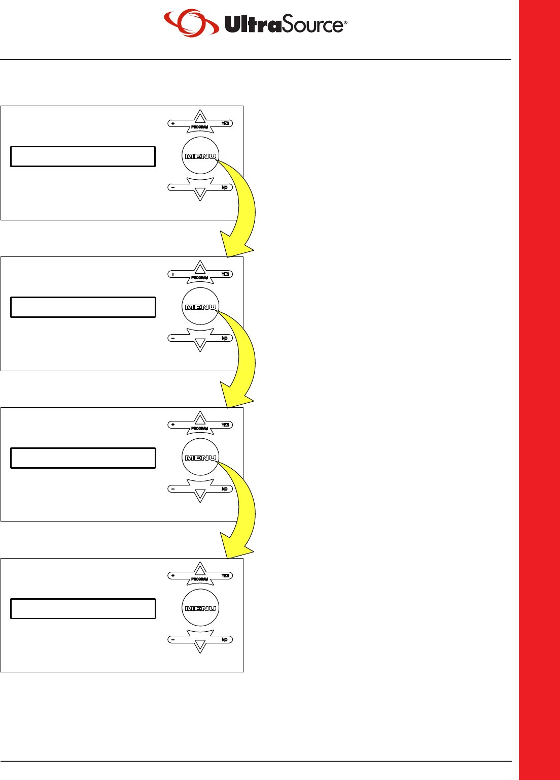
Figure 3.5
VACPLUS: 4.0
SEAL: 1.2
VACUUM: 98
RUNNING PROG: 1
NO
-
+
PROGRAM
YES
-
NO
YES
PROGRAM
+
NO
-
YES
+
PROGRAM
YES
PROGRAM
+
-
NO
This is the Main Menu screen. When
the machine starts up, the last program
that was run will be the current program
shown in the window. To set the operating
parameters for the program shown press
the MENU Key.
VACUUM is set to % vacuum using the UP
and DOWN arrow keys. The range is 30%
to 99%.
Press the MENU Key.
VACPLUS may be set greater than zero
to allow the pump to continue evacuating
the chamber (for the specified number
of seconds) after the pressure in the
chamber has reached the % vacuum set
in the vacuum menu. The range is 0 to 20
seconds.
Press the MENU Key.
The SEAL setting is in seconds.
Use the UP and DOWN arrow keys to
change the seal time. The range is 0 to 2
seconds.
Press the MENU Key.

THE NEW STANDARD FOR INNOVATION • [email protected] • UltraSourceUSA.com
UltraSource LLC • 1414 West 29th Street • Kansas City, MO 64108-3604 USA • 800.777.5624 • 816.753.2150
3.4
OPERATION
Operator Menu on Digital Panel (continued)
WARNINGWARNING
Explosion hazard.
Do not use a gas with an oxygen content greater than 22% with gas flush option.
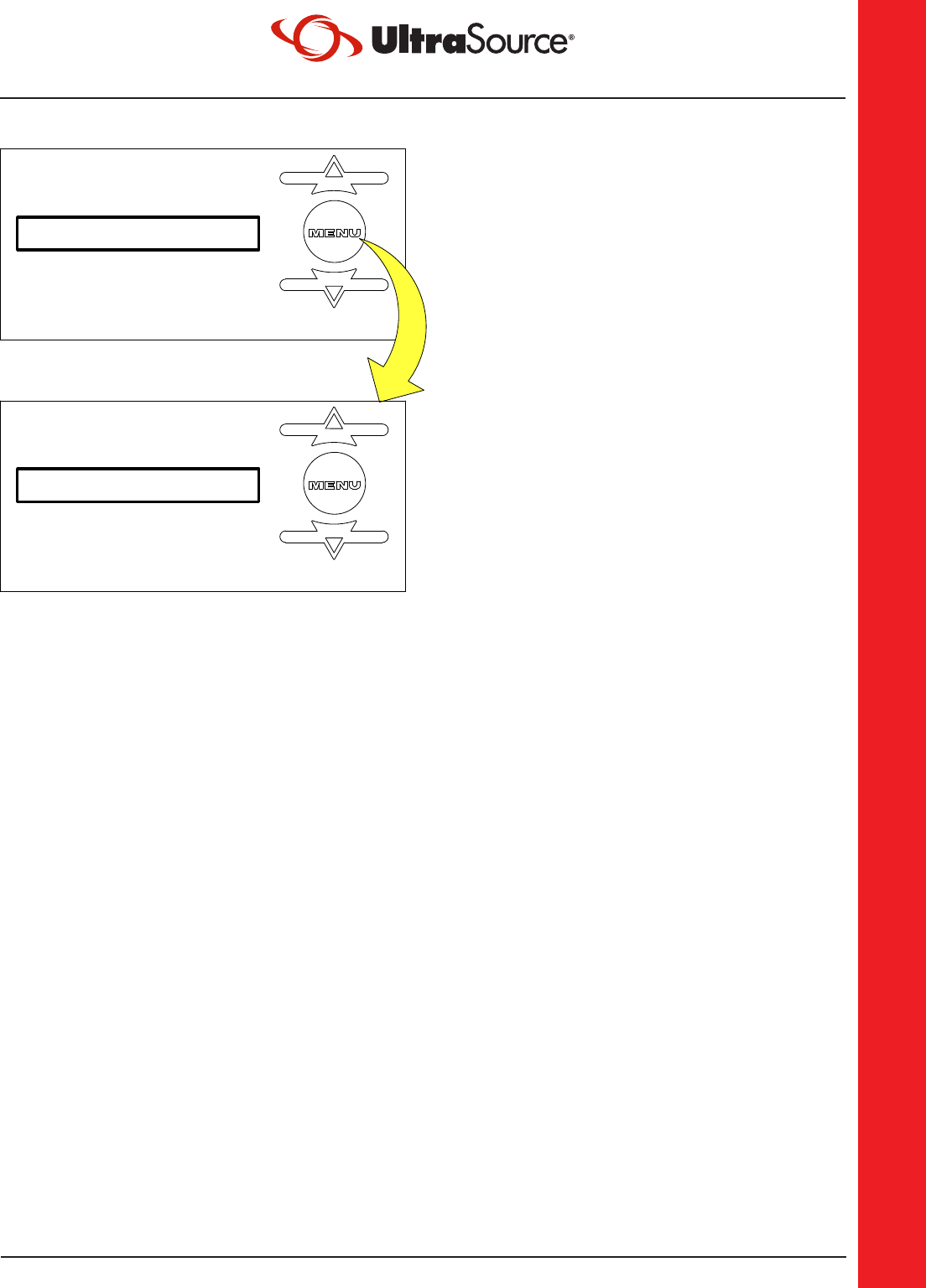
Figure 3.5
PRECUT: YES
GAS: 65
GAS: YES
NO
-
YES
+
PROGRAM
NO
-
YES
+
PROGRAM
NO
-
YES
+
PROGRAM
If the machine is equipped with the gas
option, it can be turned ON or OFF by
pressing the UP or DOWN arrow keys.
Press the MENU Key.
GAS is set to % gas using the UP and
DOWN arrow keys. This value also
corresponds to the vacuum reading inside
the chamber. It is recommended to use
Pulse Vent when gas flushing to a low %
vacuum. The range is 98% to 30%.
Press the MENU Key.
If the machine is equipped with the
PRECUT option, it can be turned ON or
OFF by pressing the UP or DOWN arrow
keys.
Press the MENU Key.
THE NEW STANDARD FOR INNOVATION • [email protected] • UltraSourceUSA.com
UltraSource LLC • 1414 West 29th Street • Kansas City, MO 64108-3604 USA • 800.777.5624 • 816.753.2150
3.5
OPERATION
Selecting a New Program
Figure 3.6
ENTER PROGAM: 2
RUNNING PROG: 1
+
-
PROGRAM
YES
NO
+
-
PROGRAM
YES
NO
From the Main Menu, use the UP and
DOWN arrow keys to select a new
program.
Press the UP arrow to switch to Program 2
(or any of the 10 programs).
New parameters may be set for Vacuum,
Seal Time, and Gas for Program 2
(following the procedures described in the
previous example) or simply close the lid
on the machine and run Program 2.

THE NEW STANDARD FOR INNOVATION • [email protected] • UltraSourceUSA.com
UltraSource LLC • 1414 West 29th Street • Kansas City, MO 64108-3604 USA • 800.777.5624 • 816.753.2150
3.6
OPERATION
Operation with Touch Screen
The touch screen control panel allows the user more options than the digital control panel.
The embedded microprocessor controls each sequence of the packaging operation. Settings
for the vacuum, gas, and sealing are entered as parameters through the keypad. This
allows the user to custom program every step of the packaging process. The precise vacuum
and gas pressures are controlled by a pressure based sensor. The vacuum pressure, gas
pressure, and seal time are displayed on a large 4.3” LCD touch screen, which can be read
easily in all lighting conditions. As each sequence is performed, the real-time pressure level
or cycle time is displayed.
The touch screen panel can save up to 99 pre-programmed routines, which can be retrieved
at any time for specific packaging applications. [With the supervisor security feature turned
on, these programs cannot be inadvertently changed.]
The VACPLUS option allows the operator to run the pump from .1 to 6 seconds after the set
vacuum level is achieved.
The Gas Flush option allows the operator to introduce an inert gas into the chamber after
the vacuum stage. This option can be used as a filler to prevent crushing of the product
after sealing, as a means to prolong shelf life or as a means to maintain desirable product
appearance.
The touch screen panel has an auto stop, which will automatically seal if the preset vacuum
is not reached. This feature decreases the cycle time and optimizes the vacuum level of each
product.
The touch screen panel meets or exceeds the requirements of NEMA 4. The front of the
touch screen is sealed and flush mounted for easy cleaning.
The touch screen has both pulsed vacuum and pulsed venting options for fragile product.
The touch screen has a maintenance screen for testing valves and a special loop option for
multiple vacuum/gas cycles before sealing.
Figure 3.4
THE NEW STANDARD FOR INNOVATION • [email protected] • UltraSourceUSA.com
UltraSource LLC • 1414 West 29th Street • Kansas City, MO 64108-3604 USA • 800.777.5624 • 816.753.2150
3.7
OPERATION
Operation with Touch Screen (continued)
NOTE: If the supervisor has set security on, program settings cannot be changed.
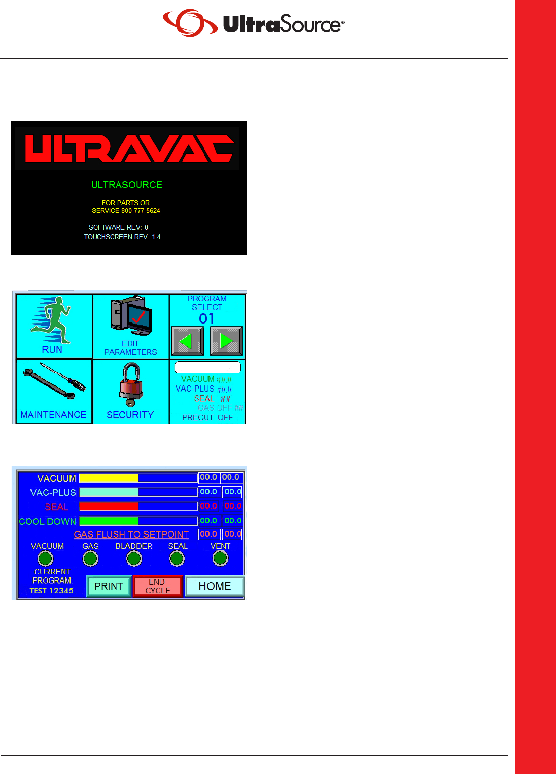
This is the splash screen. When the machine
starts up, this screen will display for a period
of time during bootup. Once the bootup
sequence has been completed, the screen
will automatically change to the Main Menu.
This is the Main Menu. This screen allows
access to all of the other functions of the
machine. A program can be selected
from this menu, and run from this menu.
Maintenance, Security, and Program
Parameters can also be edited from this
menu if the correct level of access is used.
This is the RUN Screen. This screen shows
the status of the program that is currently
being run, as well as the name of that
program.

THE NEW STANDARD FOR INNOVATION • [email protected] • UltraSourceUSA.com
UltraSource LLC • 1414 West 29th Street • Kansas City, MO 64108-3604 USA • 800.777.5624 • 816.753.2150
3.8
OPERATION
Operation with Touch Screen (continued)
NOTE: If the supervisor has set security on, program settings cannot be changed.
Some options may not apply to every machine.
This is the Edit Parameters screen. Every
program consists of multiple parameters.
These parameters are defined on the Edit
Parameters screen for each saved program.
VACUUM PERCENT:
This defines the percentage of vacuum to
achieve prior to sealing. The range is up to
99%.
VAC-PLUS:
This may be set from 0.1 to 6 seconds. A
setting greater than 0 allows the pump
to continue evacuating the chamber (for
the specified number of seconds) after the
pressure in the chamber has reached the %
vacuum set in the vacuum menu.
SEAL TIME:
The seal time setting is in seconds. The
range is 0 to 3 seconds.
PULSE VAC:
Pulse Vac allows for a more controlled
vacuuming process. Rather than simply
opening the vacuum valve for a continuous
vacuum, the valve is opened and closed
repeatedly until the chamber reaches the set
“Pulse Vac” vacuum level as defined in the
“Maintenance” screen.
PULSE VENT:
Pulse Vent allows for a more controlled
venting process. Rather than simply opening
up the valve for a continuous vent the
valve is opened and closed repeatedly
until the chamber vents back to the “Pulse
Vent” pressure setting as defined in the
“Maintenance” screen.

THE NEW STANDARD FOR INNOVATION • [email protected] • UltraSourceUSA.com
UltraSource LLC • 1414 West 29th Street • Kansas City, MO 64108-3604 USA • 800.777.5624 • 816.753.2150
3.9
OPERATION
Operation with Touch Screen (continued)
NOTE: If the supervisor has set security on, program settings cannot be changed.
Some options may not apply to every machine.
GAS OFF:
The Gas state button tells whether Gas
Flushing is turned on or off. Enable Gas by
turning this button to the ON position.
GAS %:
Gas is set to % gas by pressing the value
button on the touch screen and directly
editing the value using the provided
keypad. This value also corresponds to the
vacuum reading inside the chamber. It is
recommended to use pulse vent when gas
flushing to a low % vacuum. The range is
0.1% to 99%.
PRECUT OFF:
If equipped, This activates or deactivates the
Precut knife option

THE NEW STANDARD FOR INNOVATION • [email protected] • UltraSourceUSA.com
UltraSource LLC • 1414 West 29th Street • Kansas City, MO 64108-3604 USA • 800.777.5624 • 816.753.2150
3.10
OPERATION
Operation with Touch Screen (continued)
NOTE: If the supervisor has set security on, program settings cannot be changed.
Some options may not apply to every machine.
Program selection:
The Program Select feature has 99 different
user definable presets. To set a program
number, use the left and right arrows, or
press on the program select number to
bring up a keypad for number selection..
Once the program number you desire has
been selected, press on the White box to
pull up the keyboard screen, enter a name
for your program (up to 10 characters) and
press enter. You will be returned to the main
menu.
Press Edit Parameters. From the Edit
Parameters screen, enter the desired
settings for your product requirements.
When finished, press Exit. Your parameters
are now saved to the program number you
selected.

THE NEW STANDARD FOR INNOVATION • [email protected] • UltraSourceUSA.com
UltraSource LLC • 1414 West 29th Street • Kansas City, MO 64108-3604 USA • 800.777.5624 • 816.753.2150
3.11
OPERATION
Sealing with Air-Assist
All machines are equipped with regulators for air-assisted sealing. Set the air pressure
regulator to 20 p.s.i. increasing to a maximum of 40 p.s.i. While a good seal can be
obtained without air-assist, use air-assist when:
• Gas back-flushing above average pressure.
• Using shrink pouches.
• Packaging a product that easily contaminates the seal area of the pouch.
• Trying to overlap pouches.
• Wrinkles cannot be avoided in the seal area.
• Using the Double Seam Seal option.
• Always use air-assist when using the Perforating Knife Option.
• Always use air-assist when using the Precut Option.
• Always use air-assist when using the 10mm Wide Seal Band Option
Gas Flush Option
Gas flushing is the introduction of an inert gas into the chamber after the vacuum stage
is finished. Gas can be used as a filler to prevent crushing of the product after sealing, as
a means to prolong shelf life, or as a means to maintain desirable product appearance.
Commonly used gasses include nitrogen, carbon dioxide, or a mixture of both. Consult your
local gas supplier to select the proper gas for your product.
WARNINGWARNING
Explosion hazard.
Do not use a gas with an oxygen content greater than 22% with gas flush option.
Double Seam Seal Option
All machines are equipped with standard seal bars having a single seal element per
seal bar. The Double Seam seal bars have two seal elements per seal bar. We strongly
recommend using air-assisted sealing with this option to achieve best results.
10mm Wide Seam Seal Option
All machines are equipped with standard seal bars having a single seal element per
seal bar. The 10mm Wide Seam seal bars have a wide seal element. It is required to use
air-assisted sealing with this option to achieve best results.

THE NEW STANDARD FOR INNOVATION • [email protected] • UltraSourceUSA.com
UltraSource LLC • 1414 West 29th Street • Kansas City, MO 64108-3604 USA • 800.777.5624 • 816.753.2150
3.12
OPERATION
Perforating Knife Option
Perforating knives are used to facilitate the removal of excess pouch material. Perforating
knives are not intended to cut pouches off completely, only to perforate so that excess
material can be easily removed by hand.
Precut Option
The precut option is a patented system designed by UltraSource to increase the versatility
of the Ultravac
®
2100. This option increases the speed in which this machine can be loaded
with product. The user simply places the pouch full of product into the machine and pulls
it close to the seal bar allowing the excess material to hang on the outside of the machine.
Not only does this increase the loading speed, but it also improves the appearance of the
final product. The precut option also allows the end user to stock fewer sizes of pouches
because excess pouch material is trimmed away.
When using this option, the bag or pouch containing product is placed inside the machine
as usual. However, rather than having to carefully tuck the bag inside the slot in the
machine before closing the lid, the open end of the bag is placed outside the machine by
simply draping the bag over the side of the machine. When the lid is closed, the seal bar is
brought down and the special precut blade cuts evacuation slits in the bag or pouch, which
allow the air inside the bag to escape during the normal evacuation process.
Start by making sure the Precut menu is set to the “ON” position. With precut, air-assisted
sealing is required. Place the bag containing product inside the chamber. Drape the open
end of the bag over the side of the machine and close the lid. When the evacuation process
is finished, the bag will have “slits” pierced in it by the precut knife. The slits allow the air to
be evacuated from the bag. The slits also facilitate the removal of excess bag material after
the completion of the cycle.

THE NEW STANDARD FOR INNOVATION • [email protected] • UltraSourceUSA.com
UltraSource LLC • 1414 West 29th Street • Kansas City, MO 64108-3604 USA • 800.777.5624 • 816.753.2150
4.1
MAINTENANCE
MAINTENANCE
Prior to Cleaning
Every environment and application is different; therefore, UltraSource LLC cannot provide
cleaning instructions to guarantee microbiological sanitation. UltraSource requests that the
owner of this machine consult with sanitation experts to review the unit working in their
particular environment to develop a robust cleaning schedule and methodology, followed by
bacterial testing to ensure satisfactory cleaning procedures are followed.
Cleaning Recommendations
Before cleaning the machine, turn power off; disconnect the main power, and lockout the
connection.
DANGER
Hazardous voltage.
Disconnect and lockout power before servicing machine or cleaning. Do not remove panels
unless power has been disconnected and locked out at risk of electric shock hazard.
Check with the detergent and sanitizer manufacturers that their products are compatible
with the listed materials.
CAUTIONCAUTION
Cleaning agents.
Do not get the cleaning agents in eyes, on skin, or on clothing. Always wear rubber gloves,
goggles, and protective clothing when contact is likely. Consult product manufacturer for
specific details.
Never hose down the machine. Damage caused by hosing or high pressure washing is not
covered under warranty.
1. Filler Plates: Remove filler plates. The filler plates are made from polyethylene. Clean,
sanitize, and dry. High pressure water spray can be used on the filler plates.
2. Lid, Chamber, and Base: These components are made of aluminum. Clean the lid,
chamber, base, and silicone seal backup strip with a non-ionic cleaning solution such
as Crystal Simple Green.
3. Seal Bars: Remove the seal bars. The seal bars are made of phenolic. Clean, sanitize,
and dry. Also clean under the seal bar bladder in the lid, which is not removable.
4. Clean under the machine.
5. Reinstall the seal bars.
6. Use bacteriological testing to insure cleaning process.
WARNINGWARNING
Electrical Supply Cord.
The supply cord must be replaced by an Ultravac Services Service Technician or similarly
qualified person in order to avoid hazard.

THE NEW STANDARD FOR INNOVATION • [email protected] • UltraSourceUSA.com
UltraSource LLC • 1414 West 29th Street • Kansas City, MO 64108-3604 USA • 800.777.5624 • 816.753.2150
4.2
MAINTENANCE
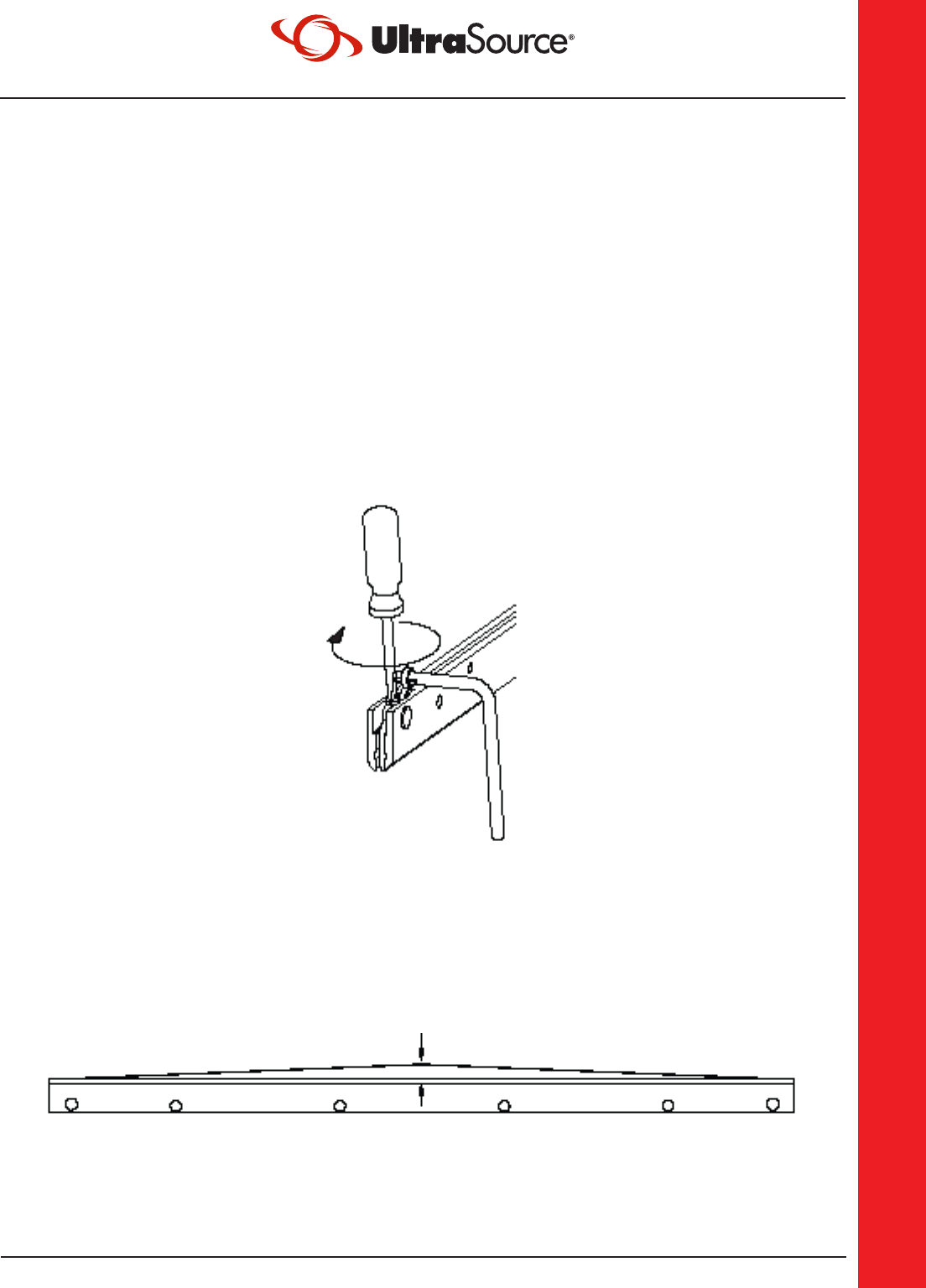
Step 1.
Remove the seal bars from the machine. Pull
off the Teflon
®
tape strip and discard. Clean
off any remaining Teflon
®
tape adhesive
using acetone or an equivalent solvent.
Step 2.
Using a 2mm Allen wrench, loosen the set
screws for the cut-off wire and the seal
element on both ends of the seal bar and
discard.
Step 3.
If you are replacing the L-shaped spring retainer and the spring at this time, loosen the set
screw and remove the old spring retainer and spring and install the new ones. Adjust the
spring retainer to allow a 1/8-in. gap between the spring retainer and the seal bar. This will
allow the seal element to remain under tension after tightening the seal element.
Vacuum Pump Maintenance
Consult the pump manufacturer’s manual provided with the machine for detailed
information.
Seal Bar Maintenance
The following illustrations show replacement of the seal elements for the seal bars.
Figure 4.1
Figure 4.2
Figure 4.3
Teflon
®
tape
Clamping
Screw
Spring
Retainer
Brass
Contact
Tightening
Tool
Seal
Element
Spring
Retainer
1/8-in.
Set
Screw
THE NEW STANDARD FOR INNOVATION • [email protected] • UltraSourceUSA.com
UltraSource LLC • 1414 West 29th Street • Kansas City, MO 64108-3604 USA • 800.777.5624 • 816.753.2150
4.3
MAINTENANCE
Seal Bar Maintenance (continued)
Step 4.
Insert the new seal element through the hole in the brass contact. Leave about 3/4-in.
of excess seal element extending past the brass contact and tighten the clamping screw.
Insert the other end of the element through brass contact on the opposite end of the seal
bar. Place a slotted tip screwdriver on top of the seal element and against the brass contact
where the seal element exits. Using the tightening tool provided (or needle nose pliers),
tighten the seal element as shown.
Step 5.
While maintaining tension on the tightening tool, use the slotted tip screwdriver to tighten
the clamping screw.
NOTE: A 1.5mm Allen wrench will be needed to tighten the clamping screws on a Double
Seam seal bar.
Step 6.
Check the tension of the seal element by pulling it up at the middle of the bar. The seal
element should not pull beyond 3/16-in. of the seal bar. If there is not enough tension,
tighten as necessary. Elements may break in the middle of the bar if tension is not set
properly. Install the new Teflon
®
tape strip over the bar.
3/16-in. maximum
Figure 4.4
Figure 4.5

THE NEW STANDARD FOR INNOVATION • [email protected] • UltraSourceUSA.com
UltraSource LLC • 1414 West 29th Street • Kansas City, MO 64108-3604 USA • 800.777.5624 • 816.753.2150
4.4
MAINTENANCE
Reading the Indicators
All machines are controlled by an analog control module (with knobs) or a digital control
module (with touch pad) designed to aid in troubleshooting. The analog control module,
mounted behind the front control panel, has five red indicator lights (LEDs) mounted to it.
To view the indicator lights on the analog control module during operation remove the six
screws on the front of the control panel and pull the control panel out. The digital panel
has indicator lights mounted on the front below the ON/OFF switch. The indicator lights
correspond to the operating devices and should turn on and off in the following sequence
when the machine lid is closed:
1. Vacuum Valve [SOL-1]
2. Gas Flush Valve [SOL-2] (Optional)
3. Seal Bladder Valve [SOL-3]
(Stays on until completion of cycle)
4. Seal Impulse Contractor [C-2]
5. Ventilation Valve [SOL-4]
The device should be operating when the LED is illuminated. If the LEDs illuminate in the
proper sequence, but there is still a problem, look for the problem in the operating device
itself. If the LEDs do not sequence properly, look for a problem in the related potentiometer
or the control module.
1. VACUUM VALVE [SOL-1]
2. GAS FLUSH VALVE [SOL-2] (OPTIONAL)
3. SEAL BLADDER VALVE [SOL-3]
(STAYS ON UNTIL COMPLETION OF CYCLE)
4. SEAL IMPULSE CONTACTOR [C-2]
5. VANTILATION VALVE [SOL-4]

THE NEW STANDARD FOR INNOVATION • [email protected] • UltraSourceUSA.com
UltraSource LLC • 1414 West 29th Street • Kansas City, MO 64108-3604 USA • 800.777.5624 • 816.753.2150
4.5
MAINTENANCE
Troubleshooting
Problem Indications Remedy
Machine will not start Green power “ON” light not
lit when switch is turned on
Make sure that the power
requirements match those given
on the nameplate. Also, check
fuse F-3; replace if blown.
Vacuum pump does not run Make sure that the power
requirements match those given
on the nameplate. Also, check the
overload OL-1; reset if necessary.
No vacuum When lid is closed, indicator
light (VAC) is “OFF” on the
control module
Check lid switches LS-1 and LS-2
for proper adjustment
Vacuum not pulling lid down
on both sides
Check intake screen in vacuum
pump hose barb for blockage,
pieces of bags, labels, bone, etc.
Longer vacuum cycle times Check intake screen in vacuum
pump hose barb for blockage
No gas flush (optional) If indicator light (GAS) is lit Check for proper gas pressure
going into gas inlet
If indicator light (GAS) is not
lit
Check for proper operation of gas
flush valve (SOL-2)
possible defective control module
Gas flushes to one chamber
side only
Check gas flush selector valve
(V-1) for proper adjust
Chamber not venting
(lid will not open)
Lid will not open and red
indicator light “VENT” on
control module is lit
Check ventilation valve SOL-4 for
proper operation
“VENT” indicator light is not
lit
possible defective control module
NOTE: Lid can be released by pulling the hose off of
the vacuum gauge to remove product.

THE NEW STANDARD FOR INNOVATION • [email protected] • UltraSourceUSA.com
UltraSource LLC • 1414 West 29th Street • Kansas City, MO 64108-3604 USA • 800.777.5624 • 816.753.2150
4.6
MAINTENANCE
Troubleshooting
Problem Indications Remedy
Improper or no
sealing
Bladder light on control
module is lit but the seal bar
does not come down
Check to make sure that the
regulator knob is turned fully
clockwise, or, if air-assist is used,
set to the recommended pressure
Check seal bladder valve SOL-3
for proper operation
The seal bar is not heating
up even though the red
seal light on the front panel
comes on
Check seal bar connection points
and clips for corrosion and proper
tension
The red seal light on the
front panel either does not
light for the proper length
of time (1/2 to 1 second) or
does not light at all
Check for broken seal element
Check seal bar fuse F-1 for front
seal bar and F-2 for rear seal bar*
Make sure the seal impulse
potentiometer POT-3 is set high
enough or check for defective
control module
Front or rear seal bar
heating, but not both
Check seal bar fuse F-1 for front
seal bar and F-2 for rear seal bar*
* Fuses F-1 and F-2 only apply to machines shipped before 1/1/2006.
NOTE: For proper sealing, three things must occur:
1. The seal bar must come down and place adequate pressure between the seal bar and
the backup strip.
2. The seal element must heat up sufficiently to fuse the pouch.
3. The pouch must be allowed to cool for a time to ensure a good “set.”

THE NEW STANDARD FOR INNOVATION • [email protected] • UltraSourceUSA.com
UltraSource LLC • 1414 West 29th Street • Kansas City, MO 64108-3604 USA • 800.777.5624 • 816.753.2150
4.7
MAINTENANCE
Supervisor Menu on Digital Panel
Untrained personnel should not alter any setting in the supervisor menu.
Figure 4.6
WAITTIME: 4
CUTTIME: 1.5
PREVAC: 25
RUNNING PROG: 1
NO
YES
PROGRAM
NO
YES
PROGRAM
NO
YES
PROGRAM
NO
YES
PROGRAM
-
+
-
+
-
+
-
+
This is the main menu screen. When
the machine starts up, the last program
that was run will be the current program
shown in the window.
Press and hold down both arrow keys for
at least 3 seconds to enter the supervisor
menu.
NOTE: If your machine is not installed
with the precut option, disregard the
PREVAC, CUTTIME, and WAITTIME
parameters.
PREVAC is the % vacuum that you wish to
reach before activating the knife, which
makes slits in the bag for precut. Use the
up or down arrow keys to change the
current setting.
The range is from 5% to 20% vacuum.
Press the MENU key.
CUTTIME is the number of seconds that
the seal valve is activated. This is the
time when the knife actually makes the
evacuation slits in the bag/pouch for
precut. The range is from 0 to 3 seconds.
Press the MENU key.
WAITTIME is the number of seconds the
machine waits for the knife to retract
before resuming the vacuum cycle. The
range is from 0 to 6 seconds.
Press the MENU key.
The following are parameters that can
only be set in the supervisor menu.

THE NEW STANDARD FOR INNOVATION • [email protected] • UltraSourceUSA.com
UltraSource LLC • 1414 West 29th Street • Kansas City, MO 64108-3604 USA • 800.777.5624 • 816.753.2150
4.8
MAINTENANCE
Supervisor Menu on Digital Panel
Figure 4.7
# PROGRAMS: 10
SECURITY: NO
COOLDOWN: 4.0
TEST: YES
NO
YES
PROGRAM
NO
YES
PROGRAM
NO
YES
PROGRAM
NO
YES
PROGRAM
-
+
-
+
-
+
-
+
COOLDOWN is the time that the machine
waits after sealing the bag/pouch before
the seal bars retract. This allows time for
the actual seal to cool down and take a set.
The range is from 1 to 8 seconds.
Press the MENU key.
SECURITY can be turned on by selecting
yes. If security is on, the operator menu will
be read only and the operator will not be
able to change any settings.
Press the MENU key.
This is how you specify the maximum
number of programs that may be saved in
memory. Each program may have its own
set of unique parameters.
This range is from 1 to 10.
Press the MENU key.
If TEST is set to YES (using the up arrow
key), the vacuum valve and vent valve may
be operated manually. The up arrow key
activates the vacuum valve, the down arrow
key activates the vent valve, and pressing
both at the same time turns them both off.
As you activate either valve, the vacuum
pressure is displayed.
Press the MENU key.

THE NEW STANDARD FOR INNOVATION • [email protected] • UltraSourceUSA.com
UltraSource LLC • 1414 West 29th Street • Kansas City, MO 64108-3604 USA • 800.777.5624 • 816.753.2150
4.9
MAINTENANCE
Supervisor Menu on Digital Panel
PULSE OFF: 1.0
PULSE ON: 1.2
PULSE TO: 50
PULSE VENT: YES
NO
YES
PROGRAM
NO
YES
PROGRAM
NO
YES
PROGRAM
NO
YES
PROGRAM
-
+
-
+
-
+
-
+
PULSE VAC allows for a more controlled
vacuum process. Rather than simply
opening up the vacuum valve for a
continuous vacuum, the vacuum valve is
opened and closed repeatedly until the
chamber reaches the desired vacuum.
Press the MENU Key.
This is the % vacuum reached by pulsing
the vac valve.
The range is 90% to 30%.
Press the MENU Key.
This is how long the vacuum valve is
turned on during the vacuum cycle.
The range is 0 to 3 seconds.
Press the MENU Key.
This is how long the vacuum valve is
turned off during the vacuum cycle.
The range is 0 to 3 seconds.
Press the MENU Key.
Figure 4.9
PULSE VAC

THE NEW STANDARD FOR INNOVATION • [email protected] • UltraSourceUSA.com
UltraSource LLC • 1414 West 29th Street • Kansas City, MO 64108-3604 USA • 800.777.5624 • 816.753.2150
4.10
MAINTENANCE
Supervisor Menu on Digital Panel
Figure 4.8
PULSE OFF: 1.0
PULSE ON: 1.2
PULSE TO: 50
PULSE VENT: YES
NO
YES
PROGRAM
NO
YES
PROGRAM
NO
YES
PROGRAM
NO
YES
PROGRAM
-
+
-
+
-
+
-
+
PULSE VENT allows for a more controlled
venting process. Rather than simply
opening up the vent valve for a continuous
vent, the vent valve is opened and closed
repeatedly until the chamber vents back to
atmospheric pressure.
Press the MENU Key.
This is the % vacuum reached by pulsing
the vent valve before the vent valve opens
completely to fully vent the chamber.
The range is 90% to 30%.
Press the MENU Key.
This is how long the vent valve is turned on
during the vent cycle.
The range is 0 to 3 seconds.
Press the MENU Key.
This is how long the vent valve is turned
off during the vent cycle.
The range is 0 to 3 seconds.
Press the MENU Key.

THE NEW STANDARD FOR INNOVATION • [email protected] • UltraSourceUSA.com
UltraSource LLC • 1414 West 29th Street • Kansas City, MO 64108-3604 USA • 800.777.5624 • 816.753.2150
4.11
MAINTENANCE
EXIT GAS: YES
LOOP #: 1
NO
YES
PROGRAM
NO
YES
PROGRAM
-
+
-
+
VAC TIMEOUT: ON
NO
YES
PROGRAM
-
+
If the machine is equipped with the LOOP
option, this is the number of vacuum/gas
cycles the control will perform prior to the
seal and vent.
The range is 1 to 5 cycles.
The default value is 1 cycle.
Press the MENU Key.
If the Loop # is set greater than 1, the
control can be set to exit this loop on either
the last gas cycle or the last vacuum cycle
prior to sealing.
The DOWN arrow key indicates NO.
The UP arrow key indicates YES.
Press the MENU Key.
VAC TIMEOUT is an option that is turned
ON or OFF. If set OFF, default, the machine
will time out if the preset vacuum is not
reached in 6 seconds, and the machine
will complete the cycle. If set ON and the
machine does not reach the preset vacuum
in thirty seconds, then the panel will display
VAC ERROR and vent the chamber without
sealing.
Supervisor Menu on Digital Panel
Figure 4.10

THE NEW STANDARD FOR INNOVATION • [email protected] • UltraSourceUSA.com
UltraSource LLC • 1414 West 29th Street • Kansas City, MO 64108-3604 USA • 800.777.5624 • 816.753.2150
4.12
MAINTENANCE
Supervisor Menu with Touch Screen
NOTE: If the supervisor has set security on, program settings cannot be changed.
This is the Main Menu. This screen allows
access to all of the other functions of
the machine. The supervisory menu can
be accessed by entering the required
maintenance password in Security, and then
pressing the Maintenance button.
Default Maintenance Password is listed in
the security setup section of this manual.
This is the primary Maintenance menu.
This allows access to all of the various
supervisory and maintenance related
screens.
Global Parameters consist of machine
specific global parameters such as Vacuum
Time Out limits, Cool Down times, and
Language Selection.
Security Setup allows the default passwords
to be changed, and allows the supervisor to
restrict the editing of program parameters
to Maintenance level supervisors or to allow
anyone using the machine to make these
changes.
Pulse Vac-Vent Setup allows the supervisor
to configure the behavior of the Pulse Vac
and Pulse Vent operations if being used.
Configuration is a factory configuration
menu that allows the touch screen to
be properly configured for operation on
a specifically equipped machine. These
settings should NEVER be changed in
the field unless instructed to do so by an
Ultravac Services technician.
Precut Options: If the machine is equipped
with the PRECUT option, selecting this icon
allows the parameters to be set. See precut
and looping options for details
THE NEW STANDARD FOR INNOVATION • [email protected] • UltraSourceUSA.com
UltraSource LLC • 1414 West 29th Street • Kansas City, MO 64108-3604 USA • 800.777.5624 • 816.753.2150
4.13
MAINTENANCE
Supervisor Menu with Touch Screen (continued)
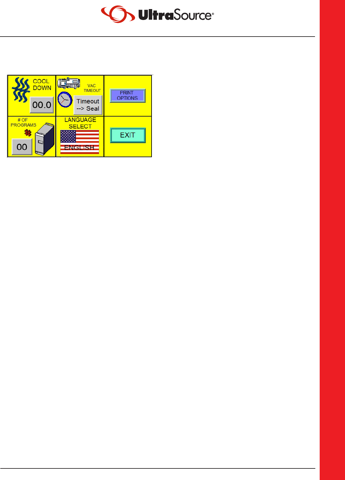
Global Parameters
Cool Down: This parameter determines how
long the cool down period is in each cycle.
This can be set by pressing the value button
and changing the value using the provided
keypad. The range for this value is 0 to 10.
Vac Timeout: The Vacuum Timeout
parameter determines how the machine
behaves if the Vacuum Timeout is reached
before the cycle completes.
Timeout --> Seal: This will cause the
machine to seal the package
immediately if a Vacuum Timeout
fault occurs.
Timeout --> Vent: This will cause the
machine to stop the vacuum process,
vent the chamber and leave the
package unsealed.
Print Options: This is used to enable/disable
the printer function.
# of Programs: This parameter defines the
number of programs that can be stored. The
range for this value is 1 to 99.
Language Select: This allows the user to
select a different operating language for
the touch screen. The machine is equipped
with four base languages including English,
French, German and Spanish. The language
can be selected simply by pressing the flag
like button and cycling through the options.
Press Exit when done and this will save your
changes.

THE NEW STANDARD FOR INNOVATION • [email protected] • UltraSourceUSA.com
UltraSource LLC • 1414 West 29th Street • Kansas City, MO 64108-3604 USA • 800.777.5624 • 816.753.2150
4.14
MAINTENANCE
Following the selection of Print Options in
Global parameters, this screen will appear.
Enabling or disabling the printer feature is
done by selecting the Print ON/OFF but-
ton.
The Company name field contains up to
12 characters. This field may be used for
any text, such as Lot Number, for any given
product run. Enter desired text, press and
hold Save name until you hear two beeps..
The default time is set to CST (GMT-6:00).
You will need a pencil eraser to perform
this operation. Press the arrow key in the
lower RH corner and the Icon group will
appear to the left. Press the Gear Icon and
the virtual keypad will appear. Press the
number 1 six times, and press enter. The
System settings screen will appear, and
you will be in the network settings tab,
which does not apply to these machines.
Please note the time is formatted as a 24
hour clock!!! Select the Time/Date tab at
the top of the system settings screen, and
using your eraser adjust the time and date.
When finished, press apply, and press OK.
The time and date have now been saved.
The remaining tabs SHOULD NOT be
used! Changes to these features should
only be performed or under direction of a
trained Ultravac Services technician!!
Supervisor Menu with Touch Screen (continued)
Print Options
111111

THE NEW STANDARD FOR INNOVATION • [email protected] • UltraSourceUSA.com
UltraSource LLC • 1414 West 29th Street • Kansas City, MO 64108-3604 USA • 800.777.5624 • 816.753.2150
4.15
MAINTENANCE
Supervisor Menu with Touch Screen (continued)
Security Setup
The security setup screen allows the
maintenance supervisor to enable a certain
level of security and to change the default
passwords assigned to the machine.
The default passwords are as follows:
Level One: 456
Level Two: 789
Turning Security On in this menu will
restrict the editing of program parameters
to those with a value Level One password.
The Maintenance menu will always remain
secured by the Level Two password.
If Security is set to Security Off (as shown
in the corresponding image to the left),
running program parameters will be
editable by anyone.
Changing the default passwords can be
done by setting the new password in this
screen. Keep in mind that these passwords
are NOT recoverable should they be
forgotten.

THE NEW STANDARD FOR INNOVATION • [email protected] • UltraSourceUSA.com
UltraSource LLC • 1414 West 29th Street • Kansas City, MO 64108-3604 USA • 800.777.5624 • 816.753.2150
4.16
MAINTENANCE
Supervisor Menu with Touch Screen (continued)
Pulse Vac and Pulse Vent Setup
Pulse Vac and Pulse Vent Setup allows the
maintenance supervisor to configure the
appropriate Pulse Vac and Vent limits.
Pulse Vac On Time:
This value determines how long each pulse
is fired during a Pulse Vac operation.
Pulse Vac Off Time:
This value determines how long each pulse
is in the off position during a Pulse Vac
operation.
Pulse Vac to Percent:
This value determines the final desired
vacuum percentage to be reached during a
Pulse Vac operation.
Pulse Vent On Time:
This value determines how long each pulse
is fired during a Pulse Vent operation.
Pulse Vent Off Time:
This value determines how long each pulse
is in the off position during a Pulse Vent
operation.
Pulse Vent to Percent:
This value determines the final desired
vacuum percentage to be reached during a
Pulse Vent operation.

THE NEW STANDARD FOR INNOVATION • [email protected] • UltraSourceUSA.com
UltraSource LLC • 1414 West 29th Street • Kansas City, MO 64108-3604 USA • 800.777.5624 • 816.753.2150
4.17
MAINTENANCE
Supervisor Menu with Touch Screen (continued)
Precut and Looping options
Prevac - 0-99% of vacuum before slits
are cut in the bag. Default 25%
Cut time - Amount of time allotted for
the cut cycle, 0.1 - 9 seconds Default 1.5
seconds
Wait time - Amount of time from Cut
cycle finish to Vacuum cycle startup
0.1 - 9 seconds, Default 4 seconds.
If the machine is equipped with the loop
option, this is the number of vacuum/
gas cycles the control will perform prior
to the seal and vent. The range is 1 to 5
cycles. The default is 1.
If the loop # is set to greater than 1,
the control can be set to exit the loop
on either the last gas cycle or the last
vacuum cycle prior to sealing.

THE NEW STANDARD FOR INNOVATION • [email protected] • UltraSourceUSA.com
UltraSource LLC • 1414 West 29th Street • Kansas City, MO 64108-3604 USA • 800.777.5624 • 816.753.2150
4.18
MAINTENANCE
Changing Vacuum Pump Oil and Filter
NOTE: The pump should have been running for at least 15 minutes to warm the pump oil.
1. Turn the power switch to the “OFF” position and disconnect the power.
DANGER
Hot oil.
Hot oil poses scalding risk. Take necessary precautions while draining warm oil.
DANGER
Hazardous voltage.
Disconnect and lockout power before servicing machine or cleaning. Do not remove panels
unless power has been disconnected and locked out at risk of electric shock hazard.
2. Position an oil collection pan underneath the Oil Drain Plug.
3. Loosen and remove the Oil Fill Plug with a 1¼-in. open end wrench.
4. Loosen the Oil Drain Plug located to the front and lower middle on the pump with a
1¼-in. open end wrench. Remove the plug slowly to control the flow of oil.
5. Replace auto-type oil filter with a filter wrench (strap wrench.) Coat face of gasket on
new filter with oil and hand tighten until gasket contacts base, then tighten two-thirds
turn more. DO NOT OVER TIGHTEN.
6. With the oil drained, replace the Oil Drain Plug and wipe any excess oil off of the pump.
7. Fill the pump with oil until the level is at the maximum lines on the Oil Sight Glass.
Replace the Oil Filler Cap.
8. Reconnect the power cord back into the wall receptacle.
9. Cycle the machine a couple of times, unplug, and check the Oil Level. Add oil to the
maximum line. DO NOT OVER FILL.

THE NEW STANDARD FOR INNOVATION • [email protected] • UltraSourceUSA.com
UltraSource LLC • 1414 West 29th Street • Kansas City, MO 64108-3604 USA • 800.777.5624 • 816.753.2150
4.19
MAINTENANCE
Maintenance Log
A maintenance log is a journal of all maintenance performed. Each entry includes a
date, maintenance performed (details about the type of work done), and technician (who
performed the maintenance). The maintenance log is also a place where a schedule is kept
for further maintenance.
A maintenance log will clearly show oil changes, daily inspections, Teflon
®
tape
replacement, and so on. A master copy has been provided on page 4.20, please create a
copy and store in the back of this owner’s manual.
Service Log
A service log is a journal of all service work performed. Each entry includes a date, service
provided (details about the type of service), and technician (who performed the service).
A service log will clearly show training provided, frequent wear items, and so on. A master
copy has been provided on page 4.21, please create a copy and store in the back of this
owner’s manual.

THE NEW STANDARD FOR INNOVATION • [email protected] • UltraSourceUSA.com
UltraSource LLC • 1414 West 29th Street • Kansas City, MO 64108-3604 USA • 800.777.5624 • 816.753.2150
4.20
MAINTENANCE
Maintenance Log
Date Maintenance Performed Technician
THE NEW STANDARD FOR INNOVATION • [email protected] • UltraSourceUSA.com
UltraSource LLC • 1414 West 29th Street • Kansas City, MO 64108-3604 USA • 800.777.5624 • 816.753.2150
4.21
MAINTENANCE
Service Log
Date Service Provided Technician

THE NEW STANDARD FOR INNOVATION • [email protected] • UltraSourceUSA.com
UltraSource LLC • 1414 West 29th Street • Kansas City, MO 64108-3604 USA • 800.777.5624 • 816.753.2150
4.22
MAINTENANCE
THIS PAGE LEFT BLANK INTENTIONALLY.

THE NEW STANDARD FOR INNOVATION • [email protected] • UltraSourceUSA.com
UltraSource LLC • 1414 West 29th Street • Kansas City, MO 64108-3604 USA • 800.777.5624 • 816.753.2150
5.1
SCHEMATICS
SCHEMATICS
Designation and Function of Controls
The following designations are found on the Electrical Diagrams:
Manually Activated Switches and Buttons:
SW-1 On/off control power
SW-3 On/off gas flush
SW-4 Quick seal (Optional)
Limit Switches:
LS -1 Left chamber cycle start
LS-2 Right chamber cycle start
Contactors:
C-1 Vacuum pump
C-2 Seal impulse
C-3 Redundant seal impluse
Overloads and Fusing:
OL-1 Vacuum pump motor
F-3 Control power fuse
Control Modules:
MCM Master control module
R-1 Redundant seal impluse
contactor timer
Control Lights:
LT-1 On/off control power
light (green)
LT-2 Seal impulse on light
(red)
Transformers:
T-1 Seal impulse, front
T-2 Seal impulse, rear
T-3 Control power
Motors:
M-1 Vacuum pump
Solenoid Valves:
SOL-1 Vacuum flush solenoid
SOL-2 Gas flush solenoid
SOL-3 Seal bladder solenoid
SOL-4 Ventilation solenoid
Mechanically Activated Switches
(Pneumatic Diagram only):
V-1 Gas selector valve

STARTUP
UltraSource LLC • 1414 West 29th Street • Kansas City, MO 64108-3604 USA • 800.777.5624 • 816.753.2150
5.2
SCHEMATICS
230 Volt, Single Phase, Digital Panel

STARTUP
UltraSource LLC • 1414 West 29th Street • Kansas City, MO 64108-3604 USA • 800.777.5624 • 816.753.2150
5.3
SCHEMATICS
230 Volt, 3 Phase, Digital Panel

STARTUP
UltraSource LLC • 1414 West 29th Street • Kansas City, MO 64108-3604 USA • 800.777.5624 • 816.753.2150
5.4
SCHEMATICS
380 Volt, 50 Hz, Digital Panel

STARTUP
UltraSource LLC • 1414 West 29th Street • Kansas City, MO 64108-3604 USA • 800.777.5624 • 816.753.2150
5.5
SCHEMATICS
380 Volt, 50 Hz, W/O Neutral Digital Panel

STARTUP
UltraSource LLC • 1414 West 29th Street • Kansas City, MO 64108-3604 USA • 800.777.5624 • 816.753.2150
5.6
SCHEMATICS
460 Volt, 3 Phase, Digital Panel

STARTUP
UltraSource LLC • 1414 West 29th Street • Kansas City, MO 64108-3604 USA • 800.777.5624 • 816.753.2150
5.7
SCHEMATICS
575 Volt, 3 Phase, Digital Panel

STARTUP
UltraSource LLC • 1414 West 29th Street • Kansas City, MO 64108-3604 USA • 800.777.5624 • 816.753.2150
5.8
SCHEMATICS
Pneumatic Diagram
UltraSource LLC • 1414 West 29th Street • Kansas City, MO 64108-3604 USA • 800.777.5624 • 816.753.2150
THE NEW STANDARD FOR INNOVATION • [email protected] • UltraSourceUSA.com
6.1
PARTS
PARTS
Recommended Spare Parts
Qty.
UltraSource
Part No.
Description
1 ea 8610 01 Seal Bar Assembly
10 ft 880431 Back Up Strip
4 ea 880443 Back Up Strip Textured
12 ft 880432 Lid Gasket
1 ea 88 0746 Seal Element
3 ft 885507 Teflon
®
Tape
1 ea 860908 DIN Coil
1 ea 860906 Vacuum Valve Diaphragm
1 ea 860907 Vent Valve Diaphragm
2 gal Specify pump Vacuum Pump Oil
1 ea Specify pump Vacuum Pump Oil Filter
1 ea 861002 Bladder Assembly
Select your machine’s configuration:
1 ea 860250 Double Seam Seal Bar Contact Kit
1 ea 863016 10mm Wide Seal Bar Contact Kit
1 ea 861013 Single Seam Seal Bar Contact Kit
For Analog Control Panel:
5 ea 860337 Fuse for Control Power, 1A
1 ea 860313 Potentiometer, Evac/Gas
1 ea 860314 Potentiometer, Sealing
1 ea 860327 Relay Module
For specific system replacement parts,
Contact a parts representative for further assistance:
Phone (816) 753-2150 • Fax (816) 561-2854
Toll-Free (800) 777-5624
THE NEW STANDARD FOR INNOVATION • [email protected] • UltraSourceUSA.com
UltraSource LLC • 1414 West 29th Street • Kansas City, MO 64108-3604 USA • 800.777.5624 • 816.753.2150
6.2
PARTS
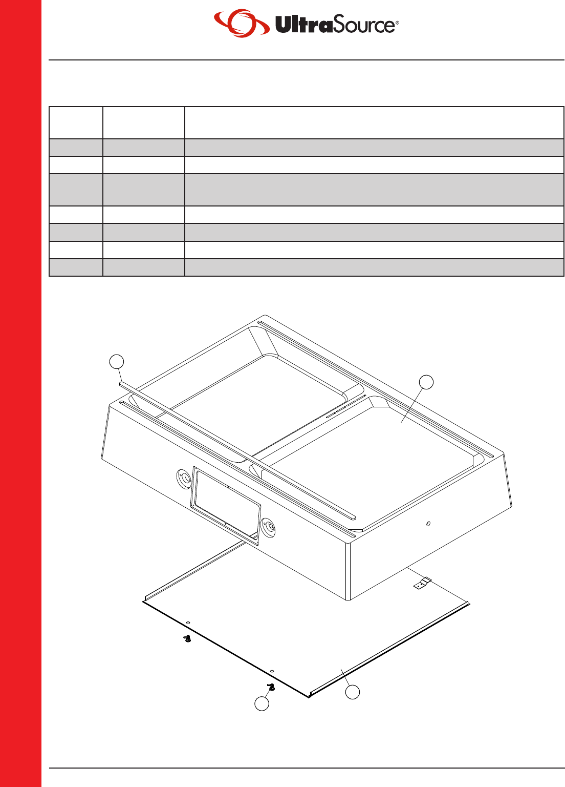
Miscellaneous Machine Parts
Parts List and Diagram
Item
No.
UltraSource
Part No.
Description
1 860402 Filler Plate Set (two sets per machine)
3 880431 Chamber Gasket (10-ft. required)
860950
Chamber Gasket, Grey (10-ft. required)
(for precut and perforating knife options)
880443 Chamber Gasket - 4 pcs. - Textured
4 860844 Cover Panel with Latches
5 860409 Latch
861228 Coiled Lanyard (between chassis and cover)
3
4
5
1
UltraSource LLC • 1414 West 29th Street • Kansas City, MO 64108-3604 USA • 800.777.5624 • 816.753.2150
THE NEW STANDARD FOR INNOVATION • [email protected] • UltraSourceUSA.com
6.3
PARTS
Lid, External
Parts List
Item No. Part No. Description
860200 Lid casting, 8-in. (Lid Assy available, Call our Parts Dept.)
860201 Lid casting, 12-in. (Lid Assy available, Call our Parts Dept.)
1 880432 Lid Gasket (12-ft. required)
2 860954 Hose, 1/4-in. Reinforced (35-in. required)
3 860110 Hose Clamp for 1/4-in. Reinforced Hose
4 860109 Brass Hose Barb
5 863031 Wire Harness, Complete
6 860009 Cord Grip, 1/2”NPT, .375”-.500”
7 8 6 0113 Lid Handle
8 860269 Nut, M10 Nylon Lock
1
2
3
4
6
5
8
7
THE NEW STANDARD FOR INNOVATION • [email protected] • UltraSourceUSA.com
UltraSource LLC • 1414 West 29th Street • Kansas City, MO 64108-3604 USA • 800.777.5624 • 816.753.2150
6.4
PARTS
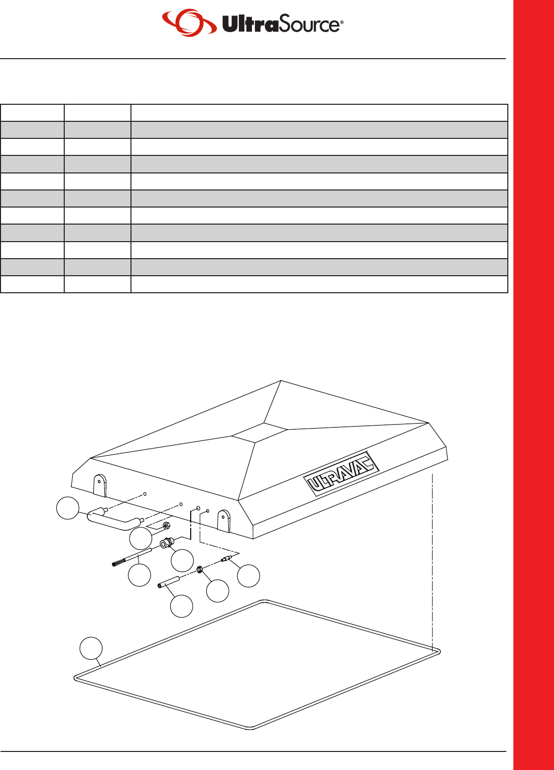
Lid, Internal
Parts List
Item
No.
UltraSource
Part No.
Description
1 861071 10mm Wide Seal Bar Complete (refer to page 6.9)
903037-10 10mm Wide Seal Bar with Knife (one complete assembly)
861001 Single Seam Seal Bar Complete (refer to page 6.11)
860001 Single Seam Seal Bar with Knife (one complete assembly)
2 860102 Seal Bar Support
3 860226 Seal Bar Support Washer
4 860254 Screw, M5x25 Slotted Flat Head
5 860261 Nut, 5mm Nylon Lock
6 860258 Screw, M5x8 SHCS
7 860257 Screw, M5x20 Slotted Pan Head
8 860005 Electrical Contact
9 866832 Screw, M5x35 SHCS
10 860260 Washer, 5mm Lock
11 866764 Nut, 5mm Hex
12 860954 1/4-in. Hose (specify length)
13 860107 1/4-in. Hose “T”
14 860110 Hose Clamp
15 860307 Bladder Return Spring
16 860030 Bladder Backup Plate
17 8610 02 Bladder Assembly
18 861232 Swing Arm
19 860202 Swing Arm Tie Block
Kit to add on knife blade (903055) includes:
3 860226 Seal Bar Support Washer
4 860254 Screw, M5x25 Slotted Flat Head
5 860261 Nut, 5mm Nylon Lock
6 860258 Screw, M5x8 SHCS
7 860257 Screw, M5x20 Slotted Pan Head
11 866764 Nut, 5mm Hex
20 860018 Knife Only
21 860991 Pre-cut Shim

UltraSource LLC • 1414 West 29th Street • Kansas City, MO 64108-3604 USA • 800.777.5624 • 816.753.2150
THE NEW STANDARD FOR INNOVATION • [email protected] • UltraSourceUSA.com
6.5
PARTS
Lid, Internal
Diagram
WITH PERFORATION KNIFE
421
5
3
6
1
7
20
17
19
5
11
8
13
9
18
15
16
10
10
6
14
12
2

THE NEW STANDARD FOR INNOVATION • [email protected] • UltraSourceUSA.com
UltraSource LLC • 1414 West 29th Street • Kansas City, MO 64108-3604 USA • 800.777.5624 • 816.753.2150
6.6
PARTS
Legs and Pump
Parts List
Item
No.
UltraSource
Part No.
Description
1 860705 Leg
2 860767 Pump Plate Brace
3 900039 Pump, 5-hp for 230V, 1-phase
900165 Pump, 7-½-hp for 230/380/460V, 3-phase
900166 Pump, 7-½-hp for 575V, 3-phase
900253 Pump, 10-hp for 200V, 3-phase
900255 Pump, 10-hp for 230/380/460V, 3-phase
900257 Pump, 10-hp for 575V, 3-phase
900305-200 Pump, 12-hp for 200V, 3-phase
900305-230 Pump, 12-hp for 230/380/460V, 3-phase
900305-575 Pump, 12-hp for 575V, 3-phase
4 860613 Hose Barb, 2-in.
5 860759 Pump Mounting Plate
6 810109 Bolt, M10x25 Hex Head
7 860268 Washer, 10mm Flat
8 860269 Nut, 10mm Lock
9 86116 4 Bolt, 3/4-10 Thread x 3-3/4-in., Hex Head
10 860733 Nut, 3/4-in. Jam
11 860730 Leg Spacer
12 860732 Washer, 3/4-in. Flat
13 860714 Nut, 3/4-in. Acorn
14 860736 Washer, 3/4-in. Lock
15 863080 Kit, Support Pads with M10x35 SHCS
16 903010 Kit, Caster (optional)

UltraSource LLC • 1414 West 29th Street • Kansas City, MO 64108-3604 USA • 800.777.5624 • 816.753.2150
THE NEW STANDARD FOR INNOVATION • [email protected] • UltraSourceUSA.com
6.7
PARTS
Legs and Pump
Diagram
1
2
3
4
5
6
7
8
9
9
10
11
13
12
13
16
15
14
12

THE NEW STANDARD FOR INNOVATION • [email protected] • UltraSourceUSA.com
UltraSource LLC • 1414 West 29th Street • Kansas City, MO 64108-3604 USA • 800.777.5624 • 816.753.2150
6.8
PARTS
Double Seam Seal Bar
Parts List and Diagram
Item
No.
Description
863017 Double Seam Seal Bar Complete
1 880746 Seal Element
2 885507 Teflon
®
Tape, (3-ft. required per seal bar) (not shown)
3 860250 Double Seam Seal Contact Kit
Kit (860250) includes:
Element Spring
Element Clip
Double Seam Contact
Screw, M3x12 Slotted Flat Head
Set screw, M4x6 Socket
3
1
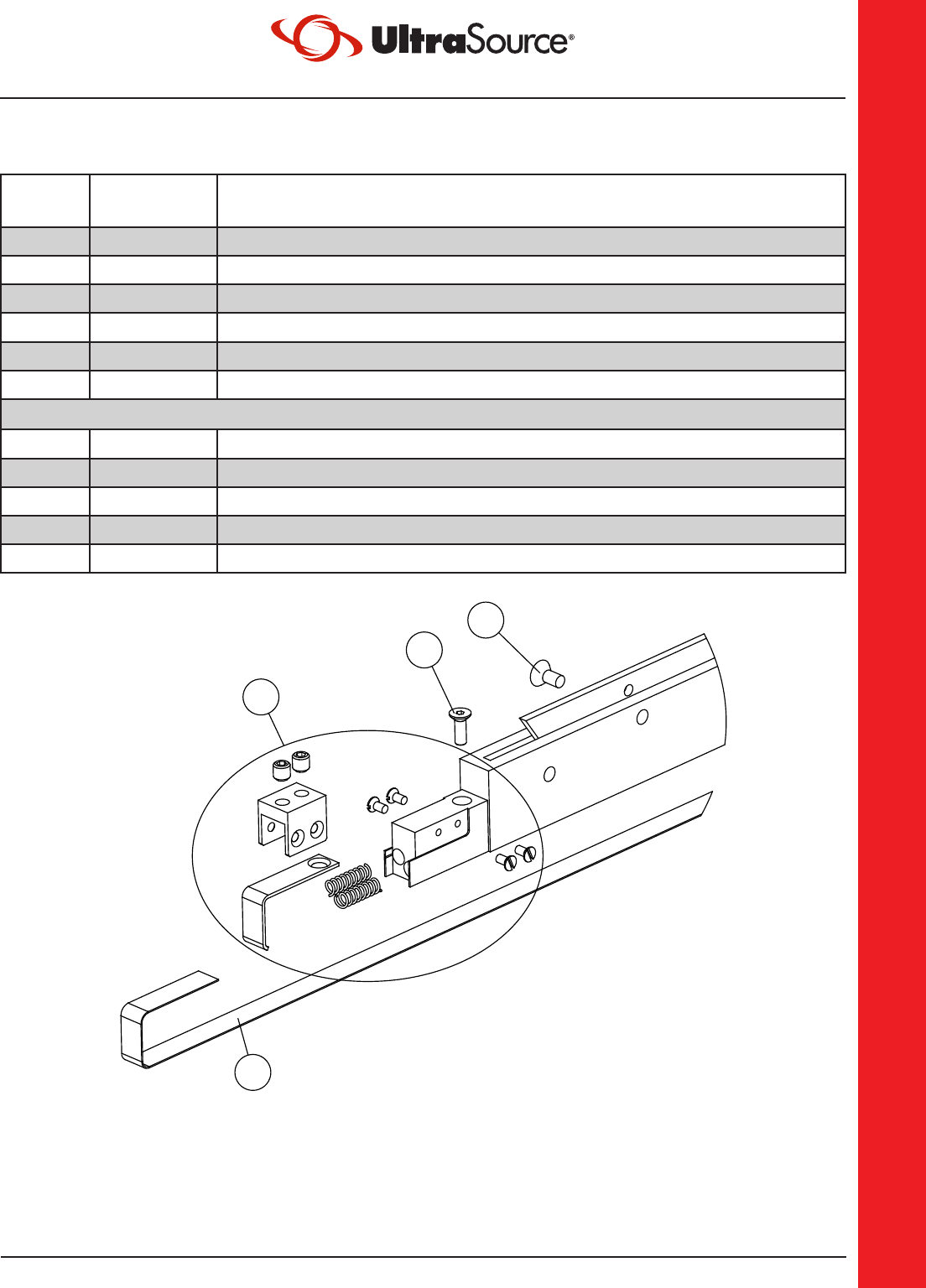
UltraSource LLC • 1414 West 29th Street • Kansas City, MO 64108-3604 USA • 800.777.5624 • 816.753.2150
THE NEW STANDARD FOR INNOVATION • [email protected] • UltraSourceUSA.com
6.9
PARTS
10mm Wide Seal Bar
Parts List and Diagram
Item
No.
Description
861071 10mm Wide Seal Bar Complete
1 860512 Seal Element
2 885507 Teflon
®
Tape, (3-ft. required per seal bar) (not shown)
3 860174 Screw, M4x12 Slotted Flat Head
4 860251 Screw, M5x10 Slotted Flat Head
5 863016 10mm Wide Seal Contact Kit
Kit (863016) includes:
Element Spring
Element Clip
10mm Wide Seam Contact
Set Screw, M5x6 Socket Head
Screw, M3x6 Slotted Flat Head
4
1
3
5

THE NEW STANDARD FOR INNOVATION • [email protected] • UltraSourceUSA.com
UltraSource LLC • 1414 West 29th Street • Kansas City, MO 64108-3604 USA • 800.777.5624 • 816.753.2150
6.10
PARTS
Single Seam Seal Bar
Parts List and Diagram
Item
No.
Description
861001 Single Seam Seal Bar Complete
1 8 80746 Seal Element
2 885507 Teflon
®
Tape, (3-ft. required per seal bar) (not shown)
3 861013 Single Seam Seal Contact Kit
Kit (861013) includes:
Element Spring
Element Clip
Single Seam Contact
Screw, M3x5 Slotted Panhead
Set Screw, M3x5 Socket
1
3

UltraSource LLC • 1414 West 29th Street • Kansas City, MO 64108-3604 USA • 800.777.5624 • 816.753.2150
THE NEW STANDARD FOR INNOVATION • [email protected] • UltraSourceUSA.com
6.11
PARTS
Vacuum Manifold
Parts List and Diagram
Item
No.
Description
1 861152 Manifold Assembly
Assembly (861152) includes:
Valve Manifold Plate
Valve, Mebner Vacuum and Vent
Fitting, 2-in. Close Nipple
Fitting, 2-in. Hose Barb
NOTE: New manifold o-ring (860603) recommended.
2 860618 Hose Clamp, 2-in.
3 860617 Vacuum Hose (to vacuum pump), (5-ft. required)
4 860603 Manifold O-Ring
5 860954 Braided Hose, 1/4-in.
6 861020 Electrical Switch Cable
7 860908 DIN Coil, [SOL-1] [SOL-4]
8 860906 Replacement Vacuum Valve Diaphragm (not shown)
9 860907 Replacement Vent Valve Diaphragm (not shown)
5
7
6
2
3
6
5
1
4
NOTE: Epoxy is applied to fittings at
valve inlets for vacuum integrity.

THE NEW STANDARD FOR INNOVATION • [email protected] • UltraSourceUSA.com
UltraSource LLC • 1414 West 29th Street • Kansas City, MO 64108-3604 USA • 800.777.5624 • 816.753.2150
6.12
PARTS
Main Electrical Components
Parts List
Item
No.
Description
1 8 6 0 311 Transformer, Control, 50VA, 460, 230/115 VAC
860394 Transformer, Control, 50VA, 208/115 VAC
809207 Transformer, 50VA, 380/400/415V-110/230V
2 860255 Screw, M5x6 Slotted Pan Head
3 860312 Transformer, Seal, 300KVA, 460, 230, 208/115 VAC
860059 Transformer, Seal, 600VA, 460/230, 48 VAC (double seam seal)
861286 Transformer, 380/400/415 24/48 350VA
861289 Transformer, 380V, 48V, 600VA
864106 Transformer, 480V 1500KV (Wideband seal only)
4 860703 Relay, Interval 4 sec. for Sealing
5 860793 Contactor, Sealing
6 860341 Terminal, End Cap
7 861179 Contactor, Pump, 32A, 600V, 110 Volt Coil
8 860339 Fuse Holder, Control
860337 Fuse, 1A (not shown)
9 860340 Terminal Block
10 860342 Terminal, Ground Block
11 See Overload Table below
Pump
Size
Voltage
Overload
Part No.
Pump
Size
Voltage
Overload
Part No.
7 ½ HP
208V
860795
230V
380V
861214460V
575V
10 HP
208V
860796
230V
380V 860797
460V 861214
575V 860797
5 HP 230V 1 PH 860796 12 HP
208V
860835
230V
380V
860797460V
575V

UltraSource LLC • 1414 West 29th Street • Kansas City, MO 64108-3604 USA • 800.777.5624 • 816.753.2150
THE NEW STANDARD FOR INNOVATION • [email protected] • UltraSourceUSA.com
6.13
PARTS
Main Electrical Components
Diagram
6
10
9
8
5
2
4
5
11
7
3
3
1

THE NEW STANDARD FOR INNOVATION • [email protected] • UltraSourceUSA.com
UltraSource LLC • 1414 West 29th Street • Kansas City, MO 64108-3604 USA • 800.777.5624 • 816.753.2150
6.14
PARTS
Base
Parts List
Item
No.
UltraSource
Part No.
Description
1 863012 Wire Harness, Complete
2 860954 1/4-in. Reinforced Hose (34-in. required)
3 861018 Cycle Switch Assembly Complete with Harness
860309 Cycle Switch [LS-1] [LS-2]
4 861020 Harness for Valve, Complete with DIN Plug
5 861023 Valve Assembly, Seal Pilot with Fittings [SOL-3]
Valve Assembly (861023) includes:
Valve, 3-Way, NC, 1/4 NPT Ports, 120 Volt
Hose Barb, 1/4-in. - 1/4-in. Elbow
Hose Barb, 1/4-in. - 1/8-in. Elbow
6 860404 Brass Fitting
7 860775 Air Pressure Regulator and Gauge Assembly
8 860514 Hose Barb, 1/4-in. - 1/4-in. Elbow
9 861178 Electrical Compression Fitting, 230/460 Volt
861131 Electrical Compression Fitting, 380 Volt
10 861045
Pump Harness, 208/230/460V, 5- and 7-½-hp
Pump Harness, 460V, 10- and 12-hp
861046 Pump Harness, 380V, 5-, 7-½-, 10-, and 12-hp
861288 Pump Harness, 380V w/o Neutral (Special Option)
861176 Pump Harness, 208/230V, 10- and 12-hp
11 861035 Power Harness, 208/230V, 5- and 7-½-hp
861035-0 01 Power Harness, 230V,SINGLE PHASE 5-hp
861036 Power Harness, 380V, 5-, 7-½-, 10-, and 12-hp
861287 Power Harness, 380V w/o Neutral (Special Option)
861037 Power Harness, 460V, 5-, 7-½-, 10-, and 12-hp

UltraSource LLC • 1414 West 29th Street • Kansas City, MO 64108-3604 USA • 800.777.5624 • 816.753.2150
THE NEW STANDARD FOR INNOVATION • [email protected] • UltraSourceUSA.com
6.15
PARTS
10
9
9
6
8
7
4
3
3
1
2
11
5
Base
Diagram

THE NEW STANDARD FOR INNOVATION • [email protected] • UltraSourceUSA.com
UltraSource LLC • 1414 West 29th Street • Kansas City, MO 64108-3604 USA • 800.777.5624 • 816.753.2150
6.16
PARTS
Gas Flush
Parts List
Item
No.
Description
1 860352 Electrical Switch Cable
2 861024 Valve Assembly, Gas Pilot with Fitting
Valve Assembly (861024) includes:
Two-way Pilot Valve for Gas [SOL-2]
Hose Barb, 1/4-in. - 1/4-in. Elbow
3 860404 Brass Fitting
4 860513 Gas Inlet Barb, 1/4-in.
5 860514 Hose Barb, 1/4-in. - 1/4-in. Elbow
6 861025 Valve Assembly, Gas Switching with Plate
Valve Assembly (861025) includes:
Gas Flush Selector Valve [V-1] (Serial #2090-Current)
Hose Barb, 1/4-in. - 1/4-in. Elbow
Valve Plate
Nut, 6mm Nylon Lock
Screw, M6x40 SHCS
861010 Assembly, Gas Flush Hose [Items 7, 8, 9]
NOTE: Shown is 1/2 of the gas flush hose assembly (861010). One assembly required per
chamber side.
7 860954 Reinforced Hose, 1/4-in. (specify length)
8 860107 Hose Barb, ‘T’, 1/4-in.
9 860507 Gas Nozzle
10 863024 Bag Holder with Foam Padding (in machine lid)
860203 Replacement Foam Padding Only

UltraSource LLC • 1414 West 29th Street • Kansas City, MO 64108-3604 USA • 800.777.5624 • 816.753.2150
THE NEW STANDARD FOR INNOVATION • [email protected] • UltraSourceUSA.com
6.17
PARTS
2
1
3
4
6
7
8
9
10
5
5
Gas Flush
Diagram
861344
861345
835514
9
THESE
NOZZLES
APPLY TO
SERIAL
NUMBERS
6108 AND
6046 ONLY

THE NEW STANDARD FOR INNOVATION • [email protected] • UltraSourceUSA.com
UltraSource LLC • 1414 West 29th Street • Kansas City, MO 64108-3604 USA • 800.777.5624 • 816.753.2150
6.18
PARTS
Swing Arm Assembly
Parts List
Item
No.
Description
861158 Lid Lever Shaft and Cam with Dowel Assembly [Items 1, 2, 3, 4]
1 861155 Lid Lever Shaft
2 860403 Connecting Shaft
3 861156 Dowel, M10x25mm long, Stainless Steel (Serial #4606 - Current)
4 8 61157 Cam Lever Complete Assembly
Assembly (861157) includes:
Cam Lever
Cam Bushing
Screw, M8x30 Socket Head
5 866766 Nut, M8
6 860424 Spring Retainer
7 866742 Screw, M10x35 Socket Head
8 860244 Lid Spring
9 861008 Bearing Hub Assembly
Assembly (861008) includes:
Bearing Retainer
Shaft Bearing
Bearing Hub
10 866739 Screw, M8x25 Socket Head
11 86 0114 Lid Lever
86 0111 Lid Lever for Utilities Clamp (backside of machine)
12 860749 Utilities Clamp
13 860754 Button, Cable Clamp
14 866729 Screw, M5x20 Socket Head
15 860414 Bushing Spacer
16 860401
Lid Lever Bushing

UltraSource LLC • 1414 West 29th Street • Kansas City, MO 64108-3604 USA • 800.777.5624 • 816.753.2150
THE NEW STANDARD FOR INNOVATION • [email protected] • UltraSourceUSA.com
6.19
PARTS
1
2
5
8
6
7
4
3
15
14
12
11
7
10
9
16
7
13
Swing Arm Assembly
Diagram

THE NEW STANDARD FOR INNOVATION • [email protected] • UltraSourceUSA.com
UltraSource LLC • 1414 West 29th Street • Kansas City, MO 64108-3604 USA • 800.777.5624 • 816.753.2150
6.20
PARTS
Digital Control Panel
Parts List and Diagram
Item
No.
UltraSource
Part No.
Description
1 860995 Front Panel Assembly
2 860673 Vacuum Sensor
3 860316 Main Power On/Off Switch [SW-1]
4 860683 Fitting 1/4 x 1/8 Reducer
5 866728 Screw, M5x16 SHCS, SS
6 866773 Washer, M5 Flat
NOTE: Torque specification for 866728 (item 5) is 20 inch-pound.

UltraSource LLC • 1414 West 29th Street • Kansas City, MO 64108-3604 USA • 800.777.5624 • 816.753.2150
THE NEW STANDARD FOR INNOVATION • [email protected] • UltraSourceUSA.com
6.21
PARTS
3
9
11
11
5
1
2
3
5
11
2
1
4
3
6
9
7
8
Touchscreen Control Panel 861300
ITEM PART NUMBER DESCRIPTION QTY
1 861301 BEZEL, TOUCHSCREEN PANEL 1
2 861302 DECAL, TOUCHSCREEN 1
3 861304 PWB TOUCHSCREEN HMI5043N 1
4 866783 WASHER, M4, SPLIT LOCK, SS 1
5 861382 T.S. HMI5043LB, PROG’D, ZPL 1
6 869628 SCREW, 8-23 X 3/8-IN. 1
7 861324 STANDOFF, 8-32 X 1 1
8 861320 SCREW, M4 X 40 PAN HEAD 6
9 861325 SPACER, NYLON, 5/16” X 1 1/4” 6
10 861306 DECAL, CORELOK, F/TOUCH SCREEN (N/A) 1
11 860316 SWITCH, POWER ON/OFF & BODY ASSY 1

THE NEW STANDARD FOR INNOVATION • [email protected] • UltraSourceUSA.com
UltraSource LLC • 1414 West 29th Street • Kansas City, MO 64108-3604 USA • 800.777.5624 • 816.753.2150
6.22
PARTS
3
1
2
3
Filter Inlet
Pump Inlet
Direction
of Flow
Inline Filter
Parts List and Diagram
Item
No.
UltraSource
Part No.
Description
861153 Inline Filter Complete
1 835427 Tube, Inlet Filter
2 884250 Filter Screen
3 835429 Gasket, Inlet Filter
Hardware included in complete assembly (861153):
Screw, M8x120 Hex Head
Nut, 8mm Hex
Nut, 8mm Wing
NOTE: Epoxy is applied to fittings at filter and pump inlets for vacuum integrity.

UltraSource LLC • 1414 West 29th Street • Kansas City, MO 64108-3604 USA • 800.777.5624 • 816.753.2150
THE NEW STANDARD FOR INNOVATION • [email protected] • UltraSourceUSA.com
7.1
REFERENCE
REFERENCE MANUALS
R5 Series Vacuum Pumps
Included within Ultravac
®
2100 owner’s manual is an installation and operating manual for
the vacuum pump equipped with this vacuum chamber machine.
Refer to page 6.1 of the Ultravac
®
2100 owner’s manual for oil and replacement filter part
numbers for this machine.
For Replacement Parts, Call:
Phone (816) 753-2150 • Fax (816) 561-2854
Toll-Free (800) 777-5624

INSTALLATION
AND
OPERATING MANUAL
R5 Series
Current Models 0025, 0040, 0063, 0100 and 0250
Single Stage Rotary Vane Vacuum Pumps

TABLE OF CONTENTS
GENERAL
Identification
Operating Principles
1.0 INSTALLATION
1.1 Unpacking
1.2 Location
1.3 Power Requirements
1.4 Vacuum Connections
1.5 Oil Filling
2.0 OPERATION
2.1 Start-up
2.2 Gas Ballast
2.3 Stopping Pump
2.4 Water-Cooled Pumps
2.5 Oxygen Service Pumps
3.0 MAINTENANCE
3.1 Pump Oil
3.1.1 Oil Level
3.1.2 Oil Type and Quantity
3.1.3 Oil and Filter Change
3.2 Automotive-Type Oil Filter
3.3 Exhaust Filter (Ref. 120)
3.4 Vacuum Inlet Filter
3.5 Maintenance Chart
3.6 Overhaul Kit/Filter
4.0 TROUBLESHOOTING
5.0 STANDARD LIMITED WARRANTY
TECHNICAL DATA
MOTOR AND ELECTRICAL DATA
We reserve the right to change the product at any time without any form of notification. The information in this publication is accu-
rate to the best of our ability at the time of printing. Busch, Inc. will not be responsible for errors encountered when attempting to
perform tasks outlined in this publication.
1

GENERAL
Identification
For model identification, see the nameplate
mounted on the side of the exhaust box.
This manual is written to cover RA and RC ver-
sions of models 0025, 0040, 0063, 0100, and 0250
with a "C" or "E" appearing as the seventh character
in the model type number stamped into the name-
plate. For example it would appear as follows:
RAXXXX - C
XXX - XXXX
When ordering parts, it is helpful to include the
identification code stamped into the side of the
cylinder as well as the serial number from the name-
plate.
Operating Principles
All reference (Ref. XX) numbers listed in the
text and on illustrations throughout this manual are
related to the drawings and parts list near the center
of this publication.
All R5 Series, Single Stage, Rotary Vacuum
Pumps are direct-driven, air-cooled, oil-sealed
rotary vane pumps which operate as positive dis-
placement pumps. As Figure 1 shows, they consist
of a rotor mounted concentrically on the drive shaft
and positioned eccentrically in a cylindrical stator.
The rotor has three radially sliding vanes which
divide the pump chamber into three segments. The
gas to be pumped enters at the inlet port (Ref. 260),
passes through the inlet screen (Ref. 261) and the
open anti-suck-back valve (Ref. 251) into the pump
chamber. As the rotor rotates, the inlet aperture is
closed, the gas is compressed and forced out through
one-way valves between the pump cylinder and the
exhaust box. This operation is repeated three times
each revolution.
1.0 INSTALLATION
1.1 Unpacking
Inspect the box and pump carefully for any signs
of damage incurred in transit. Since all pumps are
ordinarily shipped FOB our factory, such damage is
the normal responsibility of the carrier and should be
reported to them.
Remove the nuts from the bottom of the
box/crate and pull the pump out of the container,
then unscrew the studs from the bottom of the rub-
ber feet.
2
All R5 series pumps are designed to handle air.
Vapor in the air stream can be tolerated when the
pump is operated within certain operating parame-
ters as defined by Busch, Inc. Engineering (see
Section 2.2 Gas Ballast). When you desire to use
the pump on an air stream that contains vapors, con-
tact Busch, Inc. Engineering for operating recom-
mendations; otherwise, the warranty could be void.
Figure 1 Module Cross Section

The inlet port of the pump is covered with a plas-
tic cap prior to shipment to prevent dirt and other
foreign material from entering the pump. Do not
remove this cover until the pump is actually ready
for connection to your system.
1.2 Location
The pump must be installed in a horizontal posi-
tion on a level surface so that the pump is evenly
supported on its rubber feet. Allow at least one foot
(five feet for large pumps) of air space between the
pump and any walls or other obstructions to the flow
of cooling air.
Also, adequate ventilation must be provided for
the fans on the pump and motor (i.e., do not locate
the pump in a stagnant air location).
Whenever the pump is transported, be sure to
drain the oil prior to shipping to avoid vane break-
age when restarting the pump.
Do not tip the pump over if it is filled with oil.
Locate the pump for easy access to the oil sight
glass (Ref. 83) in order to inspect and control the oil
level properly. Allow clearance at the exhaust flange
area to provide service access to the exhaust filters.
1.3 Power Requirements
The schematic diagram for the electrical connec-
tion is located in the junction box or on the name-
plate of the pump motor.
The motor must be connected according to the
electrical codes governing the installation. The
power supply must be routed through a fused switch
to protect the motor against electrical or mechanical
overloads. The motor starter has to be set consistent
with the motor current listed on the motor name-
plate.
If the pump is supplied with a manual motor
starter, it is preset at the factory in accordance with
the customer’s specification. For other voltage
requirements, contact the factory for motor and/or
starter information.
NOTE: See the motor manufacturer’s manual
for start-up maintenance of the motor.
Correct direction of rotation is marked by an
arrow on the motor fan housing and is counterclock-
wise when looking at the motor from the motor's fan
side.
1.4 Vacuum Connections
Use a line size to the vacuum system that is at
least as large as that of the pump inlet. Smaller lines
will result in lower pumping speeds than the rated
values.
Install a drip leg and drain on the vertical pipe
near the pump inlet. Drain the drip leg often to pre-
vent condensation from entering the pump.
If more than one vacuum pump or a receiver
tank is connected to a common main line, each
pump should have its own manual or automatic
operated shut-off valve or positive action check
valve. The built-in anti-suck-back valve should not
be used as a shut-off valve for the vacuum system.
Remove the plastic protective cap from the inlet
port prior to connection of the pump to the system.
The following threads are provided at the inlet of
the R5 Series pumps:
Pump Size Size Threads
0025/0040 1 1/4" Female NPT
0063/0100 1 1/4" Female NPT
0250 2" Female NPT
Caution: After the electrical connection has
been made, but before the pinup is filled with oil,
the rotation of the motor must be checked. Open
the inlet port and jog the motor briefly to make
sure rotation is correct. If it runs backwards and
if it is wired three phase power, reverse any two
leads of the three at the power connection.
3
Caution: The built-in anti-suck-back valve is
not positive action; do not use it as a system
check valve.

If the gas that is pumped contains dust or other
foreign solid particles, a suitable (10 micron rating
or less) inlet filter should be connected to the inlet
port. Consult the factory for recommendations.
1.5 Oil Filling
The pump is shipped without oil. After level
installation, and after correct rotation has been
established, fill the pump with the recommended
vacuum oil through the oil filling port (Ref. 88),
observing the "MAX" and "MIN" position at the oil
sight glass (Ref. 83).
Non-detergent oil should be used. Do not use
detergent motor oil as additives in detergent oil
will plug exhaust filter elements and shorten their
life.
It is recommended that Busch R500 Series oil be
used to receive the best performance from your vac-
uum equipment. R500 Series oil is a high quality
vacuum oil which will give longer running time
between oil changes, will provide better lubrication
at high operating temperatures, and will prolong the
life of exhaust filter elements. This oil can be
obtained directly from Busch, Inc. in Virginia
Beach, Virginia.
The strict use of Busch oils and parts from the
day of purchase can extend the standard warranty to
three years. Contact Busch, Inc. in Virginia Beach,
Virginia for details. Refer to page 20 for the standard
warranty.
For general applications, use R530 in most mod-
els. Use R590 or R570 in pumps that are operated
in high ambient temperatures (above 90°F) or high
operating pressure when the oil carbonizes (turns
black) before the change interval. Use R590 or R570
on 0250 pumps. Contact the factory for recommen-
dations when using other oils.
The following table gives the approximate quan-
tities of oil required for each pump:
Pump Type Oil Capacity (Qt.)
0025/0040 1.4
0063/0100 2.5/2.7
0250 7
The oil capacity chart should only be used as a
guide, since oil capacity may be slightly lower,
depending on whether the pump was filled previ-
ously, and whether all components such as oil filter,
oil lines, etc., were allowed to completely drain. Use
only the sight glass reading for proper level. Never
overfill.
For ambient operating temperatures lower than
41°F, use Busch R580 synthetic oil. If this does not
help (where the pump has difficulty starting due to
high oil viscosity) contact the factory in Virginia
Beach, Virginia.
Replace the oil fill plug (Ref. 88/90), making
sure that the gasket (Ref. 89) is in place and proper-
ly seated and secured. Some pumps are equipped
with an exhaust pressure gauge as an integral part of
the oil fill plug.
2.0 OPERATION
2.1 Start-up
Check rotation of the motor as described in para-
graph 1.3 - Power Requirements.
Fill the pump with oil as described in paragraph
1.5 - Oil Filling.
Start the pump and immediately close the inlet.
Run the pump for a few minutes before checking the
oil level again. With the pump shut off, the oil level
should be visible in the oil sight glass (Ref. 83),
between the "MIN" and "MAX" mark.
Add oil, if necessary, but only add it when the
pump has been shut off and the circulating oil has
Caution: When using PVC pipe or any static
enhancing material for the exhaust piping, make
provisions to safeguard against arcing from stat-
ic electricity. Arcing can ignite oil vapor that
may be present.
Warning: Keep the oil fill plug tight as pres-
sure in the exhaust box could cause bodily injury
if the plug is blown out. Do not fill/add the pump
with oil through the exhaust/inlet ports as there
is danger of breaking the vanes!
4

had sufficient time to return to the oil sump.
NOTE: The oil separated by the exhaust filter
element forms droplets on the outside of the exhaust
filter which collect at a low point in the upper half of
the exhaust box. From there the collected oil is
drained back to the oil sump via an oil check valve
(Pos 275) which opens on R5 RA Model Pumps
when the pump is shut off. It is necessary to shut off
the RA model pumps after every 8 hours of operation
to allow the check valve to open. If the pump is not
shut off after this time period, it is possible to starve
the pump of oil since the oil is not allowed to drain
back into the oil sump and/or oil droplets may be
blown out of the exhaust. If the pump is operating at
high pressure it may be necessary to shut it down
sooner than 8 hours.
On R5 (Standard) RC Model Pumps, the collect-
ed oil is drawn continuously during operation of the
vacuum pump to the inlet flange (Pos 260) via the
oil return line (Pos 290). The oil return line is con-
nected directly to the area of the exhaust box, down-
stream of the exhaust filter, which is at atmospheric
pressure. Therefore, a constant amount of air is
sucked into the pump which is an additional reason
that the R5 Standard Series Pumps do not achieve as
low a vacuum as the R5 Series Super Vacuum
Pumps.
2.2 Gas Ballast
All RA Series pumps are equipped with a gas
ballast valve. The gas ballast valve (Ref. 440) is
located between the inlet port and the exhaust box.
RA Series pumps up to size 100 are equipped with a
permanent gas ballast which cannot be shut off
unless the sintered filter is removed and the orifice
plugged. Larger pumps are equipped with an
adjustable gas ballast valve.
The adjustable gas ballast valve should normal-
ly be left open. Its primary function is to prevent
water vapor from condensing in the pump.
Condensation causes emulsification of the oil, loss
of lubricity, and possible rotor seizure.
2.3 Stopping Pump
To stop the pump, turn off the power. The pump
has a built-in anti-suck-back valve (Ref. 251 thru
255) to prevent the pump from rotating backwards
when it is shut off.
Install an automatic operated valve (such as a
check valve) in front of the pump, if more than one
pump is pumping on the same line or if there is a
sufficient volume of vacuum in the system to cause
the pump oil to be drawn into the piping when that
pump is shut down.
All R5 Series pumps are vented internally to
atmospheric pressure through venting holes which
are next to the exhaust valve assembly.
2.4 Water-Cooled Pumps
Water-cooled pumps are cooled by circulating
the oil through a shell-and-tube type heat exchanger.
The circulation of the pump oil through the shell is
created by vacuum in the pump, but the circulation
of the cooling water through the tubes is thermostat-
ically controlled. The flow rate of the cooling water
is controlled by a thermostatically activated valve
that senses, through a capillary bulb mounted in the
exhaust box, the pump's oil temperature as it is dis-
charged from the compression chamber. The valve
will open at its set point and close at approximately
3°F to 5°F below the set point. The valve set point is
adjustable as follows:
(a) Rotate the valve adjustment screw counter-
clockwise to cause the valve to open at a higher
temperature.
(b) Rotate the valve adjustment screw clockwise
to make the valve open at a lower temperature.
The thermostatic valve can be manually opened
by inserting a screwdriver under each side of the
spring guide and prying the spring and guide upward
away from the valve body.
Caution: Do not use the anti-suck-back valve
as a check or shut-off valve for your vacuum sys-
tem. Do not depend on the anti-suck-back valve
to prevent pump oil from migrating through the
inlet into the system when the pump is shut
down.
5

2.5 Oxygen Service Pumps
Application
If this pump is contaminated by organic com-
pounds do not attempt to use it on oxygen service
until it has been decontaminated.
These Installation and Operating Instructions are
valid for the following vacuum pumps:
RA/RC 0025 RA/RC 0100
RA/RC 0040 RA/RC 0250
RA/RC 0063
These pumps have been manufactured, solvent
washed (to remove organic contaminants) and
assembled according to the latest technical standards
and safety regulations. If this pump is not installed
properly or not used as directed, a dangerous situa-
tion or damage might occur.
It is mandatory that these operating instruc-
tions be read and understood prior to vacuum
pump installation and start-up.
Pump Overhaul/Repair
Busch Inc. strongly recommends that all major
repair operations be conducted at the factory.
Improper handling of repairs could result in
extreme danger to personnel operating the pump.
6
Warning: This pump is filled with a special
operating fluid. Do not use any other type of
fluid, oil and/or grease. Use one of the following:
• Fomblln LC 250
• Tyreno Fluid 12/25V (perfluorinated poly-
ether)
• KRYTOX ®Vacuum pump fluid by Du Pont
Company
If you have any questions, please phone our
Customer Service Department for more informa-
tion.
Figure 2 Typical Exhaust Box Cross Section

3.0 MAINTENANCE
R5 Series, Single Stage, Rotary Vacuum Pumps
require very little maintenance; however, to insure
optimum pump performance, the following steps are
recommended:
3.1 Pump Oil
3.1.1 Oil Level
With the pump installed relatively level, make
sure that there is sufficient clean oil in the pump.
The oil level should be observed on a daily basis
and/or after 8 hours of operation and should be
replenished if it drops below the 1/4 mark on the oil
sight glass. On R5 series pumps you must first shut
the pump off in order to let the oil flow back into the
oil sump prior to checking the sight glass. Allowing
insufficient time for the oil to drain back into the
sump on R5 series pumps prior to adding oil could
result in overfilling.
Oil level readings should be done only when the
pump is turned off. Oil can be added to the oil fill
port (Pos 88) if the pump is shut off and the circu-
lating oil has sufficient time to return to the oil
sump.
Under normal circumstances, it should not be
necessary to add or drain oil from the pump between
recommended oil changes.
A significant drop in oil level means there is an
oil leak or that an exhaust filter is broken, and the
pump should be smoking excessively. It is normal
for the oil to be foamy and light in color in an oper-
ating pump. However, if the oil is milky colored, it
is an indication that water is present in the oil.
Normally, by operating the pump for an extended
period, with the inlet suction blanked off and the gas
ballast (Pos 440) open on RA pumps, the water will
be purged from the oil. If the oil is dark colored, it
is contaminated or carbonized and must be changed.
3.1.2 Oil Type and Quantity
See Section 1.5 - Oil Filling - for details on oil
type and quantity.
3.1.3 Oil and Filter Change
Oil life is dependent upon the conditions to
which it is exposed. A clean, dry air stream and an
oil operating temperature under 210°F are ideal
conditions. When using R530 (hydrocarbon oil) it
is recommended that oil changes are made every
three (3) to four (4) months or 500 to 750 hours of
operation, or as necessary if high heat is contami-
nating the oil. The use of Busch R570 or R590 syn-
thetic oils could extend the operating hours between
oil changes under ideal conditions. Oil samples
should be taken regularly when exceeding the 500-
750 hour recommendation.
Excessive Heat
When the pump is subjected to operating condi-
tions that will cause the oil to be heated above
210°F, the oil will carbonize and become contami-
nated after a relatively low number of operating
hours. The higher the temperature, the quicker the
oil becomes contaminated. If the oil temperature is
too severe, Busch R570 or R590 synthetic oil should
be used to withstand the elevated temperatures. If
synthetic oil is used, the pump should be flushed
with Busch R568 oil as outlined in the Maintenance
Figure 3 - Water Cooled Pump
THERMOSTAT
VALVE
Caution: Do not add oil while the pump is
running since hot unfiltered oil vapor may
escape through the oil fill port.
Caution: When changing the oil and filters, it
may be necessary to flush the pump to remove
any build-up of degraded oil from the sumps, oil
lines, radiators, etc. to ensure proper oil flow
through the pump. Reduced oil flow, especially
through radiators and cooling coils, can cause
mechanical damage or extreme overheating
which could cause the oil vapors to ignite.
7

and Repair Manual. Auxiliary oil cooling is the
most practical approach to a severe heating prob-
lem.
Contaminated Air Stream
When the air stream contains solids and/or liq-
uid that contaminate the oil, it must be changed
more often. If the air stream contains a small per-
centage of contaminates and/or they are slightly
aggressive* (mild acids, etc.), synthetic oil, such as
Busch R570, will resist breakdown better than the
standard Busch R530. The solution is to install a fil-
ter or knock-out pot to keep the contaminates out of
the pump.
*Process air streams with a large percentage of contami-
nates and/or are more than slightly aggressive must use a
Once-Through-Sealant or dry type pump.
Oil change intervals can only be established by
experience with the pump operating in the actual
conditions (see previous paragraph for some of the
conditions). Develop the oil change interval by peri-
odically checking an oil sample removed from the
pump. When the oil sample has become dark in
color (from solids and carbonized particles) or is
milky looking (from solids), it is time to discard it.
3.2 Automotive-Type Oil Filter
The 0025-0250 Series, Single Stage, Rotary
Vacuum Pumps are equipped with an automotive-
type oil filter (Ref. 100). When replacing the auto-
motive-type oil filter, use only a Busch genuine fil-
ter.
Note: Make sure to tighten the Busch oil filter
securely against the aluminum sealing surface so
that leaks will not occur.
3.3 Exhaust Filter (Ref. 120)
Every nine (9) to twelve (12) months, or as nec-
essary, replace the exhaust filter elements. The serv-
ice life of the exhaust filters varies widely with
pump application. It is only necessary to change the
filters when the elements become clogged with for-
eign material or burned oil. Indications of clogged
filters are smoke and oil mist coming from the pump
exhaust, higher than normal motor current or oil
leaking from the gas ballast valve on RA models.
A pressure gauge (Pos 90) is now supplied with
your R5 vacuum pump as part of the oil fill plug.
This gauge has a green field and a red field. A pres-
sure within the green field would indicate normal
pressure. Any pressure, in or close to the red field,
Figure 4 - Removing Exhaust Housing
Figure 5 - Removing Filter Spring
WARNING: If the gas entering this pump is
a health hazard, use rubber gloves and all neces-
sary personal protection equipment when per-
forming the exhaust filter replacement opera-
tion.
WARNING: Wear safety glasses when
installing or removing the spring retainers. The
retainers can, if not secured correctly, slip off
and fly out of the exhaust box.
8

9

10

Ref Description
1 Cylinder
5 Socket set screw
15 Rotor
18 Bearing sleeve
22 Vane
25 Endplate, motor side
26 Endplate, fan side
30 Bearing
31 Spacer, bearing to Seal
35 Shaft seal
42 Retainer ring
43 Screw, hex head
46 Gasket-ring
47 Plug
49 O-ring
50 O-ring
53 Screw, hex head
54 Lockwasher
57 Hex head screw
58 Lockwasher
60 Taper pin
63 Plug
64 Gasket-ring
65 Shaft key
66 Shaft key
75 Exhaust box
78 Baffle, expanded metal
79 Demister pad
80 Sheet metal baffle
83 Oil sight glass
84 Gasket ring, sight glass
88 Oil fill plug
89 Gasket ring, fill plug
90 Exhaust pressure gauge
95 Oil drain plug
96 O-ring
99 Pipe nipple
100 Oil filter
105 Cover, exhaust box
106 Gasket, exhaust box cover
107 Screw, exhaust box
108 Lockwasher
115 Exhaust filter bracket
120 Exhaust filter
121 O-ring
125 Filter spring assembly
126 Filter spring screw
130 Strainer
136 Gasket, exh. box, service block
137 Lockwasher
138 Screw
139 Service block
140 Exhaust cover plate
141 Exhaust cover gasket
142 Socket head cap screw
143 Lockwasher
144 Retaining ring
145 Housing, exhaust port
146 Screw, exhaust housing
148 Service block oil baffle
149 Socket head cap screw
150 Lockwasher
Ref Description
151 Exh. Screen, coarse
152 Exh. Screen, fine
159 Valve assembly, exhaust
161 Oil service block
162 Oil service block gasket
163 Hex head cap screw
164 Lockwasher
165 Socket head cap screw
166 Lockwasher
168 O-ring
169 Exhaust valve cover plate
175 Socket head cap screw
176 Lockwasher
185 Gasket, cylinder/exhaust box
186 Stud
187 Lockwasher
189 Stud
190 Lockwasher
191 Nut
205 Exhaust cover side plate
206 Cover plate gasket
207 Socket head cap screw
208 Lockwasher
221 Hydraulic fitting banjo
222 Hydraulic fitting, straight
223 Hydraulic fitting, elbow/banjo
224 Pipe adapter
225 Hydraulic fitting
230 Oil tubing
231 Oil tubing
232 Oil tubing
238 Socket head cap screw
239 Lockwasher
241 Oil cooler
242 O-ring
244 Fan cover
247 Socket head cap screw
250 Housing, lower, inlet
251 Valve plate, inlet
252 Valve plate guide
253 O-ring
254 Spring, valve plate
255 O-ring
260 Inlet flange, upper
261 Inlet screen
265 Screw, hex head cap
266 Lockwasher
270 Plug
271 Gasket ring
275 Oil return valve
276 Gasket ring
284 Hydraulic, fitting banjo
285 Screw, oil recirculation
286 Banjo fitting housing
288 Gasket ring
289 Screw
290 Oil return line, RA version
291 Hyd. fitting, straight
292 Carburator jet
293 Oil return line, RC version
297 Screen fan guard
300 Motor mounting bracket
Ref Description
301 Screw hex head cap
302 Lockwasher
306 Motor adapter flange
307 Lockwasher
311 Coupling half, pump side
312 Coupling insert
313 Coupling half, motor side
315 Plastic clip
320 Spacer
321 Fan
322 Axial fan
323 Socket set screw
326 Retainer ring
331 Set screw
333 Set screw
340 Fan guard
341 Screw, self tapping
342 Sleeve, plastic
345 Fan cover shield
353 Socket head cap screw
360 Lockwasher
390 Eye bolt adapter
391 Eye bolt
392 Lockwasher
393 Hex head screw
400 Motor
401 Screw, hex head cap
402 Lockwasher
409 Motor foot spacer
411 Flat Washer
413 Slotted set screw
415 Screw, hex. head cap
416 Stud, motor foot
417 Set screw
419 Spacer, motor foot
421 Foot, rubber
422 Foot, rubber
423 Lockwasher
424 Hex nut
425 Stud
430 Name plate
431 Label "arrow"
436 Maintenance label
440 Gas Ballast Assembly
470 Hyd. fitting banjo
471 Tubing, gas ballast
472 Valve, check gas ballast
473 Coupling
474 Filter, gas ballast
475 Valve, pet cock
476 Gas ballast elbow
477 Pet cock valve
478 Hex head cap screw
479 Lockwasher
Note: This parts list includes parts for all the
pumps covered by this manual. Your specif-
ic model might not necessarily have all the
part5 indicated in this list. Refer to the illus-
tratior for your specific model pump when
comparing part numbers or consult the fac-
tory.
0025 - 0250 "C" & "E" Parts List
11
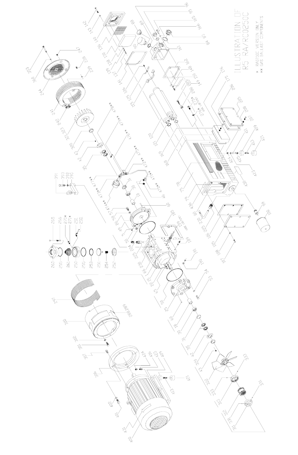
12, 13

14
requires an immediate change of the exhaust filter.
In order to replace the filter, remove the four
socket head cap screws (Ref. 155, 146) retaining the
exhaust port housing. Pull the housing off the
exhaust box and set it aside. Use a slotted head
screw driver to loosen the exhaust filter retaining
spring, then rotate and remove the spring. Pull the
filter cartridge (Ref. 120) out of the exhaust box.
To field test an exhaust filter element, remove it
from the pump, allow it to cool, clean the sealing
end (or O-ring end), and use compressed air to blow
through the element. Apply approximately 3 to 6
psi, which is the maximum allowable operating
pressure across the filter. Note: Use a shop rag to
seal off the connection between the air hose and the
filter. If you can blow through it, the element is
good. If not, discard it and install a new one. The
filter cannot be cleaned successfully. Visually
inspect the filter element for cracks.
Reinstall the filter elements. Make sure the open
end of the element is properly seated down in its
recess in the exhaust box (see Figure 3) with the O-
ring (Ref. 121) correctly positioned. Retain the filter
with the spring clip, tighten the tension screw until
the filter is secure. Place the exhaust port gasket and
housing in position on the exhaust box and retain
with the cap screws.
3.4 Vacuum Inlet Filter
If the pump is equipped with a special vacuum
inlet filter in applications where powder, dust or grit
is present, the filter cartridge should be cleaned on a
weekly basis, or as required, depending on the
amount of foreign particles to which the pump is
exposed.
3.5 Maintenance Chart
Daily: Visually check oil level (see 3.1.1 and
3.1.2).
Weekly: Check oil for contamination (see
3.1.3). Inspect inlet filter (see Section 3.4).
Every three (3) or four (4) months, 500 to 750
hours of operation, or as necessary: See 3.1.3 and
1.5. Drain and discard oil from the hot pump.
Replace the automotive-type oil filter and refill with
fresh oil through the fill plug (see 3.1.2 through
3.1.3 and 3.2).
Every nine (9) to twelve (12) months, or as
necessary: Replace exhaust filter elements (see
3.3).
3.6 Overhaul Kit/Filter
An overhaul kit containing a set of gaskets and
O-rings, vanes, bearings and bearing sleeves, shaft
seals and taper pins, is available from the factory.
Also, a filter kit containing oil drain plug, gas-
kets, automotive type oil filter (where applicable),
exhaust filter, and exhaust filter, is available from
the factory.
When ordering, please specify pump size and
model (a 3-digit suffix after size), and serial number.
4.0 TROUBLESHOOTING
4.1 Trouble
Pump does not reach “blank-off” pressure which
is the lowest absolute pressure (best vacuum) when
running with the inlet closed via a blank flange or a
valve; or the pump takes too long to evacuate the
system. “Blank-off” pressure can be measured by
using a good quality capsule gauge.
4.1.1 Possible Cause
Contaminated oil is by far the most common
cause of not reaching the ultimate pressure.
Remedy:
Shut off pump, after operating temperature has
been reached, drain the warm oil from pump and
exchange automotive-type oil filter (where applica-
ble), if necessary. Flush and fill pump with new oil
and take new “blank-off” measurement after operat-
WARNING: Do not inhale through the filter
or allow your mouth to come in direct contact
with the filter.

ing temperature is reached (at least 20-30 minutes).
4.1.2 Possible Cause
Vacuum system or vacuum piping not leak-tight.
Remedy:
Check hose and pipe connections for possible
leak.
4.1.3 Possible Cause
Wire mesh inlet screen plugged (Ref. 261).
Remedy:
Clean wire mesh inlet screen. Install inlet filter
if problem repeats frequently.
4.1.4 Possible Cause
No oil or not enough oil in oil reservoir.
Remedy:
Shut off the pump, add the necessary oil, or if oil
seems contaminated, drain balance of oil from
pump, exchange automotive oil filter, and refill with
fresh oil.
4.1.5 Possible Cause
Automotive-type oil filter is dirty or clogged
(where applicable).
Remedy:
Replace automotive-type oil filter, exchange oil,
if necessary, and refill with fresh oil.
4.1.6 Possible Cause
Inlet valve plate (Ref. 251) stuck in closed or
partially open position due to contamination.
Remedy:
Disassemble inlet valve and screen. Clean as
required.
4.1.7 Possible Cause
Oil tubing defect and/or leaking. Oil return line
broken on RC model.
Remedy:
Replace or retighten the oil fittings or oil tubing.
Replace only with same size tubing.
4.1.8 Possible Cause
Shaft seal leaking.
Remedy:
Replace the shaft seal following disassembly
and assembly steps outlined in the Maintenance and
Repair Manual. Check the shaft seal. It should have
a spring installed inside and around the shaft sealing
lip.
4.1.9 Possible Cause
Exhaust valve (Ref. 159) is not properly seated
or it is partially stuck open.
Remedy:
Follow disassembly and assembly steps outlined
in the Maintenance and Repair Manual.
4.1.10 Possible Cause
The vanes are blocked in the rotor or are other-
wise damaged.
Remedy:
Free vanes or replace with new ones following
disassembly and assembly steps outlined in the
Maintenance and Repair Manual.
4.1.11 Possible Cause
Radial clearance between the rotor and cylinder
is no longer adequate.
15

Remedy:
Follow disassembly and assembly steps outlined
in the Maintenance and Repair Manual on resetting
the radial clearance correctly.
4.1.12 Possible Cause
Internal parts worn or damaged.
Remedy:
Follow disassembly and assembly steps outlined
in the Maintenance and Repair Manual and replace
worn or damaged parts.
4.1.13 Possible Cause on RC Models Only
The oil return line (Ref. 290) is connected
directly to atmospheric pressure in the exhaust area.
On small model pumps, a fairly large amount of air
is sucked through the oil return line, and it may not
be possible to reach 15 torr or 29.4 inches Hg.
blank-off on the inlet of the pump under these con-
ditions.
Blank-off of 29.4 inches Hg or 15 torr can be
reached by temporarily disconnecting and closing
the oil return line; also by squirting oil through the
exhaust opening into the exhaust filter area. Oil will
be sucked into the oil return line, and no air will
reach the inlet, thus affecting the "blank-off' pres-
sure.
4.2 Trouble
Pump will not start.
4.2.1 Possible Cause
Motor does not have proper supply voltage or is
overloaded; motor starter overload settings are too
low or wrong setting; fuses are burned; or wire is
too small or too long, causing a voltage drop at the
pump.
Remedy:
Check correct supply voltage; check overload
settings in motor starter for size and setting accord-
ing to motor nameplate data; check fuses; and install
proper size wire. If ambient temperature is high, use
larger size overloads or adjust setting 5% above
nominal motor nameplate value.
4.2.2 Possible Cause
Pump or motor is blocked.
Remedy:
Remove fan cover and try to turn pump and
motor by hand. If frozen, remove motor from pump
and check motor and pump separately. If pump is
frozen, disassemble completely per the Maintenance
and Repair Manual and remove foreign objects in
the pump or replace broken vanes.
4.3 Trouble
Pump starts, but labors and draws a very high
current.
4.3.1 Possible Cause
Oil too heavy (viscosity too high) or ambient
temperature below 5 degrees C (41°F).
Remedy:
Change to R580 vacuum oil if very cold, or
warm up oil before filling.
4.3.2 Possible Cause
Pump runs in the wrong direction.
Remedy:
Check for correct rotation which is counter-
clockwise when looking at the motor from the
motor's fan side.
4.3.3 Possible Cause
Pump is overfilled with oil or the wrong kind of
oil is used.
16

Remedy:
Correct the oil level and quality per Section 1.5
and use recommended motor oil.
4.3.4 Possible Cause
Exhaust filters in exhaust chamber are clogged
and appear burned black with pump oil.
Remedy:
Replace exhaust filters, maintain proper oil con-
dition, oil level, and use only Busch recommended
vacuum oil.
4.3.5 Possible Cause
The exhaust filter is clogged due to process
material.
Remedy:
Contact the factory for recommendation or prop-
er filter cartridge.
4.3.6 Possible Cause
Loose connection in motor terminal box; not all
motor coils are properly connected. Motor operates
on two phases only.
Remedy:
Check motor wiring diagram for proper hookup,
especially on motors with six internal motor wind-
ings, tighten and/or replace loose connections.
4.3.7 Possible Cause
Foreign particle in pump, vanes broken, bearing
seizing.
Remedy:
Follow disassembly and assembly steps outlined
in the Maintenance and Repair Manual and remove
foreign parts, and replace vanes and bearings.
4.4 Trouble
Pump smokes at the exhaust side or expels oil
droplets from the exhaust.
4.4.1 Possible Cause
Exhaust filter is not properly seated with O-ring
(Ref. 121) in filter base or filter material is cracked.
Remedy:
Check condition and placement of exhaust fil-
ters in filter base. Replace if necessary.
4.4.2 Possible Cause
Exhaust filter is clogged with foreign particles.
Remedy:
Replace exhaust filter. Install other factory rec-
ommended filter cartridges if pump application
requires other filter cartridges.
4.4.3 Possible Cause
The oil return valve (Ref. 275) is not properly
working, clogged. Proper function is that when
blowing into check valve, it should close. When
applying vacuum on it, check valve should open.
Remedy:
Free or replace the oil return check valve.
4.4.4 Possible Cause
If RA Series vacuum pumps run continuously
over 8 hours without ever being shut down, it may
be possible that oil accumulates behind the exhaust
box cover (Ref. 275) to the extent that oil is blown
out of the exhaust with the exhaust gas.
Remedy:
Shut pump down during break periods or install
an additional oil return line assembly. Check that oil
return valve (Ref. 275) is free and drains oil back
into pump when RA Series pump is stopped.
WARNING: Do not apply pressure or vacu-
um by mouth.
17

4.4.5 Possible Cause
Oil return line (Ref. 290) on RC Standard pump
is clogged or broken.
Remedy:
Free clogged line, replace broken line, but only
with proper size, and check that oil is pumped out of
oil sump while vacuum pump is operating.
NOTE: An oil filling plug with pressure gauge is
provided on all R5 Series pumps, so that the pres-
sure in front of the exhaust filters can be monitored.
The green field indicates that the filters are still
effective. Any back pressure close to the red field
requires immediate change of the exhaust filter (Ref
120).
4.5 Trouble
Pump runs very noisly.
4.5.1 Possible Cause
Coupling insert worn.
Remedy:
Replace coupling insert in motor/pump cou-
pling.
4.5.2 Possible Cause
Bearing noise.
Remedy:
Follow disassembly and assembly steps outlined
in the Maintenance and Repair Manual and replace
bearings.
4.5.3 Possible Cause
Vanes stuck.
Remedy:
Follow disassembly/assembly instructions out-
lined in the Maintenance and Repair Manual and
replace vanes.
4.6 Trouble
The pump runs very hot. See Technical Data for
typical oil sump temperature.
4.6.1 Possible Cause
Not enough air ventilation to the pump.
Remedy:
Clean motor and pump air grills. Do not install
the pump in an enclosed cabinet unless a sufficient
amount of fresh air is supplied to the pump. On
pumps with oil cooling coils, clean outside fin
assembly. Bring ambient air temperature down.
4.6.2 Possible Cause
Automotive-type oil filter clogged and pump
does not receive enough oil.
Remedy:
Change automotive oil filter.
4.6.3 Possible Cause
Not enough oil in oil reservoir or badly burned
oil is used for pump lubrication.
Remedy:
Drain and refill only with non-detergent oil,
increase oil change intervals.
NOTE: On some high temperature applications,
it may be necessary to change to a high temperature
oil such as R590 or R570. Contact the factory for
recommendations.
4.7 Trouble
Pump is seized.
4.7.1 Possible Cause
Pump operated without oil and vanes broke.
18

Remedy:
Disassemble and exchange vanes as outlined in
the Maintenance and Repair Manual.
4.7.2 Possible Cause
Pump was operated for an extended period of
time in the wrong rotation.
Remedy:
Inspect vanes and replace.
4.7.3 Possible Cause
Liquid carryover into the pump cylinder broke
vanes while pump was running, or oil broke vanes
on start-up.
Remedy:
(a) Install condensate trap on the inlet of the
pump.
(b) Pump was overfilled with oil in oil reservoir.
Follow oil filling procedure (see Section 1.5) and do
not overfill.
(c) Built-in anti-suck-back valve (Ref. 250
through 255) leaking while pump was shut down
and vacuum was left in manifold. Clean valve seat
and check that anti-suck-back valve holds vacuum
on inlet when pump is shut down.
(d) Two pumps or a receiver is on the same main
line. Install a manual or automatic operated valve in
front of each pump.
4.8 Trouble
Automotive-type oil filter (Ref. 100) does not
get warm within two to five minutes when cold
pump is started.
4.8.1 Possible Cause
Automotive-type oil filter is clogged.
Remedy:
Replace automotive-type filter per Section 3.2
and exchange oil per Section 1.5.
4.8.2 Possible Cause
Wrong automotive-type filter is used and/or oil
lines leading to pump are clogged.
Remedy:
Use only automotive filter as listed in Section
3.2 and blow lines free.
19

5.0 LIMITED STANDARD WARRANTY
Busch, Inc. warrants that all products furnished
by it are free from defects in material and work-
manship at the time of shipment for a period of 18
months from the date of shipment, or 12 months
from the date of installation, whichever occurs first.
Claims must be made during that period and are lim-
ited to the replacement or repair of parts claimed to
be defective.
In the case of components purchased by Busch,
Inc., such as starters, controls, mechanical seals,
motors, couplings, etc., the warranty of that manu-
facturer will be extended to the purchaser in lieu of
any warranty by Busch, Inc. The replacement of
wear items including, but not limited to, seals, bear-
ings, couplings, exhaust cover gaskets, oil drain
plugs, oil fill plugs etc., made in connection with
normal service, are not covered by this Warranty.
The Limited Standard Warranty is valid only
when the product has been properly installed, used
in a normal manner, and serviced according to the
operating manual. This warranty shall not extend to
products that have been misused, neglected, altered,
or repaired without factory authorization during the
warranty period. We highly recommend the use of
Busch oils and parts to achieve documented per-
formance and efficient operation. The use of oils or
parts other than Busch could limit the life expectan-
cy of the equipment and could void any warranties
if they are the cause of any damage. Operating con-
ditions beyond our control such as improper voltage
or water pressure, excessive ambient temperatures,
or other conditions that would affect the perform-
ance or life of the product will also cause the war-
ranty to become void.
Permission to return parts for warranty repair
must be obtained, and all returns must be prepaid to
the factory. If, after examination, the product or part
is found to be defective, it will be repaired or
replaced on a no-charge basis and returned, FOB the
factory. If it is determined that the Warranty has not
been breached by Busch, Inc., then the usual charges
for repair or replacement will be made, FOB the fac-
tory. Parts or products that are obsolete or those
made to special order are not returnable.
This Limited Standard Warranty applies only to
the above and is for the period set forth. Busch,
Inc.'s maximum liability shall not, in any case,
exceed the contract price for the product, part, or
component claimed to be defective; and Busch, Inc.
assumes no liability for any special, indirect, or con-
sequential damages arising from defective equip-
ment.
THERE ARE NO WARRANTIES IMPLIED
OR EXPRESSED THAT EXTEND BEYOND
THOSE CONTAINED IN THIS LIMITED
STANDARD WARRANTY.
Note: For extended warranties on your new equip-
ment contact Busch, Inc. Headquarters at:
1-800-USA-PUMP
20

21
* Maximum oil temperature with 80°F ambient temperature and no supplemental oil cooling.
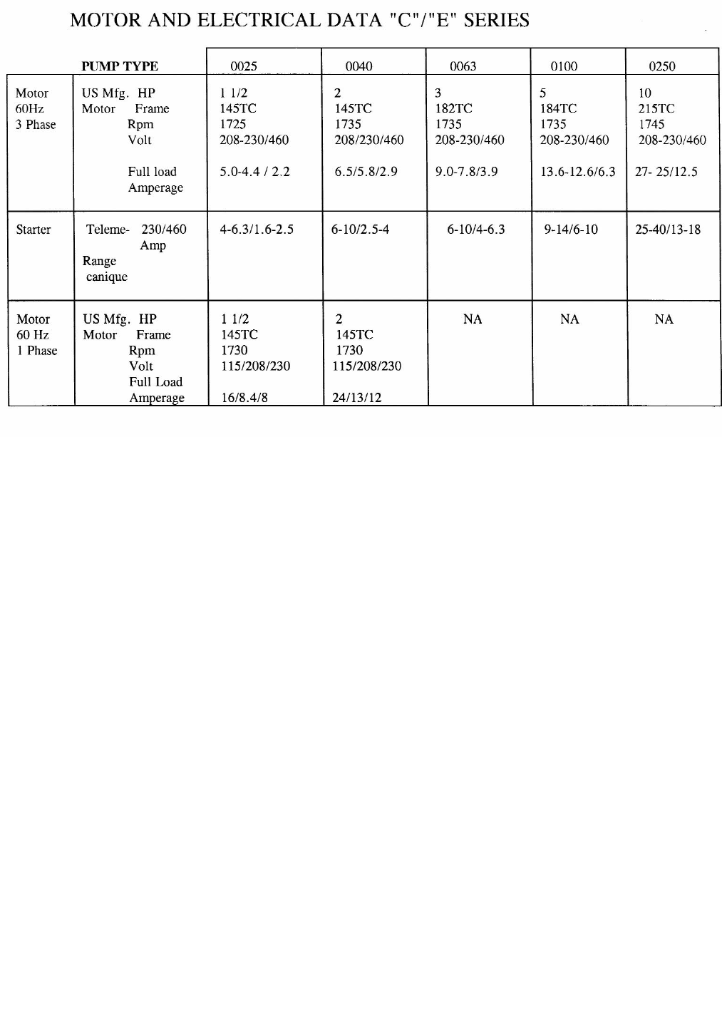
22

Busch Inc. Factory Service Centers
California Illinois
Kurt Kauffman Steve Looman
13826 Struikman Road 430 Windy Point Drive
Cerritos, CA 90703 Glendale Heights, IL 60139
562-926-8422 630-545-1310
New Jersey
Puerto Rico
Jose Concepcion Carlos Ortiz
39 Davis Street #420 E. Street, Suite 4
South Plainfield, NJ 07080 Minillas Industrial Park
908-561-3233 Bayamon, PR 00959-1901
787-798-5045
T
exas Virginia
Dave Parsons Clayton McClenny
15411 Vantage Pkwy W., Suite 216 516 Viking Drive
Houston, TX 77032 Virginia Beach, VA 23452
281-449-2381 757-463-7800

Installation and Operating
Instructions
Rotary Vane Vacuum Pumps
R 5 RA 0165, 0205, 0255 and 0305 D
Busch, Inc.
516 Viking Drive
Va. Beach, VA 23452
Phone: (757) 463-7800
Fax: (757) 463-7407
P/N 0872.911.978/ 0806

TABLE OF CONTENTS
Page
GENERAL 2
Identification 2
Operating Principles 2
1.0 INSTALLATION 2
1.1 Unpacking 2
1.2 Location 2
1.3 Power Requirements 2
1.4 Vacuum Connections 3
1.5 Oil Filling 3
2.0 OPERATION 4
2.1 Start-up 4
2.2 Gas Ballast 4
2.3 Process Gas 4
2.4 Stopping Pump 4
2.5 Water-Cooled Pumps (optional) 4
2.6 Oxygen Service Pumps 5
3.0 MAINTENANCE 5
3.1 Pump Oil 5
3.1.1 Oil Level 5
3.1.2 Oil Type and Quantity 6
3.1.3 Oil and Filter Change 6
3.1.4 Oil Flushing Procedure 6
3.2 Automotive-Type Oil Filter 6
3.3 Exhaust Filter 7
3.4 Inlet Flange 8
3.5 Vacuum Inlet Filter (Optional) 8
3.6 Maintenance Chart 8
3.7 Overhaul Kit/Filter Kit 8
4.0 TROUBLESHOOTING 8
5.0 LIMITED STANDARD WARRANTY 12
Technical Data 13
Parts List 14
Illustration of RA 0165/0205/0255/0305 15
Busch, Inc. Factory Service Center 16
We reserve the right to change the product at any time without any form of notification. The information in this pub-
lication is accurate to the best of our ability at the time of printing. Busch, Inc. will not be responsible for errors
encountered when attempting to perform tasks outlined in this publication which is copyright protected.
1

GENERAL
Identification
For model identification, see the nameplate mounted on
the side of the exhaust box.
This manual is written to cover installation and opera-
tion of the RA version of models 0165, 0205, 0255 and
0305 with a "D" appearing as the seventh character in
the model type number stamped into the nameplate.
For example it would appear as follows:
RA0XXX - D
XXX - XXXX
When ordering parts, it is helpful to include the identifi-
cation code stamped into the side of the cylinder as well
as the serial number from the nameplate.
Operating Principles
All reference (Ref. XX) numbers listed in the text and on
illustrations throughout this manual are related to the
drawings and parts list near the end of this publication.
R 5 Series, Single Stage, Rotary Vacuum Pumps are
direct-driven, air-cooled, oil-sealed rotary vane pumps
which operate as positive displacement pumps (see
Fig. 1). They consist of a rotor positioned eccentrically
in a cylindrical stator (see Fig. 2). When the rotor spins,
centrifugal force pushes the vanes, which glide in slots,
towards the wall of the cylinder. The rotor has three
vanes which divide the pump chamber into three seg-
ments. The gas to be pumped enters at the inlet port,
passes through the inlet screen and the open anti-suck-
back valve into the pump chamber. As the rotor rotates,
the inlet aperture is closed, the gas is compressed and
forced out through one-way valves between the pump
cylinder and the exhaust box. Differential pressure con-
stantly causes oil to be pressed into the compression
chambers. The gas/oil mixture is separated by the dis-
charge filters (Ref. 120). The oil-free medium is dis-
charged through the exhaust cover plate (Ref. 140) to
atmosphere. This operation is repeated three times
each revolution.
1.0 INSTALLATION
1.1 Unpacking
Inspect the box and pump carefully for any signs of
damage incurred in transit. R 5 Pumps pass a rigorous
operating test in the factory and are packed carefully to
avoid transit damage. Since all pumps are ordinarily
shipped FOB our factory, such damage is the normal
responsibility of the carrier and should be reported to
them.
Remove any nuts from the bottom of the box/crate and
pull the pump out of the container using a suitable lifting
device and the lifting eye bolt (Ref. 391). Then,
unscrew any remaining studs that secured the bottom
of the rubber feet to the bottom of the crate.
The inlet port of the pump is covered with a plastic cap
prior to shipment to prevent dirt and other foreign mate-
rial from entering the pump. Do not remove this cover
until the pump is actually ready for connection to your
system.
1.2 Location
The pump must be installed in a horizontal position on
a level surface so that the pump is evenly supported on
its rubber feet. Allow sufficient air space between the
pump and any walls or other obstructions; adequate
ventilation must be provided for the fans on the pump
and motor (i.e., do not locate the pump in a stagnant air
location).
Whenever the pump is transported, be sure to drain the
oil prior to shipping to avoid vane breakage when
restarting the pump.
Do not tip the pump over if it is filled with oil.
Locate the pump for easy access to the oil sight glass
(Ref. 83) in order to inspect and control the oil level
properly. Allow clearance at the exhaust flange area to
provide service access to the exhaust filters.
1.3 Power Requirements
The schematic diagram for the electrical connection is
located in the junction box or on the nameplate of the
pump motor.
Fig. 1 - R 5 0255 D Pump
All R 5 series pumps are designed to handle air.
Vapor in the air stream can be tolerated when the
pump is operated within certain operating parameters
as defined by Busch, Inc. Engineering (see Section
2.2 - Gas Ballast). When you desire to use the pump
on an air stream that contains vapors, contact Busch,
Inc. Engineering for operating recommendations; oth-
erwise, the warranty could be void.
2

The motor must be connected according to the electri-
cal codes governing the installation. The power supply
must be routed through a fused switch to protect the
motor against electrical or mechanical overloads. The
motor starter has to be set consistent with the motor
current listed on the motor nameplate.
If the pump is supplied with a manual motor starter, it is
preset at the factory in accordance with the customer’s
specification. For other voltage requirements, contact
the factory for motor and/or starter information.
Note: See the motor manufacturer’s manual for start-
up maintenance of the motor.
Correct direction of rotation is marked by an arrow on
the motor fan housing and is counterclockwise when
looking at the motor from the motor's fan side.
1.4 Vacuum Connections
Use a line size to the vacuum system that is at least as
large as that of the pump inlet. Smaller lines will result
in lower pumping speeds than the rated values.
Install a drip leg and drain on the vertical pipe near the
pump inlet. Drain the drip leg often to prevent conden-
sation from entering the pump. Also, when installing
discharge piping, a drip leg should be installed.
If more than one vacuum pump or a receiver tank is
connected to a common main line, each pump should
have its own manual or automatic operated shut-off
valve or positive action check valve. The built-in anti-
suck-back valve should not be used as a shut-off valve
for the vacuum system.
Remove the plastic protective cap from the inlet port
prior to connection of the pump to the system. Vertical
connection of the vacuum line can be made directly to
the pump inlet (Ref. 260).
The type and size of the inlet connections of the R 5
Series pump is shown in the TECHNICAL DATA page
12.
If the gas that is pumped contains dust or other foreign
solid particles, a suitable (10 micron rating or less) inlet
filter should be connected to the inlet port. Consult the
factory for recommendations.
1.5 Oil Filling
The pump is shipped without oil. After level installation,
after correct rotation has been established and with the
pump switched "off" and secured against accidental
start-up, fill the pump with the recommended vacuum
oil through the oil filling port (Ref. 88), observing the
"MAX" and "MIN" position at the oil sight glass (Ref.
83).
Non-detergent oil should be used. Do not use
detergent motor oil as additives in detergent oil will
plug exhaust filter elements and shorten their life.
CAUTION: After the electrical connection
has been made, but before the pump is
filled with oil, the rotation of the motor
must be checked. Open the inlet port and
jog the motor briefly to make sure rotation
is correct. If it runs backwards and if it is
wired three phase power, reverse any two
leads of the three at the power connection.
CAUTION: Do not use the anti-suck-back
valve as a check or shut-off valve for your
vacuum system.
Fig. 2 - Basic R 5 RA0165, 0205, 0255 and 0305 D Series Pump
75
159
260
Inlet
1001522194958390
Oil
120
140
Exhaust
3

It is recommended that Busch R500 Series oil be used
to receive the best performance from your vacuum
equipment. R500 Series oil is a high quality vacuum oil
which will give longer running time between oil
changes, will provide better lubrication at high operating
temperatures, and will prolong the life of exhaust filter
elements. This oil can be obtained directly from Busch,
Inc. in Virginia Beach, Virginia.
The strict use of Busch oils and parts from the day of
purchase can extend the standard warranty to three
years. Contact Busch, Inc. in Virginia Beach, Virginia
for details. Refer to page 11 for the Limited Standard
Warranty.
For general applications, use R530 in most models cov-
ered by this manual. Use R590 or R570 in pumps that
are operated in high ambient temperatures (above
90°F) or when the oil can carbonize (turns black) before
the change interval. Contact the factory for recommen-
dations when using other oils.
The TECHNICAL DATA chart on page 13 gives the
approximate quantities of oil required for each pump.
The oil capacity chart should only be used as a guide,
since oil capacity may be slightly lower, depending on
whether the pump was filled previously, and whether all
components such as oil filter, oil lines, etc., were
allowed to completely drain. Use only the sight glass
reading for proper level. Never overfill!
For ambient operating temperatures lower than 41°F,
use Busch R580 synthetic oil. If this does not help
(where the pump has difficulty starting due to high oil
viscosity) contact the factory in Virginia Beach, Virginia.
Replace the oil fill plug (Ref. 88) and pressure gauge
(Ref. 90), making sure that the gasket (Ref. 89) is in
place and properly seated and secured. Pumps are
equipped with an exhaust pressure gauge as an inte-
gral part of the oil fill plug. Switch the power back into
the "on" position.
2.0 OPERATION
2.1 Start-up
Check rotation of the motor as described in Section 1.3
- Power Requirements.
Fill the pump with oil as described in Section 1.5 - Oil
Filling.
Start the pump and immediately close the inlet. Run the
pump for a few minutes before checking the oil level
again. With the pump shut off, the oil level should be
visible in the oil sight glass (Ref. 83), between the "MIN"
and "MAX" mark.
Add oil, if necessary, but only add it when the pump has
been shut off and the circulating oil has had sufficient
time to return to the oil sump.
2.2 Gas Ballast
R 5 Series RA 0165 through 0305 D pumps are
equipped with an adjustable gas ballast valve (Ref.
474). The adjustable gas ballast valve should normally
be left open. Its primary function is to prevent water
vapor from condensing in the pump. Condensation
causes emulsification of the oil, loss of lubricity, and
possible rotor seizure.
Check the gas ballast filter periodically to ensure that air
is flowing through it properly.
2.3 Process Gas
The R 5 series pumps are designed to pump air and are
not intended for use when water vapor is being
pumped. In some applications, when the quantity of the
water vapor is moderate, R 5 pumps have been used
with good results. On these occasions, the pump is run
until it is up to operating temperature before it is allowed
to pump the process gas. The pump is also operated
for a period of time off process and on air (to clear it of
process gas) before it is shut down. This operating
technique prevents the vapor from condensing in the
pump. Before attempting to pump a gas laden with
water vapor, contact Busch Engineering for advice.
2.4 Stopping Pump
To stop the pump, turn off the power. The pump has a
built-in anti-suck-back valve (Ref. 251 thru 255) to pre-
vent the pump from rotating backwards when it is shut
off.
Install a manual or automatic valve or check valve in
each pipe leading to each pump when multiple pumps
are pumping on a common header.
All R 5 Series pumps are vented internally to atmos-
pheric pressure through venting holes which are next to
the exhaust valve assembly.
2.5 Water-Cooled Pumps (Optional)
Water-cooled pumps are cooled by circulating the oil
WARNING: Keep the oil fill plug tight as
pressure in the exhaust box could cause
bodily injury if the plug is blown out. Do not
fill/add the pump with oil through the
exhaust/inlet ports as there is danger of
breaking the vanes!
CAUTION: Do not use the anti-suck-back
valve as a check or shut-off valve for your
vacuum system.
4
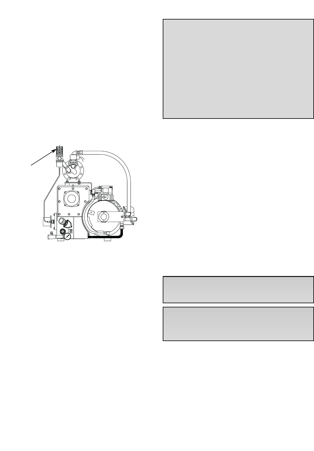
through a shell-and-tube type heat exchanger. The cir-
culation of the pump oil through the shell is created by
vacuum in the pump, but the circulation of the cooling
water through the tubes is thermostatically controlled.
The flow rate of the cooling water is controlled by a ther-
mostatically activated valve (see Fig. 3) that senses,
through a capillary bulb mounted in the exhaust box,
the pump's oil temperature as it is discharged from the
compression chamber. The valve will open at its set
point and close at approximately 3°F to 5°F below the
set point. The valve set point is adjustable as follows:
(a) Rotate the valve adjustment screw counter-
clockwise to cause the valve to open at a higher tem-
perature. This makes the pump run hotter.
(b) Rotate the valve adjustment screw clockwise to
make the valve open at a lower temperature. This
makes the pump run cooler.
The thermostatic valve can be manually opened by
inserting a screwdriver under each side of the spring
guide and prying the spring and guide upward away
from the valve body.
The water cooling option can be used to cool pumps
operating in high ambient temperatures, or it can be
used to maintain a pump at elevated temperatures to
prevent condensation inside the pump in wet applica-
tions. Contact Busch Engineering in Virginia Beach for
details.
2.6 Oxygen Service Pumps
Oxygen service pumps must be used in oxygen
enriched applications that are defined as any applica-
tion which has a process gas that is 25% or more oxy-
gen. If this pump is contaminated by organic com-
pounds do not attempt to use it on oxygen service until
it has been decontaminated.
These pumps have been manufactured, solvent
washed (to remove organic contaminants) and assem-
bled according to the latest technical standards and
safety regulations. If this pump is not installed properly
or not used as directed, a dangerous situation or dam-
age might occur.
It is mandatory that these operating instruc-
tions be read and understood prior to vacu-
um pump installation and start-up!
For overhaul/repair of oxygen service pumps,
Busch Inc. strongly recommends that all major repair
operations be conducted at the factory. Improper
handling of repairs could result in extreme
danger to personnel operating the pump.
3.0 MAINTENANCE
R5 Series, Single Stage, Rotary Vacuum Pumps require
very little maintenance; however, to insure optimum
pump performance, the following steps are recom-
mended.
3.1 Pump Oil
3.1.1
Oil Level
With the pump installed relatively level, make sure that
there is sufficient clean oil in the pump (see Section
1.5). The oil level should be observed on a daily basis
and/or after 8 hours of operation and should be replen-
ished if it drops below the 1/4 mark on the oil sight
glass.
Oil level readings should be done only when the pump
is turned off. Oil can be added to the oil fill port (Ref.
88) if the pump is shut off and the circulating oil has suf-
ficient time to return to the oil sump. The oil might
appear to be foamy, which is a normal phenomenon
with aerated oil.
Thermostat valve
Fig. 3 - Water Cooled Pump
WARNING: This pump is filled with a special
operating fluid. Do not use any other type
of fluid, oil and/or grease. Use one of the
following:
• Fomblin LC 250
• Tyreno Fluid 12/25V (perfluorinated poly
ether)
• KRYTOX ®Vacuum pump fluid by Du Pont
Company
If you have any questions, please phone our
Customer Service Department for more information.
CAUTION: Do not add oil while the pump is
running since hot unfiltered oil vapor may
escape through the oil fill port.
WARNING: Insufficient oil quantity in the
pump has the potential, under certain con-
ditions, to lead to self-ignition of the
remaining oil in the pump.
5

Under normal circumstances, it should not be neces-
sary to add or drain oil from the pump between recom-
mended oil changes.
A significant drop in oil level means there is an oil leak
or that an exhaust filter is broken, and the pump should
be smoking excessively. It is normal for the oil to be
foamy and light in color in an operating pump.
However, if the oil is milky colored, it is an indication
that water is present in the oil. Normally, by operating
the pump for an extended period, with the inlet suction
blanked off and the gas ballast open, the water will be
purged from the oil. If the oil is dark colored, it is con-
taminated or carbonized and must be changed.
Depending on the severity of the contamination, a thor-
ough flushing may be required. Contact the factory for
flushing oil (Busch R568) and instructions.
3.1.2
Oil Type and Quantity
See Section 1.5 and the Technical Data page 13 for
details on oil type and quantity.
3.1.3
Oil and Filter Change
Check the oil for contamination on a weekly basis by
shutting the pump off and draining some of the oil into
a small glass or a similar transparent container through
the oil drain port (Ref. 95).
Oil life is dependent upon the conditions to which it is
exposed. A clean, dry air stream and an oil operating
temperature under 210°F are ideal conditions. Oil must
be changed after the first 100 initial hours of operation.
After the initial oil change, and when using R530
(hydrocarbon oil), it is recommended that oil changes
are made every three (3) to four (4) months or 500 to
750 hours of operation, or as necessary if high heat is
contaminating the oil. The use of Busch R570 (syn-
thetic) or R590 (semi-synthetic) oil may significantly
extend the operating hours between oil changes; how-
ever, you may need to flush out the pump before chang-
ing. Contact the factory Service Department for advice
or refer to Section 3.1.4 for the flushing procedure.
To change the oil, the pump must be switched off and
ventilated to reach atmospheric pressure. Remove the
oil drain plug (Ref. 95) and drain the oil. Dispose of the
oil in compliance with local or national regulations.
When the oil stops draining, replace the oil drain plug.
Start the pump again for a few seconds. Stop the pump
once again, and then reopen the drain plug and dis-
charge any remaining oil.
Refasten the oil drain plug. Remove the oil filter (Ref.
100) and replace it with a new one using a Busch gen-
uine oil filter. Make sure to tighten the filter securely
against the aluminum sealing surface so that leaks will
not occur.
Excessive Heat
When the pump is subjected to operating conditions
that will cause the oil to be heated above 210°F, the oil
will carbonize and become contaminated after a rela-
tively low number of operating hours. The higher the
temperature, the quicker the oil becomes contaminated.
If the oil temperature is too severe, Busch R570 or
R590 synthetic oil should be used to withstand the ele-
vated temperatures. When changing to synthetic oil,
the pump should be flushed with Busch R568 oil.
Contact the factory for instructions on the flushing pro-
cedure. Auxiliary oil cooling is the most practical
approach to a severe heating problem.
Contaminated Air Stream
When the air stream contains solids and/or liquid that
contaminate the oil, the oil must be changed more
often. If the air stream contains a small percentage of
contaminates and/or they are slightly aggressive* (mild
acids, etc.), synthetic oil, such as Busch R570, will
resist breakdown better than the standard Busch R530.
The solution is to install a filter or knock-out pot to keep
the contaminates out of the pump.
*Process air streams with a large percentage of con-
taminates and/or are more than slightly aggressive
must use a chemical duty pump.
Oil change intervals can only be established by experi-
ence with the pump operating in the actual conditions
(see previous paragraph for some of the conditions).
Develop the oil change interval by periodically checking
an oil sample removed from the pump. When the oil
sample has become dark in color (from solids and car-
bonized particles) or is milky looking (from water), it is
time to discard it. As mentioned before, a thorough
flushing may be required.
CAUTION: When changing the oil and fil-
ters, it may be necessary to flush the pump
to remove any build-up of degraded oil from
the sumps, oil lines, radiators, etc. to
ensure proper oil flow through the pump.
Reduced oil flow, especially through radia-
tors and cooling coils, can cause mechani-
cal damage or extreme overheating which
could cause the oil vapors to ignite.
WARNING: Always take the necessary pre-
cautions concerning personal protective
equipment when changing oil and make
sure the pump is switched to the "off" so
that accidental starting will not occur. Oil
temperature can reach 212°F and may pose
a danger of scalding.
6

3.1.4 Oil Flushing Procedure
Flushing is needed under certain conditions. Some
pumps will be beyond flushing and will need to be over-
hauled.
To help determine if flushing is needed, observe the
condition of the oil as it is drained from the pump. Is it
black and tar like or contaminated in any way? Was the
pump noisy, overheating, or was the motor overload
shutting the pump off? How old is the pump and when
was the last time the oil was changed?
If the above conditions exist or you don't know when the
last oil change was performed further investigation is
needed. Also, when changing from one oil type such as
R530 to another type such as R590 or R570 it will be
beneficial to flush. Although the oils are compatible,
mixing a lesser grade oil such as R530 with a synthetic
oil like R570 will reduce the effectiveness of the syn-
thetic oil.
All of the oil will be removed and replaced with the
flushing oil (Busch R-568), and eventually that will be
replaced by whatever Busch oil is needed for your par-
ticular application. Have enough oil and oil filters on
hand for a couple of flushes. The following describes
the steps in the flushing procedure:
Shut the pump off and drain all the oil from the pump
and remove the access plates (Ref. 205) from the
exhaust box (Ref. 075). Remove the metal baffle (Ref.
078) and take a good look at the internal walls of the oil
sump. If the walls are discolored but have no build up
of any kind one can proceed with the flushing. If gelled
or burnt oil is clinging to the walls this material must be
scraped and removed prior to flushing. Proceed by
scraping and cleaning as much of the exhaust box as
possible. The more debris that is removed now the
more effective the flushing will be later. Re-install the
metal baffle, cover and proceed with the flushing. At
this point one must remember that the oil lines and oil
cooler might also be plugged to a point where no
amount of flushing will make a difference and a com-
plete overhaul will be the only option. Depending on
the severity of the oil contamination flushing may be a
last ditch effort.
Drain all of the oil from the pump. The more contami-
nated oil you remove now the more effective the oil
flushing will be.
Remove the oil filter (Ref. 100) and install a new one. It
is recommended that you do not change the exhaust fil-
ter or filters until after the flushing to prevent contami-
nation of any new filters.
Fill the exhaust box with the proper amount of flushing
oil (Busch R-568).
If possible run the pump with the inlet closed and off of
the process. Run the pump for approximately six hours,
shut the pump off and drain a small sample of oil into a
clear container.
Examine it. If it is clear to amber run the pump for
another six hours and examine it again. If after the first
six hours it is black drain it and fill again using another
new oil filter.
If after the second flushing the oil still remains black the
pump may have too much contaminated oil in it to flush
out properly. There may be residue remaining in the
lines and cooler that will not flush out. An overhaul will
be necessary.
If after the second six hour period the oil still remains
clear to amber in color drain it, change the oil filter and
fill with the regular oil. At this point also change the
exhaust filters.
Run the pump with a fresh charge of the oil to be used
in your application (not R-568), and monitor the operat-
ing conditions closely. Check for noise, overheating
and oil condition until a regular oil change schedule can
be established.
Do not let the oil turn black. Change it before it fails. If
the oil is kept in good condition the pump will last for
years. If the oil starts to turn black do not hesitate to
flush again. Keeping on top of the oil changes will pre-
vent costly overhauls.
If you are just switching from one type of oil to another
a single six hour flush is all that is necessary (follow the
above instructions). Remember to change to a new
exhaust filter or filters after the flushing and not before.
3.2 Automotive-Type Oil Filter
The pump is equipped with an automotive-type oil filter
(Ref. 100). When replacing the automotive-type oil fil-
ter, use only a Busch genuine filter.
Note: Make sure to tighten the Busch oil filter secure-
ly against the aluminum sealing surface so that leaks
will not occur.
3.3 Exhaust Filter
7
WARNING: Always wear safety glasses and
other appropriate personal protective
equipment when performing any mainte-
nance or repair to your R 5 pump.
WARNING: If the gas entering this pump is
a health hazard, use rubber gloves and all
necessary personal protection equipment
when performing the exhaust filter replace-
ment operation.

Exhaust filters (Ref. 120) should be checked monthly.
A pressure gauge (Ref. 90) is supplied with your R5
vacuum pump as part of the oil fill plug. This gauge has
a green field and a red field. A pressure within the
green field would indicate normal pressure. Any pres-
sure in the red field (for a continuos period of time)
requires an immediate change of the exhaust filter(s).
Every nine (9) to twelve (12) months, or as necessary,
replace the exhaust filter elements. The service life of
the exhaust filters varies widely with pump application.
It is only necessary to change the filters when the ele-
ments become clogged with foreign material or burned
oil. Indications of clogged filters are smoke and oil mist
coming from the pump exhaust or higher than normal
motor current.
In order to replace the exhaust filters, unscrew the
screws and washers (Ref. 142/143) from the exhaust
cover plate (Ref. 140). Remove the cover plate and
gasket (Ref. 141).
Remove the distance pin (Ref. 137), the baffle strainer
(Ref. 130) and the sheet metal plate (Ref. 136).
Remove the discharge filter assembly by unscrewing
the nut (Ref. 134) and removing the lockwasher (Ref.
132). Carefully slide the assembly out of the exhaust
box (Ref. 75). Stand the filter assembly up on a clean
flat surface.
To have access to the individual filters, unscrew the two
cylinder cover screws (Fig. 126), and remove the two
lockwashers (Ref. 128) and the exhaust filter grip plate
(Ref. 115).
Remove the exhaust filters (Ref. 120) and O-rings (Ref.
121). Remove the filter support (Ref. 118) and O-rings
(Ref. 119).
Replace the support and O-rings with new ones. Make
sure that the O-rings are fitted securely and that the fil-
ter elements (Ref. 120) fit securely into the depressions
on the filter support (Ref. 118). The indicating arrow on
each element must be pointing upward toward the top
of the exhaust box after the assembly has been
installed.
Carefully position the filter support tube (Ref. 133)
between the exhaust filter grip (Ref. 115) and the filter
support without displacing the filters from their seated
position in the filter support. Install the two lockwashers
(Ref. 128) and two screws (Ref. 126).
Insert the support and filter assembly into the exhaust
box using the stud (Ref. 131) as a guide. The stud
should slide through the hole in the support (Ref. 133).
Secure the assembly with the lockwasher (Ref. 132)
and hexagon nut (Ref. 134).
Reinstall the sheet metal plate (Ref. 136) and the baffle
strainer (Ref. 130) into the guide track of the exhaust
box (see Fig. 4). Press to the bottom of the exhaust
box. Make sure that the baffle strainer touches all sides
of the exhaust box. Insert the distance sleeve (Ref.
137) into the two grooves. This holds the sheet metal
plate and baffle strainer in place.
Inspect the exhaust box end cover gasket (Ref. 141) for
damage and replace if damaged. With the gasket in
place, secure the exhaust cover end plate (Ref. 140) to
the exhaust box using eight hex head cap screws (Ref.
142) and eight lockwashers (Ref. 143).
To field test an exhaust filter element, remove it from
the pump, allow it to cool, clean the sealing end (or O-
ring end), and use compressed air to blow through the
element. Apply approximately 3 to 6 psi, which is the
maximum allowable operating pressure across the fil-
ter.
Use a shop rag to seal off the connection between the
air hose and the filter.
If you can blow through it, the element is good. If not,
discard it and install a new one. The filter cannot be
cleaned successfully. Visually inspect the filter element
for cracks.
Reinstall the filter elements as described previously.
3.4 Inlet Flange
The standard inlet flange assembly contains an inlet
screen (Ref. 261) which may require occasional clean-
ly. The frequency of cleaning can only be determined
8
Fig. 4 - Exhaust Filters and Strainer
Track
136
130
137
120
115
134
CAUTION: Excessively contaminated and/or
clogged exhaust filters could possibly lead
to elevated pump temperatures which
could, under certain circumstances, cause
the lubricating oil to self-ignite.

by experience and is affected by hours of operation and
particle size being trapped. An optional vacuum inlet fil-
ter is offered and can help minimize the need or fre-
quency of cleaning the inlet screen.
To clean the screen, disconnect the flange from the
process piping. Remove the four screws and lock-
washers (Ref. 265/266). Remove the inlet flange (Ref.
260). Remove the screen (Ref. 261) and clean with
compressed air. After cleaning, install the screen and
inlet securing them with the screws and lockwashers.
Make sure the O-ring (Ref. 265) is in place prior to
securing the screws. Reattach the process piping to
the inlet.
3.5 Vacuum Inlet Filter (optional)
If the pump is equipped with an optional special vacu-
um inlet filter in applications where powder, dust or grit
is present, the filter cartridge should be cleaned on a
weekly basis, or as required, depending on the amount
of foreign particles to which the pump is exposed.
To clean the inlet filter, unsnap the lid clamps or remove
the knobs and lift off the filter lid. Remove cartridge,
being careful not to knock any foreign particles present
inside the canister into the pump suction. Clean foreign
particles from the canister with an air hose, and care-
fully back flush the filter cartridge with shop air. If the fil-
ter cartridge has been subjected to moisture or is
extremely dirty, it may need replacement.
3.6 Maintenance Chart
Note: See the motor manufacturer’s manual for the
periodic motor maintenance.
Note: Lack of proper maintenance can result in
blocked filters, radiators, oil lines, etc. This condition
can lead to excessive heat causing mechanical failure
or ignition of the oil vapors.
Daily: Visually check oil level (see 3.1.1 and 3.1.2).
Weekly: Check oil for contamination (see 3.1.3).
Inspect inlet filter (see Section 3.5).
Every three (3) or four (4) months, 500 to 750
hours of operation, or as necessary: See 3.1.3
and 1.5. Drain and discard oil from the hot pump.
Replace the automotive-type oil filter and refill with
fresh oil through the fill plug (see 3.1.2 through 3.2).
Every nine (9) to twelve (12) months, or as
necessary: Replace exhaust filter elements (see
3.3).
As necessary: Check and/or clean the standard inlet
screen. If the optional inlet filter is used, replace the fil-
ter material as practice determines.
As necessary: The radiator (Ref. 241), fan hood
(Ref. 244) and motor cover should be inspected regu-
larly for debris. Soiling prevents cool air intake and may
lead to overheating of the pump.
3.7 Overhaul Kit/Filter Kit
An overhaul kit containing a set of gaskets and O-rings,
vanes, bearings and bearing sleeves, shaft seals and
taper pins, is available from the factory. Also, a filter kit
containing oil drain plug, gaskets, automotive type oil fil-
ter, exhaust filter and synthetic baffle strainer is avail-
able from the factory. When ordering, please specify
pump size and model (a 4-digit suffix after size), and
serial number.
4.0 TROUBLESHOOTING
4.1 Trouble
The pump does not reach "blank-off" pres-
sure which is the lowest absolute pressure
(best vacuum) when running with the inlet
closed via a blank flange or a valve; or the
pump takes too long to evacuate the system.
"Blank-off" pressure can be measured by
using a good quality capsule gauge.
Possible Cause: Contaminated oil is by far the most
common cause of not reaching the ultimate pressure.
Remedy: Shut off the pump, after the operating tem-
perature has been reached, drain the warm oil from
pump and exchange the automotive-type oil filter
(where applicable), if necessary. Flush and fill the
pump with new oil and take a new "blank-off" measure-
ment after operating temperature is reached (at least
20-30 minutes).
Possible Cause: The vacuum system or vacuum
piping is not leak-tight.
Remedy: Check the hose and pipe connections for
possible leak.
Possible Cause: The wire mesh inlet screen is
plugged (Ref. 261).
Remedy: Clean the wire mesh inlet screen. Install an
inlet filter if the problem repeats frequently.
Possible Cause: No oil or not enough oil in the oil
reservoir.
Remedy: Shut off the pump, add the necessary oil, or
if oil seems contaminated, drain the balance of the oil
from the pump, exchange the automotive oil filter, and
refill with fresh oil. Flush if necessary.
Possible Cause: The automotive-type oil filter is dirty
9

or clogged (where applicable).
Remedy: Replace the automotive-type oil filter,
exchange the oil, if necessary, and refill with fresh oil.
Possible Cause: The inlet anti-suck-back valve plate
(Ref. 251) is stuck in closed or partially open position
due to contamination.
Remedy: Disassemble the inlet valve and screen.
Clean as required.
Possible Cause: The oil tubing fittings are loose and
leaking.
Remedy: Replace or retighten the oil fittings or oil tub-
ing. Replace only with same size tubing.
Possible Cause: Shaft seal leaking.
Remedy: Replace the shaft seal following disassem-
bly and assembly steps outlined in the Maintenance
and Repair Manual. Check the shaft seal. It should
have a spring installed inside and around the shaft seal-
ing lip.
Possible Cause: Exhaust valve (Ref. 159) is not
properly seated or it is partially stuck open.
Remedy: Contact the nearest Busch Factory Service
Center for instructions.
Possible Cause: Vanes are blocked in rotor or are
otherwise damaged.
Remedy: Free vanes or replace with new ones.
Contact the nearest Busch Factory Service Center for
instructions.
Possible Cause: The radial clearance between the
rotor and cylinder is no longer adequate.
Remedy: Contact the nearest Busch Factory Service
Center for instructions.
Possible Cause: The internal parts are worn or dam-
aged.
Remedy: Contact the nearest Busch Factory Service
Center for instructions.
Possible Cause: The inlet filter is clogged due to
process material.
Remedy: Contact the factory for recommendation on
proper filter cartridge.
4.2 Trouble
Pump will not start.
Possible Cause: The motor does not have the prop-
er supply voltage or is overloaded; the motor starter
overload settings are too low or are the wrong setting;
fuses are burned; or the wire is too small or too long,
causing a voltage drop at the pump.
Remedy: Check correct supply voltage; check over-
load settings in motor starter for size and setting
according to motor nameplate data; check fuses; and
install proper size wire. If the ambient temperature is
high, use larger size overloads or adjust the setting 5%
above nominal motor nameplate value.
Possible Cause: The pump or motor is blocked.
Remedy: Remove the fan cover and try to turn pump
and motor by hand. If frozen, remove the motor from
the pump and check the motor and the pump separate-
ly. If the pump is frozen, contact the nearest Busch
Factory Service Center for instructions.
4.3 Trouble
The pump starts, but labors and draws a
very high current.
Possible Cause: The oil is too heavy (viscosity too
high) or the ambient temperature is below 5 degrees C
(41°F).
Remedy: Change to R580 vacuum oil if very cold, or
warm up the oil before filling.
Possible Cause: Pump is running in the wrong direc-
tion.
Remedy: Check for the correct rotation which is coun-
terclockwise when looking at the motor from the motor's
fan side. Reverse any two leads on the motor to
change the direction of rotation.
Possible Cause: The pump is overfilled with oil or
the wrong kind of oil is used.
Remedy: Correct the oil level and quality per Section
1.5 and use recommended motor oil.
Possible Cause: Exhaust filters in exhaust chamber
are clogged and appear burned black with pump oil.
Remedy: Replace the exhaust filters, maintain proper
oil condition, oil level, and use only Busch recommend-
ed vacuum oil and filters.
Possible Cause: Loose connection in motor terminal
box; not all motor coils are properly connected. The
motor operates on two phases only.
Remedy: Check the motor wiring diagram for proper
hookup, especially on motors with six internal motor
10

windings, tighten and/or replace loose connections.
Possible Cause: Foreign particle in pump, vanes
broken, bearings seized.
Remedy: Contact the nearest Busch Factory Service
Center for instructions.
4.4 Trouble
Pump smokes at the exhaust side or expels
oil droplets from the exhaust.
Possible Cause: Inlet to pump is in a wide open con-
dition.
Remedy: Do not operate pump at high inlet pressures
for more than a few minutes (pressures = 0.00-10.0" Hg
vac.)
Possible Cause: The exhaust filter is not properly
seated with the O-ring (Ref. 121) in filter base or the fil-
ter material is cracked.
Remedy: Check the condition and check for proper
seating of the exhaust filters. Replace if necessary.
Also, check the filter spring clips for tightness.
Possible Cause: The exhaust filter is clogged with
foreign particles.
Remedy: Replace the exhaust filter.
Possible Cause: The oil return float valve (Ref. 194)
is not working properly.
Remedy: Make sure the float valve and oil return line
are not plugged. Replace components if necessary.
4.5 Trouble
Pump runs very noisily.
Possible Cause: Coupling insert is worn.
Remedy: Replace the coupling insert in motor/pump
coupling.
Possible Cause: Bearing noise.
Remedy: Contact the nearest Busch Factory Service
Center for instructions.
Possible Cause: Vanes stuck.
Remedy: Contact the nearest Busch Factory Service
Center for instructions. Use only the recommended
Busch oil and change oil more frequently.
4.6 Trouble
The pump runs very hot. See Technical Data
for typical oil sump temperature.
Note: The oil temperature with a closed inlet should be
approximately 185-225°F depending on pump type. At
24 in. Hg, the oil in the pump can go above 225°F.
These values are taken at an ambient temperature of
68°F. The maximum recommended ambient operating
temperature for an R 5 is 100°F on a continuous basis.
When it is necessary to operate a pump in ambient tem-
peratures above this limit, careful oil monitoring and/or
optional water cooling is necessary. Contact the facto-
ry at Virginia Beach for details.
Possible Cause: Not enough air ventilation to the
pump.
Remedy: Clean the motor and pump air grills. Clean
the radiator. Do not install the pump in an enclosed
cabinet unless a sufficient amount of fresh air is sup-
plied to the pump. Bring the ambient air temperature
down.
Possible Cause: The automotive-type oil filter
clogged and pump does not receive enough oil.
Remedy: Change the automotive oil filter.
Possible Cause: Not enough oil in oil reservoir or
badly burned oil is used for pump lubrication.
Remedy: Drain and refill the pump only with non-
detergent oil and increase oil change intervals.
Note: On some high temperature applications, it may
be necessary to change to a high temperature oil such
as R590 or R570. Contact the factory for recommen-
dations.
4.7 Trouble
Pump is seized.
Possible Cause: The pump operated without oil and
vanes broke.
Remedy: Contact the nearest Busch Factory Service
Center for instructions.
Possible Cause: The pump was operated for an
extended period of time in the wrong rotation.
Remedy: Inspect vanes and replace. Contact the
nearest Busch Factory Service Center for instructions.
Possible Cause: Liquid carryover into the pump
cylinder broke vanes while pump was running, or oil
broke vanes on start-up.
11

Remedy: Install a condensate trap on the inlet of the
pump. Or, pump was overfilled with oil in oil reservoir.
Follow oil filling procedure (see Section 1.5) and do not
overfill. Or, the built-in anti-suck-back valve (Ref. 250
through 255) is leaking while pump was shut down and
vacuum was left in manifold. Clean the valve seat and
check that anti-suck-back valve holds vacuum on inlet
when pump is shut down.
4.8 Trouble
The automotive-type oil filter (Ref. 100) does
not get warm within two to five minutes
when cold pump is started.
Possible Cause: The automotive-type oil filter is
clogged.
Remedy: Replace the automotive-type filter per
Section 3.2 and exchange oil per Section 1.5.
Possible Cause: The wrong automotive-type filter is
used and/or oil lines leading to pump are clogged.
Remedy: Use only automotive filter as listed in
Section 3.2 and blow lines free
. Flush oil cooler.
Possible Cause: The oil cooler is plugged internally
with burnt oil.
Remedy: Remove oil cooler and flush. Pump may
have to be disassembled completely to correct a
severely contaminated condition.
5.0 LIMITED STANDARD WARRANTY
Busch, Inc. warrants that all products furnished by it are
free from defects in material and workmanship at the
time of shipment for a period of 18 months from the
date of shipment, or 12 months from the date of instal-
lation, whichever occurs first. Claims must be made
during that period and are limited to the replacement or
repair of parts claimed to be defective.
In the case of components purchased by Busch, Inc.,
such as starters, controls, mechanical seals, motors,
couplings, etc., the warranty of that manufacturer will be
extended to the purchaser in lieu of any warranty by
Busch, Inc. The replacement of wear items including,
but not limited to, seals, bearings, couplings, exhaust
cover gaskets, oil drain plugs, oil fill plugs etc., made in
connection with normal service, are not covered by this
Warranty.
The Limited Standard Warranty is valid only when the
product has been properly installed, used in a normal
manner, and serviced according to the operating man-
ual. This warranty shall not extend to products that
have been misused, neglected, altered, or repaired
without factory authorization during the warranty period.
We highly recommend the use of Busch oils and parts
to achieve documented performance and efficient oper-
ation. The use of oils or parts other than Busch could
limit the life expectancy of the equipment and could void
any warranties if they are the cause of any damage.
Operating conditions beyond our control such as
improper voltage or water pressure, excessive ambient
temperatures, or other conditions that would affect the
performance or life of the product will also cause the
warranty to become void.
Permission to return parts for warranty repair must be
obtained, and all returns must be prepaid to the factory.
If, after examination, the product or part is found to be
defective, it will be repaired or replaced on a no-charge
basis and returned, FOB the factory. If it is determined
that the Warranty has not been breached by Busch,
Inc., then the usual charges for repair or replacement
will be made, FOB the factory. Parts or products that
are obsolete or those made to special order are not
returnable.
This Limited Standard Warranty applies only to the
above and is for the period set forth. Busch, Inc.'s max-
imum liability shall not, in any case, exceed the contract
price for the product, part, or component claimed to be
defective; and Busch, Inc. assumes no liability for any
special, indirect, or consequential damages arising
from defective equipment.
THERE ARE NO WARRANTIES IMPLIED OR
EXPRESSED THAT EXTEND BEYOND THOSE
CONTAINED IN THIS LIMITED STANDARD
WARRANTY.
Note: For extended warranties on your new equipment
contact Busch Headquarters at 1-800-USA-PUMP.
12

Model 0165 0205 0255 0305
Nominal pumping speed (ACFM) 115 130 170 196
Free air displacement (CFM) 117 141 180 212
End Vacuum (Torr) .5 .5 .5 .5
End Vacuum (inches Hg) 29.9 29.9 29.9 29.9
Maximum sound level (dBA) 79 80 81 81
Motor size - 3 phase (HP) 7.5 7.5 10 12
Nominal motor speed (RPM) 1750 1750 1750 1750
Motor frame size 213TC 213TC 215TCZ 215TCZ
Nominal motor amps (@230/460v) 20.4/10.2 20.4/10.2 25.6/12.8 29/14.9
Oil capacity (Quarts) 6.9 6.9 6.9 6.9
Inlet connection (NPT) 2" 2" 2" 2"
Exhaust connection (NPT) 2" 2" 2" 2"
Approximate weight (lbs.) 416 435 460 575
TECHNICAL DATA
13

Ref Description
1 Cylinder
5 Set screw plug
15 Rotor
18 Bearing sleeve
22 Vane
25 Endplate, motor side
26 Endplate, fan side
30 Needle bearing
31 Endplate spacer
35 Shaft seal
42 Shaft seal retaining plate
43 Screw, hex head
49 O-ring
50 O-ring
53 Screw, hex head
54 Lockwasher
57 Hex head screw
58 Lockwasher
60 Taper pin
65 Shaft key
66 Shaft key
75 Exhaust box
80 Sheet metal baffle
83 Oil sight glass
84 Gasket, oil sight glass
87 Elbow, oil fill
88 Oil fill plug
89 Gasket ring, fill plug
90 Exhaust pressure gauge
92 Socket head plug
95 Oil drain plug
96 O-ring
99 Pipe nipple
100 Oil filter, automotive type
105 Cover, exhaust box
106 Gasket, exhaust box cover
107 Hex head cap screw
108 Lockwasher
115 Exhaust filter grip plate
118 Filter support
119 O-ring
120 Exhaust filter
121 O-ring
126 Screw, socket head cap
127 Distance sleeve
128 Lockwasher
130 Baffle strainer
131 Stud
132 Washer
133 Filter support tube
134 Hex nut
136 Exh. baffle strainer screen
137 Distance sleeve
140 Exhaust cover plate
141 Exhaust cover gasket
142 Socket head cap screw
Ref Description
143 Lockwasher
146 Hex head cap screw
149 Socket head cap screw
150 Lockwasher
152 Lockwasher
153 Exhaust adapter
154 Exh. cover adapter gasket
159 Exhaust valve
162 Oil fill elbow gasket
169 Valve cover plate
171 Insert, gas ballast
175 Socket head cap screw
176 Lockwasher
185 Gasket, cylinder/exh. box
189 Stud
190 Lockwasher
191 Nut
194 Level switch
195 Level switch support
196 Socket set screw
197 O-ring
198 Socket head screw
205 Exh. cover side plate
206 Exh. cover plate gasket
207 Socket head cap screw
208 Lockwasher
224 Pipe adapter
225 Hydraulic fitting
228 Hydraulic fitting
230 Oil tubing
238 Socket head cap screw
239 Lockwasher
241 Oil cooler
242 O-ring
244 Fan cover
247 Socket head cap screw
250 Flange, lower, inlet
251 Valve plate, inlet
252 Valve plate guide
253 O-ring
254 Spring, valve plate
255 O-ring
260 Inlet flange, upper
261 Inlet screen
265 Screw, hex head cap
266 Lockwasher
270 Hyd. fitting, elbow
290 Oil return line
291 Hyd. fitting, elbow
300 Motor mounting bracket
301 Screw hex head cap
302 Lockwasher
306 Motor adapter flange
307 Socket head screw
311 Coupling half, motor side
312 Coupling insert
Ref Description
313 Coupling half, pump side
319 Motor spacer
321 Fan
322 Axial fan
326 Retainer ring
353 Socket head cap screw
360 Lockwasher
390 Eye bolt adapter
391 Eye bolt
392 Lockwasher
393 Hex head screw
400 Motor
401 Screw, hex head cap
402 Lockwasher
417 Set screw
421 Foot, rubber
422 Foot, rubber
429 Screw
430 Name plate
431 Label "arrow"
470 Hyd. fitting banjo
471 Tubing, gas ballast
472 Hyd. fitting, straight
474 Filter, gas ballast
475 Bracket
476 Elbow
477 Ball valve
478 Hex head cap screw
480 Oil tube insert
9000 Plug, socket
9011 Endplate spacer
Parts List for 0165, 0205, 0255 and 0305
14

RA 0165/0205/02550/0305 D
(Ref. BMC Dwg. T111.911.728 D)
15
Fig. 5 - Exploded View Drawing of Pump

16
Busch Inc. Factory Service Centers
California Illinois
13826 Struikman Road 430 Windy Point Drive
Cerritos, CA 90703 Glendale Heights, IL 60139
Phone (562) 926-8422 Phone (630) 545-1310
Fax (562) 926-7262 Fax (630) 545-1384
New Jersey Puerto Rico
39 Davis Street 420 E Street, Suite 4
South Plainfield, NJ 07080 Minillas Industrial Park
Phone (908) 561-3233 Bayamon, PR 00959-1901
Fax (908) 561-3909 Phone (787) 798-5045
[email protected] Fax (787) 798-5033
Texas Virginia
1901 South Starpoint Drive 516 Viking Drive
Houston, TX 77032 Virginia Beach, VA 23452
Phone (281) 214-8400 Phone (757) 463-7800
Fax (281) 214-8410 Fax (757) 463-7407
THE NEW STANDARD FOR INNOVATION
Australia
Busch Australia Pty. Ltd.
30 Lakeside Drive
Broadmeadows, Vic. 3047
Tel: (03) 93 55 06 00
Fax: (03) 93 55 06 99
Austria
Busch Austria GmbH
Industriepark Nord
2100 Korneuburg
Tel: 02262 / 756 65-0
Fax: 02262 / 756 65-20
Belgium
Busch N.V./Busch SA
Kruinstraat 7
9160 Lokeren
Tel: (0)9 / 348 47 22
Fax: (0)9 / 348 65 35
Brazil
Busch do Brasil Ltda.
Rod. Edgard Máximo Zambotto, Km 64
13240-000 Jarinú-SP
Tel: (55) 11-4016 1400
Fax: (55) 11-4016 1077
Canada
Busch Vacuum Technics Inc.
1740, Boulevard Lionel Bertrand
Boisbriand (Montréal)
Québec J7H 1N7
Tel: 450 435 6899
Fax: 450 430 5132
China
Busch Vacuum (Shanghai) Co., Ltd
18 Bin Yang Road, Shanghai
China 200235
Tel: +86 21 6436 1919
Fax: +86 21 5031 5766
Czech Republic
Busch Vakuum s.r.o.
Pra ákova 10
619 00 Horní Heršpice
Brno
Tel.: +420 543 42 48 55
Fax: +420 543 42 48 56
Denmark
Busch Vakuumteknik A/S
Parallelvej 11
8680 Ry
Tel: +45 87 88 07 77
Fax: +45 87 88 07 88
Finland
Busch Vakuumteknik Oy
Sinikellonpolku 3
01300 VANTAA
Tel: 09 774 60 60
Fax: 09 774 60 666
France
Busch France S.A.
Parc Technologique
de Bois Chaland CE 2922
91029 Evry Cedex
Tel: 01 69 89 89 89
Fax: 01 60 86 16 74
Germany
Dr.-Ing. K. Busch GmbH
Schauinslandstr. 1
79689 Maulburg
Tel: (0 76 22) 6 81-0
Fax: (0 76 22) 6 81-194
e-mail: [email protected]
Busch – All over the World in Industry www.busch-vacuum.com
Dr.-Ing. K. Busch GmbH
Niederlassung Nord
Ernst-Abbe-Str. 1-3
25451 Quickborn
Tel: (0 41 06) 7 99 67-0
Fax: (0 41 06) 7 99 67-77
Dr.-Ing. K. Busch GmbH
Niederlassung West
Nordring 35
64807 Dieburg
Tel: (0 60 71) 92 82-0
Fax: (0 60 71) 14 71
Dr.-Ing. K. Busch GmbH
Niederlassung Süd-Ost
Gewerbestraße 3
90579 Langenzenn
Tel: (09 01) 90 25-0
Fax: (09 01) 90 25-25
Dr.-Ing. K. Busch GmbH
Außenstelle Zella-Mehlis
Am Rain 11
98544 Zella-Mehlis
Tel: (0 36 82) 46 92 71
Fax: (0 36 82) 46 92 73
Ireland
Busch Ireland Ltd.
A10-11 Howth Junction Business Centre
Kilbarrack, Dublin 5
Tel: 00353 1 832 1466
Fax: 00353 1 832 1470
Italy
Busch Italia S.r.l.
Via Ettore Majorana, 16
20054 Nova Milanese
Tel: 0362 370 91
Fax: 0362 370 999
Japan
Nippon Busch K.K.
1-23-33, Megumigaoka
Hiratsuka City, Kanagawa
Japan 259-1220
Tel: 0463-50-4000
Fax: 0463-50-4004
Korea
Busch Korea Ltd.
392-1 Yangji-Ri, Yangji-Myun,
Yongin-si, Kyunggi-Do
Tel: 031) 321-8114
Fax: 031) 321 4330
Malaysia
Busch (Malaysia) Sdn Bhd.
6 Jalan Taboh 33/22
Shah Alam Technology Park
Section 33
40400 Shah Alam
Selangor D. E.
Tel: 03 5122 2128
Fax: 03 5122 2108
Netherlands
Busch B.V.
Pompmolenlaan 2
3447 GK Woerden
Postbus 2091
3440 DB Woerden
Tel: (0)348 - 462300
Fax: (0)348 - 422939
New Zealand
Busch New Zealand Ltd.
Unit D, Arrenway Drive
Albany, Auckland 1311
P O Box 302696
North Harbour, Auckland 1330
Tel: 0-9-414 7782
Fax: 0-9-414 7783
Norway
Busch Vakuumteknikk AS
Hestehagen 2
1440 Drøbak
Tel: 64 98 98 50
Fax: 64 93 66 21
Poland
Busch Polska Sp. z o.o.
UI. Chopina 27
87800 Wtoctawek
Tel: (054) 2315400
Fax: (054) 2327076
Singapore
Busch Vacuum Singapore Pte Ltd
20 Shaw Road
#01-03 Ching Shine Building
Singapore 36 79 56
Tel: (65) 6 408 0866
Fax: (65) 6 288 0877
Spain
Busch Ibérica S.A.
C/. Penedès, 47-49
08192 Sant Quirze del Vallès
Tel: 93 721 77 77
Fax: 93 721 42 07
Sweden
Busch Vakuumteknik AB
Bråta Industriområde
435 33 Mölnlycke
Tel: 031 - 338 00 80
Fax: 031 - 338 00 89
Switzerland
Busch AG
Waldweg 22
4312 Magden
Tel: 061 / 845 90 90
Fax: 061 / 845 90 99
Taiwan
Busch Taiwan Corporation
8F, No.5, Lane 155, Sec. 3, Pei Shen Rd.
Shen Keng Hsiang,
Taipei Hsien,
Taiwan (222), R.O.C
Tel: (02) 2662 0775
Fax: (02) 2662 0796
Turkey
VAKUTEK
Emlak Kredi Ishani No: 179
81130 Üsküdar-Istanbul
Tel: (216) 310 0573
Fax: (216) 343 5126
United Kingdom
Busch (UK) Ltd
Hortonwood 30-35
Telford
Shropshire
TF1 7YB
Tel: 01952 677 432
Fax: 01952 677 423
USA
Busch, Inc.
516 Viking Drive
Virginia Beach, VA 23452
Tel: (757) 463-7800
Fax: (757) 463-7407
Semiconductor Vacuum Group Inc.
Morgan Hill, CA 95037
Tel: (408) 955 1900
Fax: (408) 955 0229

800.777.5624
UltraSource LLC
1414 West 29th Street
Kansas City, MO 64108 USA
Phone 816.753.2150 • Fax 816.753.4976
info@UltraSourceUSA.com • UltraSourceUSA.com
UltraSource Technical Service
&
Replacement Parts
Toll-Free 800.777.5624
Parts Fax 816.561.2854
Service Fax 816.753.4976
THE NEW STANDARD FOR INNOVATION
