
MAINTENANCE
AND
REPAIR MANUAL
R 5 Series
Models 0160, 0250, 0400, 0502, 0630 B Series
Single Stage Rotary Vane Vacuum Pumps

Page
GENERAL 2
Identification 2
1.0 INSTALLATION 2
1.1 Oil Filling 2
2.0 OPERATION 2
2.1 Start-up 2
2.2 Oil Level Float Valve (newer models) 3
2.3 Gas Ballast 3
2.4 Water-Cooled Pumps (optional) 3
2.5 Oxygen Service Pumps 3
3.0 ROUTINE MAINTENANCE 4
3.1 Pump Oil 4
3.1.1 Oil Level 4
3.1.2 Oil Type and Quantity 4
3.1.3 Oil and Filter Change 4
3.1.4 Oil Flushing Procedure 5
3.2 Automotive-Type Oil Filter 5
3.3 Exhaust Filter 6
3.4 Vacuum Inlet Filter 6
3.5 Routine Maintenance Schedule 6
3.6 Overhaul Kit/Filter 7
4.0 DISASSEMBLY 7
4.1 Necessary Tools 7
4.2 Complete Disassembly 7
4.3 Disassembly of Pump Module 8
We reserve the right to change the product at any time without any form of notification. The information in this pub-
lication is accurate to the best of our ability at the time of printing. Busch, Inc. will not be responsible for errors
encountered when attempting to perform tasks outlined in this publication which is copyright protected.
TABLE OF CONTENTS
1
Page
5.0 CLEANING PROCEDURE 9
6.0 PREPARATION FOR ASSEMBLY 9
6.1 Endplate Preparation 9
6.2 Exhaust Box Preparation 9
7.0 ASSEMBLY 9
7.1 Exhaust Valves 9
7.2 Bearings, Bearing Sleeves, Shaft Seals 10
7.3 Pump Module for Regular Overhaul 11
7.4 Pump Assembly 14
8.0
CHANGING FROM RA TO RC MODEL
15
8.1 Differences Between RA and RC Pumps 15
9.0 OIL LEVEL SWITCH INSTALLATION
15
10.0 TROUBLESHOOTING 16
11.0 LIMITED STANDARD WARRANTY 20
Technical Data and Clearances Chart 21
Illustration of R 5 0160 Vacuum Pump 22
Parts List for R 5 0160 23
Illustration of R 5 0400 Vacuum Pump 24
Parts List for R 5 0400 25
Illustration of R 5 0502/0630 Vacuum Pump 26
Parts List for R 5 0502/0630 27
Busch Factory Service Centers 29

GENERAL
Identification
For model identification, see the nameplate mounted on
the side of the exhaust box.
This manual is written to cover RA and RC versions of
models 0160, 0250, 0400, 0502 and 0630 with a "B"
appearing as the seventh character in the model type
number stamped into the nameplate. For example, it
would appear as follows:
RAXXXX-B
XXX-XXXX
When ordering parts, it is helpful to include the identifi-
cation code stamped into the side of the cylinder as well
as the serial number from the nameplate.
All reference (Ref. XXX) numbers listed in the text and
on illustrations throughout this manual are related to the
drawings and parts list shown later in this publication.
This manual is designed to help optimize pump per-
formance and reduce downtime through proper mainte-
nance. Instructions are given for complete disassembly
and assembly.
A separate Installation and Operation manual is provid-
ed with each new pump from the factory. Refer to it for
general operation and installation guidelines. Please
contact the factory if an additional copy is needed.
1.0 INSTALLATION
1.1 Oil Filling
The pump is shipped without oil. After level installation,
and after correct rotation has been established, fill the
pump with the recommended vacuum oil through the oil
filling port (Ref. 88), observing the "MAX" and "MIN"
position at the oil sight glass (Ref. 83). On pumps with
two sight glasses, fill the top glass up to the 3/4 mark.
Non-detergent oil should be used. Do not use
detergent motor oil as additives in detergent oil will
plug exhaust filter elements and shorten their life.
2
It is recommended that Busch R500 Series oil be used
to receive the best performance from your vacuum
equipment. R500 Series oil is a high quality vacuum oil
that will give longer running time between oil changes,
will provide better lubrication at high operating temper-
atures, and will prolong the life of exhaust filter ele-
ments. This oil can be obtained directly from Busch,
Inc. in Virginia Beach, Virginia.
The strict use of Busch oils and parts from the day of
purchase can extend the Limited Standard Warranty to
three years. Contact Busch, Inc. in Virginia Beach,
Virginia for details.
For general applications, use R530 in all models cov-
ered by this manual. Use R590 or R570 in pumps that
are operated in high ambient temperatures (above
90°F) or high operating pressure when the oil car-
bonizes (turns black) before the change interval.
Contact the factory for recommendations when using
other oils.
The TECHNICAL DATA chart on page 21 gives the
approximate quantities of oil required for each pump.
The oil capacity chart should only be used as a guide,
since oil capacity may be slightly lower, depending on
whether the pump was filled previously, and whether all
components such as oil filter, oil lines, etc., were
allowed to completely drain. Use only the sight glass
reading for proper level. Never overfill!
Replace the oil fill plug (Ref. 88), making sure that the
gasket (Ref. 89) is in place and properly seated and
secured. Some pumps are equipped with an exhaust
pressure gauge as an integral part of the oil fill plug.
2.0 OPERATION
2.1 Start-up
Check rotation of the motor to insure it is rotating in the
correct direction.
Fill the pump with oil as described in Section 1.1 - Oil
Filling.
Start the pump and immediately close the inlet. Run the
pump for a few minutes before checking the oil level
again. With the pump shut off, the oil level should be
visible in the oil sight glass (Ref. 83), between the "MIN"
and "MAX" mark.
On pumps with two sight glasses, with the pump shut
off, the oil level should be visible in the upper oil sight
glass, between the "MIN" and "MAX" mark.
Add oil, if necessary, but only add it when the pump has
been shut off and the circulating oil has had sufficient
time to return to the oil sump.
WARNING: Do not use hydrocarbon oils in
pumps on oxygen service. See Section 2.5
- Oxygen Service Pumps.
WARNING: Keep the oil fill plug tight as
pressure in the exhaust box could cause
bodily injury if the plug is blown out. Do not
fill/add the pump with oil through the
exhaust/inlet ports as there is danger of
breaking the vanes!

3
On R 5 (Standard) RC model pumps, the collected oil is
drawn continuously during operation of the vacuum
pump to the inlet flange (Ref. 260) via the oil return line
(Ref. 290). The oil return line is connected directly to
the area of the exhaust box, downstream of the exhaust
filter, which is at atmospheric pressure. RC model
pumps can run continuously without having to shut
them off for the oil to drain back.
2.2 Oil Level Float Valve (newer models)
Older models of the RA 0160, 0250, 0400 and 0630 had
to be shut off every 8 hours of operation to allow oil to
drain back to the oil sump via an oil check valve. Newer
model RA 0400, RA 0502 and 0630 pumps have a float
valve mechanism (Ref. 585) added to the outside of the
exhaust box where the two oil return valves are located.
This mechanism contains a float valve housed in a steel
box that is mounted to the exhaust box. An oil return
line runs from the steel box to the inlet of the pump. As
the oil drips off of the exhaust filters and collects in the
float box the float rises opening the valve and allowing
the vacuum (suction) to draw the accumulated oil
through the oil return line back into the inlet of the
pump. As the oil level drops in the float box the valve
closes "blanking off" the oil return line. The idea is that
the oil return line is always full of oil which prevents a
loss of vacuum allowing the pump to achieve ultimate
pressure and run continuously at the same time.
Newer 0400/0502/0630 pumps are configured with the
float valve, but an existing pump in the field can be
modified to have this oil float valve assembly by order-
ing a float valve kit Busch P/N 0946.529.715. Contact
the Service Department of Busch, Inc. in Virginia Beach
is you wish to add this feature to an older pump in the
field or if you are unsure whether you pump has this
feature already.
2.3 Gas Ballast
This series of RA pumps are equipped with an
adjustable gas ballast valve. The gas ballast valve
(Ref. 440) is located between the inlet port and the
exhaust box.
The adjustable gas ballast valve should normally be left
open. Its primary function is to prevent water vapor
from condensing in the pump. Condensation causes
emulsification of the oil, loss of lubricity, and possible
rotor seizure.
2.4 Water-Cooled Pumps (optional)
Water-cooled pumps are cooled by circulating the oil
through a shell-and-tube type heat exchanger (see Fig.
1). The circulation of the cooling water through the
tubes is thermostatically controlled. The flow rate of the
cooling water is controlled by a thermostatically activat-
ed valve.
The thermostatic valve can be manually opened by
inserting a screwdriver under each side of the spring
guide and prying the spring and guide upward away
from the valve body.
Refer to your Installation and Operation manual for
instructions on adjustment and operation of this valve,
or call Busch, Inc. in Virginia Beach, VA. for help.
2.5 Oxygen Service Pumps
These pumps have been manufactured, solvent
washed (to remove organic contaminants) and assem-
bled according to the latest technical standards and
safety regulations. If this pump is not installed properly
or not used as directed, a dangerous situation or dam-
age might occur.
For overhaul/repair of oxygen service pumps,
Busch Inc. strongly recommends that all major repair
operations be conducted at the factory. Improper
handling of repairs could result in extreme
danger to personnel operating the pump.
Note: Pumps returned to Busch, Inc. for repair or serv-
ice must be decontaminated and free of harmful or toxic
material prior to shipment. Certified documentation of
decontamination must be provided prior to the pump's
WARNING: This pump is filled with a special
operating fluid. Do not use any other type
of fluid, oil and/or grease. Use one of the
following:
• Fomblin LC 250
• Tyreno Fluid 12/25V (perfluorinated polyether)
• KRYTOX ® Vacuum pump fluid by Du Pont
Company
If you have any questions, please phone our
Customer Service Department for more information.
Thermostatic
valve
Heat
exchanger
Fig. 1 - Water-cooled Pump

4
arrival at Busch. Pumps arriving without certification
will, at Busch Inc.'s discretion, be refused shipment or
will be re-routed to a commercial decontamination facil-
ity. All ensuing decontamination costs will be borne by
the shipper.
3.0 ROUTINE MAINTENANCE
R 5 Series pumps require very little routine mainte-
nance; however, to insure optimum pump performance,
the following steps are recommended.
3.1 Pump Oil
3.1.1 Oil Level
With the pump installed relatively level, make sure that
there is sufficient clean oil in the pump. The oil level
should be observed on a daily basis and/or after 8
hours of operation and should be replenished if it drops
below the 1/4 mark on the oil sight glass on pumps with
one sight glass or below the 1/4 mark on the upper oil
sight glass on pumps with two sight glasses.
On RA Series pumps which do not have an oil level float
valve, you must first shut the pump off in order to let the
oil flow back into the oil sump prior to checking the sight
glass. Allow sufficient time for the oil to drain back into
the sump on the pump prior to adding oil, or overfilling
could result.
Oil level readings should be done only when the pump
is turned off. Oil can be added to the oil fill port (Ref.
88) if the pump is shut off and the circulating oil has suf-
ficient time to return to the oil sump. The oil might
appear to be foamy, which is a normal phenomenon
with aerated oil.
Under normal circumstances, it should not be neces-
sary to add or drain oil from the pump between recom-
mended oil changes.
A significant drop in oil level means there is an oil leak
or that an exhaust filter is broken which would cause
the pump to smoke excessively. It is normal for the oil
to be foamy and light in color in an operating pump.
However, if the oil is milky colored, it is an indication
that water is present in the oil. Normally, by operating
the pump for an extended period, with the inlet suction
blanked off and the gas ballast open on RA pumps, the
water will be purged from the oil. If the oil is dark col-
ored, it is contaminated or carbonized and must be
changed. Depending on the severity of the contamina-
tion, a thorough flushing may be needed. See Section
3.1.4 for the flushing procedure.
3.1.2 Oil Type and Quantity
See Section 1.1 - Oil Filling for details on oil type and
quantity.
3.1.3 Oil and Filter Change
Oil life is dependent upon the conditions to which it is
exposed. A clean, dry air stream and an oil operating
temperature under 210°F are ideal conditions. When
using R530 (hydrocarbon oil), it is recommended that
oil changes are made every three (3) to four (4) months
or 500 to 750 hours of operation, or as necessary if high
heat is contaminating the oil. The use of Busch R570
or R590 synthetic oils could extend the operating hours
between oil changes under ideal conditions. Oil sam-
ples should be taken regularly when exceeding the 500-
750 hour recommendation.
Excessive Heat
When the pump is subjected to operating conditions
that will cause the oil to be heated above 235°F, the oil
will carbonize and become contaminated after a rela-
tively low number of operating hours. The higher the
temperature, the quicker the oil becomes contaminated.
If the oil temperature is too severe, Busch R570 or
R590 synthetic oil should be used to withstand the ele-
vated temperatures. If synthetic oil is used, the pump
should be flushed with Busch R568 oil as outlined in
Section 3.1.4. Auxiliary oil cooling is the most practical
approach to a severe heating problem.
Contaminated Air Stream
When the air stream contains a solid and/or liquid that
can contaminate the oil, it must be changed more often.
If the air stream contains a small percentage of con-
taminates and/or they are slightly aggressive (mild
acids, etc.), synthetic oil, such as Busch R570, will
resist breakdown better than the standard Busch R530.
The solution is to install a filter or knock-out pot to keep
the contaminates out of the pump.
Process air streams with a large percentage of contam-
CAUTION: When changing the oil and fil-
ters, it may be necessary to flush the pump
to remove any build-up of degraded oil from
the sumps, oil lines, radiators, etc., to
ensure proper oil flow through the pump.
Reduced oil flow, especially through radia-
tors and cooling coils, can cause mechani-
cal damage or extreme overheating, which
could cause the oil vapors to ignite.
CAUTION: Insufficient oil quantity in the
pump has the potential, under certain con-
ditions, to lead to self-ignition of the
remaining oil in the pump
CAUTION: Do not add oil while the pump is
running since hot oil vapor may escape
through the oil fill port.

5
inates and/or more than slightly aggressive contami-
nates must use a once-through-sealant or dry-type
pump.
Oil change intervals can only be established by experi-
ence with the pump operating in the actual conditions
(see previous paragraph for some of the conditions).
Develop the oil change interval by periodically checking
an oil sample removed from the pump. When the oil
sample has become dark in color (from solids and car-
bonized particles) or is milky looking (from solids), it is
time to discard it. As mentioned before, a thorough
flushing may be needed.
3.1.4 Oil Flushing Procedure
Flushing is needed under certain conditions. Some
pumps will be beyond flushing and will need to be over-
hauled.
To help determine if flushing is needed, observe the
condition of the oil as it is drained from the pump. Is it
black and tar like or contaminated in any way? Was the
pump noisy, overheating, or was the motor overload
shutting the pump off? How old is the pump and when
was the last time the oil was changed?
If the above conditions exist or you don't know when the
last oil change was performed further investigation is
needed. Flushing is always required if changing from
one oil type, such as R530, to R570 or R590.
All of the oil will be removed and replaced with the
flushing oil (Busch R-568), and eventually that will be
replaced by whatever Busch oil is needed for your par-
ticular application. Have enough oil and oil filters on
hand for a couple of flushes. The following describes
the steps in the flushing procedure:
Shut the pump off and drain all the oil from the pump
and remove the access plates (Ref. 205) from the
exhaust box (Ref. 075). Remove the metal baffle (Ref.
078) and take a good look at the internal walls of the oil
sump. If the walls are discolored but have no build up
of any kind one can proceed with the flushing. If gelled
or burnt oil is clinging to the walls this material must be
scraped and removed prior to flushing. Proceed by
scraping and cleaning as much of the exhaust box as
possible. The more debris that is removed now the
more effective the flushing will be later. Re-install the
metal baffle, cover and proceed with the flushing. At
this point one must remember that the oil lines and oil
cooler might also be plugged to a point where no
amount of flushing will make a difference and a com-
plete overhaul will be the only option. Depending on
the severity of the oil contamination flushing may be a
last ditch effort.
Drain all of the oil from the pump. The more contami-
nated oil you remove now the more effective the oil
flushing will be.
Remove the oil filter (Ref. 100) and install a new one. It
is recommended that you do not change the exhaust fil-
ter or filters until after the flushing to prevent contami-
nation of any new filters.
Fill the exhaust box with the proper amount of flushing
oil (Busch R-568).
If possible run the pump with the inlet closed and off of
the process. Run the pump for approximately six hours,
shut the pump off and drain a small sample of oil into a
clear container.
Examine it. If it is clear to amber run the pump for
another six hours and examine it again. If after the first
six hours it is black drain it and fill again using another
new oil filter.
If after the second flushing the oil still remains black the
pump may have too much contaminated oil in it to flush
out properly. There may be residue remaining in the
lines and cooler that will not flush out. An overhaul will
be necessary.
If after the second six hour period the oil still remains
clear to amber in color drain it, change the oil filter and
fill with the regular oil. At this point also change the
exhaust filters.
Run the pump with a fresh charge of the oil to be used
in your application (not R-568), and monitor the operat-
ing conditions closely. Check for noise, overheating
and oil condition until a regular oil change schedule can
be established.
Do not let the oil turn black. Change it before it fails. If
the oil is kept in good condition the pump will last for
years. If the oil starts to turn black do not hesitate to
flush again. Keeping on top of the oil changes will pre-
vent costly overhauls.
If you are just switching from one type of oil to another
a single six hour flush is all that is necessary (follow the
above instructions). Remember to change to a new
exhaust filter or filters after the flushing and not before.
3.2 Automotive-Type Oil Filter
To replace the automotive-type oil filter (Ref. 100), the
pump should have been running for at least 15 minutes
so that the oil is warm. Then switch off the pump,
remove the oil drain plug (Ref. 95) and drain the oil.
With an automotive-type wrench, remove the oil filter
and replace it with a new one. Coat the face of the gas-
ket (new filter) with oil and hand tighten until the gasket
contacts the base, then tighten two-thirds turn more.
Do not over-tighten. If an O-ring is included, discard it.
It is not used in this application. When replacing the

6
automotive-type filter, use only a genuine Busch filter.
Note: Make sure to tighten the Busch oil filter secure-
ly against the aluminum sealing surface so that leaks
will not occur.
3.3 Exhaust Filter
Every nine (9) to twelve (12) months, or as necessary,
replace the exhaust filter elements. The service life of
the exhaust filters varies widely with pump application.
It is only necessary to change the filters when the ele-
ments become clogged with foreign material or burned
oil. Indications of clogged filters are smoke and oil mist
coming from the pump exhaust, higher than normal
motor current or oil leaking from the gas ballast valve
on RA models.
A pressure gauge (Ref. 90) is supplied with your R 5
vacuum pump as part of the oil fill plug. This gauge has
a green field and a red field. Pressure within the green
field would indicate normal pressure. Pressure in the
red field (for a continuos period of time) requires an
immediate change of the exhaust filter(s).
In order to replace the filter, remove the screws retain-
ing the exhaust port cover plate. Pull the housing off
the exhaust box; set it aside. Use a slotted head screw
driver to loosen the exhaust filter retaining spring (Ref.
125), then rotate and remove the spring. Pull the filter
cartridge (Ref. 120) out of the exhaust box.
To field test an exhaust filter element, remove it from
the pump, allow it to cool, clean the sealing end (or O-
ring end), and use compressed air to blow through the
element. Apply approximately 3 to 6 psi (maximum
allowable operating pressure across the filter).
Use a shop rag to seal off the connection between the
air hose and the filter. If you can blow through it, the
element is not plugged. If plugged, discard it and install
a new one. The filter cannot be cleaned successfully.
Visually inspect the filter element for cracks.
Reinstall the filter elements. Make sure the open end of
the element is properly seated down in its recess in the
exhaust box with the O-ring (Ref. 121) correctly posi-
tioned. Retain the filter with the spring clip, tighten the
tension screw until the filter is secure. Place the
exhaust port gasket and cover in position on the
exhaust box and retain with the cap screws.
3.4 Vacuum Inlet Filter
If the pump is equipped with a special vacuum inlet fil-
ter in applications where powder, dust or grit is present,
the filter cartridge should be cleaned on a weekly basis,
or as required, depending on the amount of foreign par-
ticles to which the pump is exposed.
To clean the inlet filter, unsnap the lid clamps or remove
the knobs and lift off the filter lid. Remove cartridge,
being careful not to knock any foreign particles present
inside the canister into the pump suction. Clean foreign
particles from the canister with an air hose, and care-
fully back flush the filter cartridge with shop air. If the fil-
ter cartridge has been subjected to moisture or is
extremely dirty, it may need replacement.
3.5 Routine Maintenance Schedule
See the motor manufacturer’s manual for the periodic
motor maintenance.
Daily: Visually check oil level (see 3.1.1).
Weekly: Check oil for contamination (see 3.1.3).
Inspect inlet filter (see 3.4).
Every three (3) or four (4) months, 500 to 750
hours of operation, or as necessary: See 3.1.3
and 1.5. Drain and discard oil from the hot pump.
Replace the automotive-type oil filter and refill with
fresh oil through the fill plug (see 3.1.2 through 3.1.3
and 3.2).
Every nine (9) to twelve (12) months, or as
necessary: Replace exhaust filter elements (see
3.3).
CAUTION: On 0400/0502/0630 models, a
switch mounted on the cover side plate of
the exhaust box is a safety device. This
switch is used to shut off the pump in the
event the pump oil chamber is overheated.
Wire this normally closed switch into a
starter control circuit so that when the
switch reaches the set point, power to the
pump is discontinued.
WARNING: Do not inhale through the filter
or allow your mouth to come in direct con-
tact with the filter.
WARNING: If the gas entering the pump is a
health hazard, use rubber gloves and all
necessary personal protection equipment
when performing the exhaust filter replace-
ment operation. Wear safety glasses as
exhaust filter retainers can, if not secured
correctly, slip off and fly out of the exhaust
box.
CAUTION: Excessively contaminated and/or
clogged exhaust filters could possibly lead
to elevated pump temperatures which
could, under certain circumstances, cause
the lubricating oil to self-ignite.

7
3.6 Overhaul Kit/Filter
An overhaul kit containing a set of gaskets and O-rings,
vanes, bearings and bearing sleeves, shaft seals and
taper pins, is available from the factory. Also, a filter kit
containing oil drain plug, gaskets, automotive-type oil
filter, exhaust filter, and synthetic baffle strainer (where
applicable), is available from the factory. When order-
ing, please specify pump size and model (a 4-digit suf-
fix after size), and serial number.
4.0 DISASSEMBLY
All R 5 Series, Single Stage, Rotary Vacuum pumps
should only be disassembled and reassembled by qual-
ified personnel. Caution must be exercised to prevent
damage to the pump components.
4.1 Necessary Tools
To disassemble/assemble all the R 5 Series pumps, the
following tools are recommended:
Allen Wrench: 2.5mm, 4mm, 6mm, 12mm
Filter Wrench: (Strap wrench)
Open End Wrench: 10mm, 12mm, 13mm, 15mm,
17mm, 19mm, 22mm, 24mm, 27mm, 32mm
Socket Wrench with Extension: 10mm, 13mm, 17mm,
19mm, 24mm
Hex Head Nut, Regular Pitch: 6mm, 8mm
Screwdriver
Drum Plug Wrench
Rubber Mallet
Gear Puller (Fan and Coupling)
Dial Indicator with Magnetic or Clamp-on Base
Arbor Press to Install Bearing and Shaft Seals
Loctite 242 for Shaft Seal and Bearing Installation
Miscellaneous Feeler Blades 18 inches long: .03mm,
.04mm, .06mm, .07mm, .09mm.
Shaft Seal Bearing Installation Tool, Shaft Seal
Installation Sleeve, and Rotor Pulling Tools (Available
from Busch, Inc. in Virginia Beach).
4.2 Complete Disassembly
Shut the pump off and disconnect power supply to the
motor. Drain the oil through the oil drain plug (Ref. 95).
(See pump illustrations Figures 16, 17 and 18 for part
identifications.) Tilt the pump toward the oil drain plug,
allowing it to drain.
Remove the motor (Ref. 400) from the motor mounting
bracket (Ref. 300) by removing four hex head cap
screws (Ref. 401).
Remove the pump side coupling half (Ref. 310) by loos-
ening the set screws. A gear puller will be necessary to
pull the coupling off the rotor shaft. Extreme care must
be given to the end of the rotor shaft so that the shaft
center is not damaged by the gear puller.
Note: "Wood’s" type couplings have a special spacer,
one on the motor shaft and one on the pump shaft.
Mark these for correct reassembly before removing
them.
Remove the motor mounting bracket (Ref. 300) from
the cylinder endplate (Ref. 25) by removing three (3)
hex head nuts (Ref. 303).
Remove the oil cooling coil (Ref. 240) (not applicable on
0502/0630 pumps) by loosening the fittings from the
exhaust box and the pump module.
Remove the fan cover (Ref. 340) from the cylinder end-
plate (Ref. 26) by removing the three (3) sheet metal
screws (Ref. 341).
Remove the fan (Ref. 321) from the rotor shaft of the
pump module by loosening the set screw. On
0400/0502/0630 pumps, there is a locking disc (Ref.
327) connected to the end of the fan side rotor shaft
which needs to be removed prior to removing the fan.
Remove the fan (Ref. 321) with a gear puller. There is
also a distance ring (Ref. 320) behind the fan that
needs to be removed (0400/0502/0630 only).
Model 0502/0630 pumps are equipped with a cooling
radiator (Pos 241) installed at the fan side of the pump.
The following oil fittings need to be loosened (Ref. 221,
223, 224). Remove the six hex head cap screws (Ref.
357) which will allow the removal of the radiator and
radiator side center ring (Ref. 351). It is now possible
to remove the fan guard (Ref. 352), fan (Ref. 321), dis-
tance ring (Pos 320), and center ring (on endplate side)
(Ref. 350).
On RA pumps, the gas ballast valve (Ref. 440) can now
be removed from the fan side endplate.
On RC pumps, remove the oil return line (Ref. 290)
from the inlet flange (Pos 260) and the exhaust box
(Ref. 75). On RA Models, oil non return valve (Ref.
275) should be removed and checked.
Loosen and remove all hydraulic fittings connected to
the endplates (Ref. 25/26) and the exhaust box (Ref.
75).
Remove the exhaust box cover plate (Ref. 205) which
is located to the right of the oil sight glasses.
WARNING: Shut the pump off. Lock the
electrical panel in the off position to pre-
vent the power from accidently being rein-
stated during the operation.
WARNING: Do not apply pressure or vacu-
um by mouth.

8
With the inside of the exhaust box now visible, the
exhaust valve cover plate (Ref. 169) with gasket (on RA
pumps only) can now be removed by loosening and
removing a hex head nut or a bolt in the center of the
cover plate.
If only the exhaust valves (Ref. 159) need to be taken
out or replaced, it will not be necessary to separate the
pumping module from the exhaust box.
To separate the pump cylinder (Ref. 1) from the exhaust
box (Ref. 75), remove the hex head cap screws (Ref.
186) with lockwashers (Ref. 187) from within the
exhaust box. On 0160/0250 models, there are internal
and external nuts and screws that have to be removed.
The exhaust box can now be separated from the pump
module. The gasket (Ref. 185) can be removed and
replaced, if necessary.
The exhaust valves can now be removed by loosening
the slotted machine screw with a large screwdriver (for
plastic valves) or with a 10mm socket wrench (for all
steel valves).
The sheet metal piece (Ref. 78), which is located
towards the bottom of the exhaust box, and the steel
dernister (Ref. 79), which is located towards the fill plug
inside the exhaust box, can now be removed for clean-
ing or replacement. The sheet metal piece will require
some bending to remove it.
The inlet housing (Ref. 260) can be removed from the
module by removing four hex head cap screws (Ref.
265). The inlet housing comes in two pieces. The inlet
screen should be cleaned or replaced. The anti-suck-
back valve (Ref. 251-255) needs to be looked at to
assure proper function. Check to see that the valve
plate (Ref. 251) moves freely and seats properly. The
spring (Ref. 254) should be adjusted so it holds the
valve plate slightly ajar. All O-rings and/or gaskets
should be replaced, if necessary, before reassembling.
To check exhaust filters (Ref. 120), it will be necessary
to remove the exhaust end cover plate (Ref. 140) by
removing either the hex head cap screws (Ref. 142) for
the 0160 model or the socket head cap screws (Ref.
142) for the 0400/0502/0630 models. The synthetic
baffle (Ref. 130) needs to be removed and replaced, if
necessary.
Remove filter springs (Ref. 125) by loosening pan head
machine screw (Ref. 126) with a screwdriver. Push the
filter spring with a large screwdriver from the frame so
that the spring assembly pops out. Slide the exhaust fil-
ters (Ref. 120) with O-rings (Ref. 121) out of the
exhaust box. Examine filter elements to see if they are
clogged. See Section 3.3 for details.
To replace the automotive type oil filter (Ref. 100), the
pump should have been running for at least 15 minutes,
so that the oil is warm. Then turn the pump off, remove
the oil drain plug (Ref. 95), and drain the oil. With an
automotive type filter wrench (strap wrench), remove
the oil filter, and replace with a new one. Coat face of
gasket on new filter with oil and hand tighten until gas-
ket contacts base, then tighten two-thirds turn more.
Do not overtighten. Use only a genuine Busch filter.
4.3 Disassembly of Pump Module
Set module on a table or vise with the exhaust port fac-
ing down and the inlet facing you (see Fig. 8 and 9).
Remove threaded taper pin (Ref. 60) by placing a
washer or lockwasher over thread and then a 6mm or
8mm nut against the washer/lockwasher to loosen the
taper pins. Use of a lockwasher acting as a spring will
ease removal. In essence, the washer/lockwasher is
used as a spacer and the 6mm or 8mm nut is used as
a jackscrew to draw the pin out.
Remove the hex head cap screws (Ref. 53)so the end-
plate may be separated from the pump cylinder. Be
careful not to damage the sealing faces, O-ring (Ref.
50) or paper gaskets between the endplates. If the end-
plates do not come off easily, tap gently with a rubber
mallet or soft hammer, or remove all threaded studs
(Ref. 4) from the cylinder. On older pumps with gaskets
between endplates and cylinder, take note how many,
and the thickness of the gaskets used on each side of
the cylinder. The same quantity and thickness can be
used upon assembly if no major parts were replaced or
machined.
The rotor (Ref. 15) and vanes (Ref. 22) can now be
removed from the cylinder (Ref. 1). Care must be taken
when removing the rotor to prevent damaging the rotor
or the cylinder.
Inspect vane slots for wear. The slot walls should be
parallel to each other. If the slots are worn in a V pat-
tern the rotor should be replaced. Insert a new vane in
the slot and measure the gap between the vane and the
slot wall. If the gap exceeds .3mm replace the rotor.
Check the rotor for trueness before reassembly. This
can be done by chucking the rotor in a lathe and check-
ing the run-out or eccentricity (T.I.R.). The maximum
allowable run-out is 0.02mm (0.001”). See the
Clearances Chart on page 21.
The bearings (Ref. 30) and shaft seals (Ref. 35) can be
removed from the endplates via an arbor press using a
bearing and shaft seal removal tool (see Fig. 2 and 3).
WARNING: Wear safety glasses when
removing or installing the exhaust filter
springs. Be prepared for the possibility of
the spring suddenly releasing if it is not in
the spring pocket correctly.

To remove the bearing and/or seal sleeves (Ref. 18)
from the rotor, clean the rotor shaft with a fine emery
cloth, removing any possible residue buildup or nicks
and bruises. Stand the rotor on end with the end from
which the sleeve is being removed facing down. Heat
the sleeve with a propane torch, being careful to con-
centrate heat on the sleeve while the rotor is being
slowly turned; the sleeve should then fall off. If the
sleeve does not come off with this method, a pencil
grinder should be used to grind the sleeve off. Care
must be taken not to grind into any part of the rotor
shaft. The sleeve will usually pop when you get close
to the rotor shaft.
5.0 CLEANING PROCEDURES
After disassembly of pump, it will be necessary to clean
all parts in a suitable solvent such as acetone or
trichloroethylene. All flat surfaces should be honed with
a honing stone to assure flatness. If the cylinder is
scored on the inside, the surface can be honed. The
endplates, cylinder, and rotor should not be machined
without first consulting with Busch Service Department
in Virginia Beach. They can be honed with a flat hon-
ing stone or fine emery cloth.
Old gasket material might have to be removed with a
putty knife.
Exhaust filters (Ref. 120) cannot be cleaned and
reused. Replace clogged or damaged filters with new
ones.
Synthetic baffles (Ref. 130/131) need to be replaced if
brittle and dark colored.
Rotor slots need to be cleaned and polished with a fine
emery cloth to assure loose movement of vanes in the
rotor slots. Check rotor surfaces and edges for bruises
or burrs and use either emery cloth or a fine file to
remove any bad spots on the rotor. The flat ends of the
rotor need to be honed with a flat honing stone; no
machining should be attempted. Do not push or sand
the areas of the shaft where the bearing and seal
sleeves sit.
6.0 PREPARATION FOR ASSEMBLY
6.1 Endplate Preparation
As the endplate is prepared for assembly pay particular
attention to honing of surfaces, O-ring or gasket
replacement, bearings and shaft seal installation, vacu-
um grease in shaft seals, oil in needle bearings, Loctite
on outside circumference of bearing and shaft seal and
shaft seal retainer plate on new version to be put on
after module has been reassembled.
6.2 Exhaust Box Preparation
All inside parts should have been removed and cleaned
or replaced. After cleaning, return the sheet metal baf-
fle (Ref. 78) in the bottom of the reservoir. Replace
steel demister pad (Ref. 79). A new synthetic baffle
(Ref. 130) needs to be placed behind the exhaust fil-
ters. New drain plugs with their respective O-ring gas-
kets are included in the filter kit so they should be
replaced. A new automotive type oil filter (Ref. 100)
should be put on the exhaust box.
7.0 ASSEMBLY
7.1 Exhaust Valves
Prior to assembling the exhaust valves, examine the
sealing surfaces for rust, pitting or corrosion. Check the
spring washers to be sure they have retained their
spring tension. If any part is not in good enough condi-
tion replace the whole valve assembly (see Fig. 4).
Put Loctite 242 on the bottom of the valve stem, thread
and screw the valve assembly into the matching hole on
pump cylinder. Correct assembly of the exhaust valve
is critical.
Prior to attaching the steel exhaust valve assembly to
the cylinder, check to see that the valve plate (washer-
type piece) moves freely.
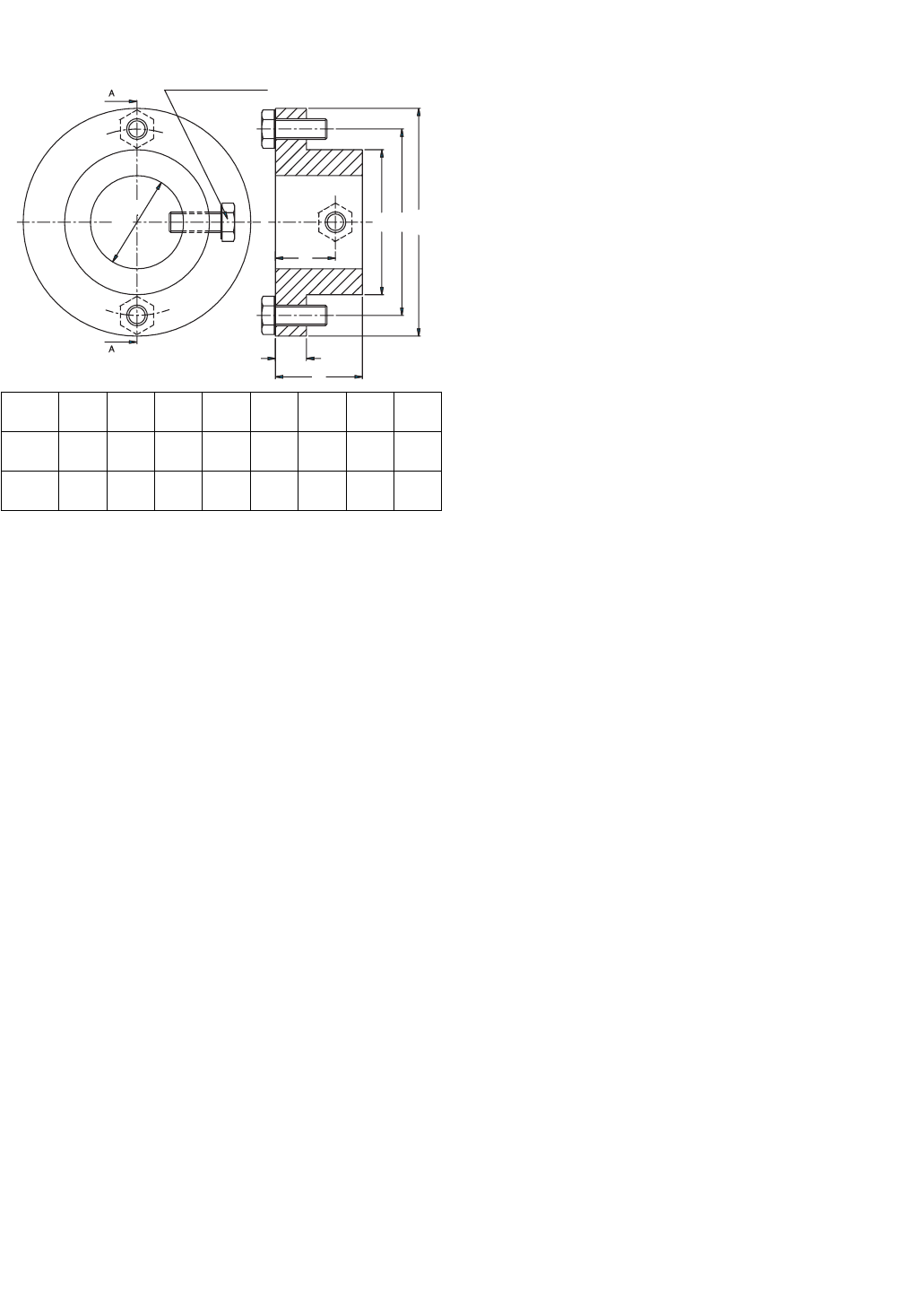
CHAM. (TYP.)
B
A
MODEL
160
250
502
400
630
A
B
DIA.
NO.
PART
3 1/2
4 3/4"
2.441"
811.042.01
811.042.01
2.433"
1.555"
1.547"
Fig. 2 - Disassembly of Bearing Module
Fig. 3 - Bearing and Shaft Seal Removal Tool
Press
Needle bearing
Shaft
seal
Work plate
End plate
Bearing and shaft
seal removing
tool (see Fig. 8)
9

7.2
Bearings, Bearing Sleeves, Shaft Seals
If the bearing and seal sleeves (Ref. 18) have been
removed the new bearing sleeves need to be preheat-
ed prior to installation. Preheat sleeves in an oil bath
(approximately 250°F), an induction bearing heater or a
hot plate. Install the sleeves on the shaft so they touch
the shoulder of the rotor. Use the bearing sleeve instal-
lation tool (see Fig. 5) to position the sleeve.
Bearings should be installed using an arbor press and
special tool (see Fig. 6) to insure proper depth of bear-
ings . Using a hammer to install the bearings may dam-
age them. Other special tools are also required for
installation of the bearings and shaft seals (see Fig. 7).
D
B
A
C
1" X 45
O
D 3.150 5.906
C 1.200 1.783
B 1.575 2.047
A 3.740 6.496
0160/0250 0400/0502/0630
Dimensions are in inches
Fig. 5 - Bearing Installation Tool
Fig. 6 - Bearing and Shaft Seal Installation Tools
Fig. 7 - Shaft Seal Installation Tool
10
Fig. 4 - Exhaust Valve Assembly

The shaft seal (Ref. 35) should be installed with the
spring side towards the bearing. Verify that the shaft
seal is equipped with a spring on the inner lip. Prior to
installing the shaft seal in the endplate, put a drop of
Loctite No. 242 on the outside circumference of the
shaft seal. Be sure that the correct seals (Buna or
Viton) are installed.
7.3 Pump Module for Regular Overhaul
For the 0160/0250 pumps only, place the pump cylinder
(Ref. 1) in a vise (see Fig. 8). Position of the assembly
depends on whether you have an older style, or a
newer style of pump.
For the 0400/502/0630 pumps only, place the cylinder
on a work bench with the inlet port facing you and the
exhaust port facing down (see Fig. 9). Place two small
pieces of 2x4s under the cylinder so that it will raise the
cylinder enough to be able to slip the endplates on later.
The cleaning procedure of the rotor in Section 5.0 must
be followed prior to installation of the rotor. With the
inlet of the cylinder (Ref. 1) facing you, the left will be
the motor side. Slide the rotor (less vanes) inside the
cylinder with the longer rotor shaft towards the motor
side. Take care not to damage the cylinder or rotor.
Place the vanes inside the rotor slots with the relief
grooves, if any, on the trailing side (see Fig. 9).
Endplates (Ref. 25 and 26) should have been prepared
as indicated in Section 6.1. If only a normal overhaul
was performed and the rotor, endplates or cylinder were
not replaced, the following procedure should be fol-
lowed. Carefully insert the endplates over the shaft.
The endplate with the fan cover mounting bosses (Ref.
26) goes on the fan side of the module (see Fig. 10).
Care must be taken not to damage the shaft seal when
sliding over the bearing sleeve. Preferably, one should
use a special shaft seal installation sleeve (see Fig. 11).
Note: Models 0160/0250-132/128, 0400/502/0630-
212/218, use a large O-ring (Ref. 50) to seal the end-
plate on the cylinder. Models 0160/0250-112/118 use a
paper gasket material to seal the endplate to the cylin-
der. On pumps with paper gaskets, use the same quan-
tity and thickness on each side as were removed during
disassembly. Cases in which it is not possible to iden-
tify what gaskets were removed, use one thick (0.1mm-
.0039”) gasket on each side. Place the paper gasket
over the studs on the pump cylinder. With endplates in
place, install the taper pins (Ref. 60) hand-tight, and
loosely tighten the nuts and bolts of the endplates by
hand. Tap the taper pins into the endplate and cylinder
with a hammer until a solid sound is heard. Now pro-
ceed to tighten all nuts and bolts with a wrench.
Fig. 8 - Position of Cylinder for RA/RC 0160
Fig. 9 - Position of Cylinder for RA/RC 0400,
0502 and 0630
Motor side
O-ring
Fan side
End plate
Inlet
Exhaust
Fig. 10 - Endplate Installation
D 3.150 5.906
C 1.378-1.374 2.047-2.043
B 1.299 1.732
A 1.205-1.201 1.780-1.772
0160/0250 0400/0502/0630
Dimensions are in inches
Fig. 11 - Shaft Seal Installation Sleeve
Shaft seal installation
sleeve (see Fig. 14)
11
o
o
Taper pin holes
parallel to floor

It will now be necessary to check for proper axial and
radial clearances. The axial clearance is checked by
installing a dial indicator on one end of the shaft (see
Fig. 12). Pull the opposite end of the shaft as far as it
will pull away from the dial indicator. Set the indicator
at zero (0). Push the shaft toward the dial indicator as
far as it will push. The reading on the dial indicator will
be your axial clearance. The recommended axial clear-
ances are shown in the chart located near the back of
this manual (see page 21).
Check the radial clearances (see Fig. 13) by inserting a
feeler gauge blade into the inlet of the pump in the
direction of the smallest clearance between rotor and
cylinder. Check the radial clearance in three (3) loca-
tions along the rotor. The recommended radial clear-
ances are shown in the chart located near the back of
this manual (see page 21).
If clearances check out okay, one may proceed to
assemble the pump. If clearances do not correspond to
what they should be or if a new rotor, endplates or cylin-
der were used, one will have to use the procedure men-
tioned for Assembly of Module if the Rotor,
Endplates or Cylinder had to be replaced.
Note: On Models 0160/0250-112/118, the axial clear-
ances can be changed by either placing another paper
gasket between the cylinder and endplate to increase
the axial clearance or using a thinner gasket to
decrease the axial clearance. There should always be
at least one (1) gasket between the cylinder and end-
plate. On models with O-rings, the axial clearance is
preset and cannot be changed, but if the rotor sits in the
cylinder uneven (meaning cocked), it will give a false
axial clearance reading. The rotor needs to be aligned
straight with respect to the cylinder to be able to get the
necessary axial clearance.
Assembly of Module if the Rotor, Endplates,
or Cylinder had to be Replaced:
Make sure that all parts have been wiped clean of oil
and that flat surfaces have been honed with smooth
sand stone prior to assembly.
With the cylinder (Ref. 1) in the vise (0160/0250 only)
positioned as indicated in Figs. 8 or 9, measure the
length of the cylinder and the length of the rotor (Ref.
15) with a micrometer or other available measuring
device, if at all possible. These measurements can
help in determining axial clearance in the assembled
stage. If the above measured axial clearance is not
obtained after the endplates are assembled, it gives an
indication that the rotor is cocked inside the cylinder
housing. If a micrometer or other measuring device is
not available, use the recommended distances men-
tioned in the clearance chart.
Place the rotor (Ref. 15) carefully inside the pump cylin-
der (Ref. 1) with the long shaft end on the motor side.
With the inlet of the cylinder facing you, the motor side
is to your left.
Place vanes inside the rotor slots. Check the vanes to
be sure they do not extend beyond the length of the
rotor; if they are too long, sand down the ends with a
medium grade sand paper (see Fig. 9). Make sure that
the rotor is not resting on one of its slots when assem-
bling.
Insert two .07mm (0.0027 in.) feeler gauge blades for
0160/0250 pumps and .08mm (0.0031 in.) for
0400/502/0630 pumps through the inlet, over the top
and underneath the rotor to the far left and far right
position of the cylinder (see Figure 13). The rotor
should be sitting on the feeler blades. The feeler gauge
shown in Fig. 13 is only for checking radial clearances
after assembly.
Slide motor side endplate (Ref. 25) onto the rotor shaft
using a seal installation tool (see Fig. 11) and install cap
screws hand tight. Slide fan side endplate (Ref. 26) on
rotor shaft and hand-tighten bolts.
Install the rotor pulling tool (see Fig. 14) onto the fan
side rotor shaft. Use the puller to pull the rotor toward
the fan side endplate squaring the end of the rotor to
the face of the endplate. Rotate the rotor and endplate
(within the endplate mounting holes) until the two taper
pins can be inserted into the cylinder. Push (by hand)
the pins into the cylinder, providing a partial alignment
intended to return the assembly near its original posi-
tion. If the cylinder was machined, the taper pin holes
will be slightly off.
Fig. 12 - Axial Clearance Measuring
Fig. 13 - Checking Radial Clearance
12
Note: A new cylinder will not have taper pin holes. A
new endplate will only have pilot holes.
When new parts are used the rotor and fan side
endplate should be rocked back and forth (within the
clearance of the mounting holes) until the bolts are cen-
tered within the holes. Once the endplate is centered,
tighten the mounting bolts.
When the existing parts are used but the
cylinder has been machined proceed with the
loosely inserted taper pin method. After tightening the
fan side endplate mounting bolts, proceed to the motor
side endplate. Center the motor side endplate by
loosely inserting the taper pins or by the "feel" method
of working it back and forth. Tighten the motor side
endplate mounting bolts.
Loosen the rotor pulling tool, but leave the pulling tool
on the shaft since it will assist you in turning the rotor.
Remove the feeler blades by turning the rotor from the
fan side counterclockwise (see Fig. 13). Check the tips
of the feeler gauge blades to make sure nothing has
broken off. It will be necessary to remove the broken
piece, and start over if a piece of the feeler gauge blade
has broken off.
Attach a dial indicator on the motor side rotor shaft as
indicated in Fig. 12 to check axial clearance. Do not
change anything until the radial clearance is checked.
Follow the same procedures as mentioned previously.
If the resistance of the feeler blades between the rotor
and the cylinder feel tighter on one end of the cylinder
than the other, use a hammer to tape the endplate on
the tighter side slightly upward until an even resistance
of the feeler blade can be measured on both ends of the
rotor. A difference of .02mm (.0008 inch) radial clear-
ance can be tolerated between the fan side and the
motor side of the rotor as long as the minimum clear-
ance is maintained. If the rotor is square with the end-
plates, but the rotor to cylinder clearance between the
motor side and fan side differs more than .02mm, the
cylinder must be remachined. The rotor should turn
freely after the removal of the feeler blades.
The axial clearance should be checked again and if the
readings are still not within the correct tolerances, it is
recommended to start over again. Both the axial and
radial clearances have to be within the recommended
tolerances in order to proceed. A reworked cylinder can
occasionally be machined with a taper or irregularity in
the bore. If a bore is suspected to be irregular, it is all
the more important to make sure the end of the rotor is
parallel with the inside face of the endplates.
After clearances are correct, proceed to prepare to drill
out the taper pin holes by closing the inlet with a clean
rag and covering the bearing seals with a rag. Plug any
open holes in the endplates. Look into the taper pin
holes in the endplates with a flashlight to see how close
the old taper pin holes are from the endplate, and line
up the taper pin holes in the cylinder. If the holes are
only slightly off, redrill the holes with the same size
tapered drill as was used originally. If the holes do not
line up very close, it will be necessary to drill out the
holes to the next larger size and use taper pins the next
larger size. To prevent from drilling too deeply into the
pumping module, it is recommended to measure the
depth of the old holes. Make yourself a mark with tape
on your drill bit to assure the proper depth. Use a
tapered reamer to ream the holes out after drilling.
These tools are available from Busch, Inc.
Put a little bit of "Never Seize" on the new taper pins
and insert them into the endplates. Lightly tap them
with a hammer to insure proper seating.
Squirt oil into the pump module and turn rotor by hand
to lubricate vanes and rotor slots well. The pump can
now be reassembled.
7.4 Pump Assembly
When the pump module was separated from the
exhaust box for repair, follow these reassembly instruc-
tions:
Reconnect exhaust valves (Ref. 159) on the pumping
module for 112/132/212 pumps. See Section 7.1.
Reconnect the pumping module to the exhaust box
(Ref. 75) after placing the proper gasket (Ref. 185) in
between the module and the exhaust box.
A
F
E
C
B
H
HEX HEAD CAP SCREW
TYP (3) PLACES - G
D
Pump A B C D E F G H
160/250 90 100 15
30.2-
30.5
50 72
M8x
30
30
400/502
630
110 42 15
45.2-
45.3
70 90
M10x
25
29
Fig. 14 - Rotor Pulling Tool
Dimensions are in mm
13

Attach all oil lines leading from the exhaust box to the
module endplates (Ref. 231/232), except the oil return
line (Ref. 290).
The oil lines on Model 0630 connect to the radiator and
are then distributed to the endplates.
Reconnect the oil cooling coil (Ref. 240) (not applicable
on Model 0502/0630).
Make sure all hydraulic fittings are good and tight.
Attach motor mounting bracket (Ref. 300) to the motor
side endplate (Ref. 25).
Prior to Bowex "gear type" coupling installation (Ref.
310), check serrated edges of the coupling halves for
burrs that would prohibit the coupling insert from sliding
freely. Install the pump side coupling half (Ref. 310)
and tighten set screws. A distance of 4mm must be
maintained between the pump coupling half and the
motor coupling half when the pump and motor are con-
nected (see Fig. 15).
Measure the distance from the end of the pump cou-
pling half to the face surface of the motor mounting
bracket, which is indicated in Figure 15 as Distance "A".
Subtract 4mm from Distance "A". This measurement is
the distance from the motor coupling, which is indicated
in Figure 15 as Distance "B". This is for Bowex cou-
plings only. The most current coupling used is a
"Wood’s" type coupling. This coupling when properly
adjusted, will allow the sleeve to move 1mm (clearance)
back and forth from flange to flange. The pump and
motor come from the factory with a set of spacers that
automatically set the correct sleeve clearance. If these
spacers are reassembled the same as originally
installed, the clearance will be correct. Place a locking
disc on the end of the motor shaft to hold coupling and
cooling fan in place. Coupling set screws cannot be
tightened due to the cooling fan; that is why a locking
disc is used. For the 0502/0630 pump, mount the pump
coupling half in such a way so that the coupling half pro-
trudes outward from the rotor shaft by 10mm. The
motor coupling half is mounted flush against the motor
shaft and is held in place by two set screws.
Note: Make sure to Loctite set screws in place for all
couplings and motor fans to prevent movement.
Install the gas ballast (Ref. 440) on the fan side end-
plate (Ref. 26) on 112, 132, and 212 models only.
Install the fan side cooling fan (Ref. 321) flush against
the rotor shaft bearing sleeve (Ref. 18) on the
0160/0250 models. Tighten set screws on the fan
mounting boss. On the 0400 models, insert a distance
ring (Ref. 320), then slip on the fan (Ref. 321) and tight-
en the set screw. Attach the fan cover (Ref. 340) on the
fan side endplate (Ref. 26). For the 0502/0630 pumps
slip on the distance ring (Ref. 320). Attach the metal
shroud (Ref. 350) to the endplate (Ref. 26). Attach the
fan (Ref. 321) and tighten the set screw. Place the lock-
ing disc (Ref. 327) on the shaft end. Attach the radiator
side metal shroud (Ref. 351) with the fan cover guard
(Ref. 352) and distance bolts (Ref. 355), in place.
Reconnect the radiator (Ref. 241) with the radiator
bracket on the metal shroud. Reconnect all the oil lines
at the same time.
Squirt Busch R530 oil into the pump module and turn
the rotor by hand to lubricate the vanes and rotor slots.
Attach the inlet housing (Ref. 260 and 250) to the mod-
ule using a gasket (Ref. 255) on Models 0160/0250-
112/118 and 0400/0502/0630-212/218, or an O-ring
(Ref. 80) on Models 0160/0250-132/138 or new type
0400/0502/0630-212/218. Make sure the anti-suck-
back valve is functioning and that the O-ring (Ref. 253)
is in good condition.
Reconnect the oil return line (Ref. 290) or non-return
valve (Ref. 275). Do not over-tighten.
Connect the motor (Ref. 400) to the motor mounting
bracket (Ref. 300) with the fan (Ref. 322) attached to
the motor shaft for pump Models 0160/0250-112/118,
132, 138 and 0400-212/218. The 0502/0630 model
does not use this fan. Make sure the motor coupling
half is on the motor shaft and the coupling insert has
been placed on the module side coupling half. See
Figure 15 for proper coupling insert play.
Fill the pump to the proper level on the oil sight glasses
with Busch 500 Series oil.
Connect the proper power supply to either the motor
conduit box or the pump manual starter. Be sure all the
connections are tight.
Fig. 15 - Coupling Adjustment
CAUTION: The rotor in this pump is free
floating. If the coupling is too tight it will,
when hot, force the rotor into the fan side
endplate causing damage to the pump.
14

Jog the pump to determine the correct rotation of the
pump. The pump rotation should be counterclockwise
when looking at the motor fan from the motor end. If the
rotation is incorrect, change any two of the three lead
wires and check the rotation again.
8.0 CHANGING FROM RA TO RC MODEL
If a pump needs to be changed to either a RA or a RC
pump, it can easily be done by following the instruction
below.
Drain the oil.
Remove the oil non-return valve (Ref. 275) and copper
washer (Ref. 276) from the end of the exhaust box.
Remove the plug (Ref. 270) and copper washer (Ref.
271) from the inlet flange.
The gas ballast valve (Ref. 440) can be removed if
there is no chance of water vapor condensing in the
pump module. If water condensation could be a prob-
lem, it is recommended that the gas ballast is left in
place. The gas ballast can easily be removed on
0160/0250 and 0400 pumps by removing the fan cover
(Ref. 340) and the fan (Ref. 321). After removing the
gas ballast, be sure to close the opening with a plug
(Ref. 46) and a copper washer (Ref. 47). The hex head
screws (Ref. 441/442), which hold the gas ballast
bracket to the exhaust box, can be reinstalled by plac-
ing some Loctite and a copper washer on the screw. To
remove the gas ballast from a 0502/0630 pump, it is
recommended to lift the pump in the air and remove the
hydraulic fitting without removing the radiator. It is very
tight to get in there, but it can be done.
If the vacuum requirements are only in the 15 Torr
range, it is recommended to remove the exhaust valves
(Ref. 159) on the 132 and 212 models. On Model 112,
the valves can be left in, since it would take a complete
disassembly of the pump to remove them. See Section
4.2 for removal of exhaust valves.
Connect the oil return line (Ref. 290) with the elbow fit-
ting (Ref. 291) to the inlet flange where the 1/8" plug
and washer (Ref. 270/271) were removed. The elbow
fitting needs to be screwed into the inlet before attach-
ing the oil line to it (use some Loctite 242).
Connect the banjo fitting (Ref. 286) to the other end of
the oil line. Make sure that the lipped end of the banjo
fitting is facing the exhaust box.
Do not over-tighten the banjo screw (Ref. 285) or the
threads inside the aluminum exhaust box will be
stripped.
To change from a RC 118, 138, 218 to a RA 112, 132,
212, use the same instruction in the reverse order. You
might not be able to obtain an end vacuum of 29.98 in
Hg. at blank-off. Please consult the factory for further
information.
8.1 Difference between RA and RC Pumps
The RC model pumps 118/138/218 can run continuous-
ly because any oil buildup in the exhaust filter area of
the exhaust box is constantly being sucked through the
oil return line into the module through the inlet flange.
Since this oil return line will also carry some atmos-
pheric air, it reduces the vacuum level at blank-off to
about 15 Torr or 29.3 in. Hg.
On RA model pumps an oil non-return valve is used. It
is a ball check valve. When the pump is running, this
check valve will close automatically. When the pump is
not in operation, the check valve will open up and allow
the oil from the exhaust filter area to drain into the pump
oil sump.
Older RA pumps had to be shut down periodically to
allow any oil buildup to drain back into the sump. If this
was not done, the oil would collect in the exhaust filter
area to a point where it would be blown out of the
exhaust port; the pumping module was also being
deprived of oil which could result in vane damage.
Since there was no atmospheric air being introduced at
the inlet through an oil return line, the pump was able to
run at a blank-off pressure of .5 Torr or 29.9 in. Hg.
Newer model RA 0400/0502/0630 pumps are
provided with an oil level float valve as described
in Section 2.2, but an older existing pump in the field
can be modified to have this oil float valve assembly by
ordering a float valve kit Busch P/N 0946.529.715.
Contact the Service Department of Busch, Inc. in
Virginia Beach is you wish to add this feature to an
older pump in the field or if you are unsure whether you
pump has this feature already.
9.0 OIL LEVEL SWITCH INSTALLATION
Contact the factory.
15

Remedy:
Replace the automotive-type oil filter, exchange the oil,
if necessary, and refill with fresh oil.
Possible Cause:
The inlet anti-suck-back valve plate (Ref. 251) is stuck
in the closed or partially open position due to contami-
nation.
Remedy:
Disassemble the inlet valve and screen. Clean as
required.
Possible Cause:
Oil tubing fittings are loose and leaking. Oil return line
broken on RC model.
Remedy:
Replace or retighten oil fittings or oil tubing. Replace
only with the same size tubing.
Possible Cause:
Shaft seal leaking.
Remedy:
Replace the shaft seal following disassembly and
assembly instruction. Check the shaft seal. It should
have a spring installed inside and around the shaft seal-
ing lip. Check and replace the shaft seal/bearing sleeve
if worn.
Possible Cause:
The exhaust valve (Ref. 159) is not properly seated or
is partially stuck open (RA models only).
Remedy:
Follow the disassembly and assembly instructions or
contact the nearest Busch Factory Service Center.
Possible Cause:
Vanes are stuck in rotor or otherwise damaged.
Remedy:
Free vanes or replace with new ones following disas-
sembly and assembly instructions or contact the near-
est Busch Factory Service Center.
10.0 TROUBLE SHOOTING
10.1 Trouble
The pump does not reach "blank-off" pres-
sure which is the lowest absolute pressure
(best vacuum) when running with the inlet
covered via a blank flange or a valve; or
pump takes too long to evacuate the system.
The blank-off pressure can be measured by
using a good quality capsule gauge.
Possible Cause:
Contaminated oil is by far the most common cause of
not reaching the ultimate pressure.
Remedy:
Shut off the pump after operating temperature has been
reached, drain the warm oil from the pump, and
exchange automotive type oil filter, if necessary. Flush
and fill pump with new oil and take a new blank-off
measurement after the operating temperature is
reached (at least 20-30 minutes).
Possible Cause:
Vacuum system or vacuum piping is not leak-tight.
Remedy:
Check hose and pipe connections for possible leaks.
Possible Cause:
Wire mesh inlet screen plugged (Ref. 261).
Remedy:
Clean the wire mesh inlet screen. Install an inlet filter if
problem repeats frequently.
Possible Cause:
No oil or not enough oil in oil reservoir.
Remedy:
Shut off the pump, add the necessary oil, or oil seems
contaminated, drain the balance of the oil from the
pump, exchange the automotive type oil filter, and refill
with fresh oil. Flush if necessary.
Possible Cause:
The automotive type oil filter is dirty or clogged (where
applicable).
16

Possible Cause:
Radial clearance between the rotor and cylinders is no
longer adequate.
Remedy:
Follow disassembly and assembly instructions on
resetting radial clearance correctly.
Possible Cause:
Internal parts worn or damaged.
Remedy:
Follow the disassembly and assembly instructions and
replace worn or damaged parts.
10.2 Trouble
The pump will not start.
Possible Cause:
The motor does not have proper supply voltage or is
overloaded; motor starter overload settings are too low
or wrong setting, fuses are burned; wire size is too
small or too long, causing a voltage drop at the pump.
Remedy:
Check correct supply voltage; check the overload set-
tings in the motor starter for size and setting according
to the motor nameplate data; check fuses; install the
proper size wire. If the ambient temperature is high,
use the next larger size overloads or adjust the setting
5% above the nominal motor nameplate value.
Possible Cause:
Pump or motor is blocked.
Remedy:
Remove the fan cover and try to turn the pump and
motor by hand. If frozen, remove the motor from the
pump and check the motor and pump separately. If the
pump is frozen, disassemble completely and remove
foreign objects in the pump or replace broken vanes.
10.3 Trouble
Pump starts, but labors and draws a very
high current.
Possible Cause:
Oil is too heavy (viscosity too high) or the ambient tem-
perature is below 5C° (41°F).
Remedy:
Change to R580 vacuum oil if very cold, or warm up the
pump oil before filling.
Possible Cause:
Pump runs in the wrong rotation.
Remedy:
Check for correct rotation which is counterclockwise
when looking at the motor from the motor's fan side.
Possible Cause:
Pump is overfilled with oil, or wrong kind of oil is used.
Remedy:
Correct oil level and quality, and use only Busch vacu-
um oil.
Possible Cause:
Exhaust filters in exhaust are clogged and burned black
with pump oil.
Remedy:
Replace exhaust filters; maintain proper oil condition,
oil level and use Busch R500 Series vacuum oil.
Possible Cause:
Exhaust filter is clogged due to process material.
Remedy:
Contact factory for recommendation or proper filter car-
tridge.
Possible Cause:
Loose connection in motor terminal box, not all motor
coils are properly connected. Motor operates on two
phases only.
Remedy:
Check motor wiring diagram for proper hook-up, espe-
cially on motors with six internal motor windings, tight-
en and/or replace loose connections.
Possible Cause:
Foreign particle in pump; vanes broken; bearing seiz-
ing.
17

Remedy:
Follow disassembly and assembly instructions and
remove foreign parts; replace vanes and bearings.
10.4 Trouble
Pump smokes at the exhaust side or expels
oil droplets from the exhaust.
Possible Cause:
Exhaust filter not properly seated with O-ring (Ref. 121)
in filter base or filter material is cracked.
Remedy:
Check condition and check for proper seating of
exhaust filters. Replace if necessary. Also, check filter
spring clips for tightness.
Possible Cause:
Exhaust filter clogged with foreign particles.
Remedy:
Replace the exhaust filter.
Possible Cause:
Oil non-return valve (Ref. 275) not working properly.
Proper function is that when blowing compressed air
into the check valve, it should close. When applying
vacuum on it, the check valve should open.
Remedy:
Free or replace the oil return check valve.
Possible Cause:
If an older RA Series vacuum pump run continuously
over 8 hours without ever being shut down, it may be
possible that oil accumulates behind the exhaust box
cover (Ref. 140) to the extent that oil is blown out of the
exhaust with the exhaust gas.
Remedy:
Shut pump down during break periods. Check that oil
return valve (Ref. 275) is free and drains oil back into
the exhaust box oil sump when the RA pump is
stopped.
Possible Cause: Oil return line (Ref. 290) on RC
pumps is clogged or broken.
Remedy:
Free the clogged line, replace the broken line, but only
with the proper size, and check that the oil is pumped
out of the oil sump while the vacuum pump is operating.
Note: An oil filling plug with pressure gauge is supplied
as a standard item for all R 5 Series pumps so that the
pressure in front of the exhaust filters can be monitored.
The green field indicates that the filters are still effec-
tive. Any back pressure in the red field requires imme-
diate change of the exhaust filter (Ref. 120).
10.5 Trouble
Pump runs very noisy.
Possible Cause:
Coupling insert is worn.
Remedy:
Replace coupling insert motor/pump coupling.
Possible Cause:
Bearing noise.
Remedy:
Follow disassembly/assembly instructions outlined in
this manual and the replace bearings.
Possible Cause:
Vanes stuck.
Remedy: Follow disassembly/assembly instruction;
replace vanes. Use R500 Series vacuum oil.
10.6 Trouble
Pump runs very hot.
Note: The oil temperature with a closed inlet should be
approximately 185-225°F depending on pump type. At
24 in. Hg, the oil in the pump can go above 225°F.
These values are taken at an ambient temperature of
68°F. The maximum recommended ambient operating
temperature for an R 5 is 100°F on a continuous basis.
When it is necessary to operate a pump in ambient tem-
peratures above this limit, careful oil monitoring and/or
optional water cooling is necessary. Contact the facto-
ry at Virginia Beach for details.
18

Possible Cause:
Not enough air ventilation to the pump.
Remedy:
Clean motor and pump air grills. Do not install pump in
enclosed cabinet unless sufficient amount of fresh air is
supplied to pump. On pumps with oil cooling coils,
clean outside fin assembly. Bring ambient air tempera-
ture down.
Possible Cause:
The automotive type oil filter (Ref. 100) is clogged and
pump does not receive enough oil.
Remedy:
Change automotive oil filter.
Possible Cause:
Not enough oil in oil reservoir or badly burned oil is
used for pump lubrication.
Remedy:
Flush (see Section 3.1.4) and refill only with Busch rec-
ommended oil. Increase oil change intervals.
Note:
On some high temperature applications, it may be nec-
essary to change to a high temperature oil such as
R590 or R570. Contact the factory for recommenda-
tions.
10.7 Trouble
Pump is seized.
Possible Cause:
Pump was operated without oil and vanes broke.
Remedy:
Disassembly and exchange vanes per instructions.
Possible Cause:
Pump was operated for an extended period of time in
the wrong rotation.
Possible Cause:
Liquid carryover into pump cylinder broke the vanes
while pump was running or oil broke the vanes on start-
up.
Remedy:
Install condensate trap on the inlet of the pump. Or,
pump was overfilled with oil in oil reservoir. Follow oil
filling procedure (see Section 1.1) and do not overfill.
Or, built-in anti-suck-back valve (Ref. 250 through 255)
is leaking while pump was shut down and vacuum was
left in manifold. Clean valve seat and check that anti-
suck-back valve holds vacuum on inlet when pump is
shut down. Or, two pumps or a receiver is on the same
main line. Install a manual or automatic operated valve
in front of each pump.
10.8 Trouble
Automotive-type oil filter (Ref. 100) does not
get warm within two to five minutes when
cold pump is started.
Possible Cause:
Automotive-type oil filter is clogged.
Remedy:
Replace oil filter and exchange oil.
Possible Cause:
Wrong automotive-type filter is used and/or oil lines
leading to pump are clogged.
Remedy:
Use only the proper Busch genuine oil filter and blow
lines free
.
19

11.0 LIMITED STANDARD WARRANTY
Busch, Inc. warrants that all products furnished by it are
free from defects in material and workmanship at the
time of shipment for a period of 18 months from the
date of shipment, or 12 months from the date of instal-
lation, whichever occurs first. Claims must be made
during that period and are limited to the replacement or
repair of parts claimed to be defective.
In the case of components purchased by Busch, Inc.,
such as starters, controls, mechanical seals, motors,
couplings, etc., the warranty of that manufacturer will be
extended to the purchaser in lieu of any warranty by
Busch, Inc. The replacement of wear items including,
but not limited to, seals, bearings, couplings, exhaust
cover gaskets, oil drain plugs, oil fill plugs etc., made in
connection with normal service are not covered by this
Warranty.
The Limited Standard Warranty is valid only when the
product has been properly installed, used in a normal
manner, and serviced according to the operating man-
ual. This warranty shall not extend to products that
have been misused, neglected, altered, or repaired
without factory authorization during the warranty period.
We highly recommend the use of Busch oils and parts
to achieve documented performance and efficient oper-
ation. The use of oils or parts other than Busch could
limit the life expectancy of the equipment and could void
any warranties if they are the cause of any damage.
Operating conditions beyond our control such as
20
improper voltage or water pressure, excessive ambient
temperatures, or other conditions that would affect the
performance or life of the product will also cause the
warranty to become void.
Permission to return parts for warranty repair must be
obtained, and all returns must be prepaid to the factory.
If, after examination, the product or part is found to be
defective, it will be repaired or replaced on a no-charge
basis and returned, FOB the factory. If it is determined
that the Warranty has not been breached by Busch,
Inc., then the usual charges for repair or replacement
will be made, FOB the factory. Parts or products that
are obsolete or those made to special order are not
returnable.
This Limited Standard Warranty applies only to the
above and is for the period set forth. Busch, Inc.'s max-
imum liability shall not, in any case, exceed the contract
price for the product, part, or component claimed to be
defective; and Busch, Inc. assumes no liability for any
special, indirect, or consequential damages arising
from defective equipment.
THERE ARE NO WARRANTIES IMPLIED OR
EXPRESSED THAT EXTEND BEYOND THOSE
CONTAINED IN THIS LIMITED STANDARD
WARRANTY.
Note: For extended warranties on your new equip-
ment contact Busch, Inc. Headquarters at 1-800-USA-
PUMP.

* Without gas ballast
TYPE
Length of
Cylinder
Rotor Cylinder Vanes Axial Radial
Bearings
Needle
160 140
+0.0
-0.025
+0.070
+0.050
-0.04
-0.08
max 0.095
min 0.050
0.03
0.07
0.020-
0.040
250 220
+0.0
-0.029
+0.100
+0.080
-0.12
-0.15
max 0.129
min 0.080
0.03
0.07
0.020-
0.040
400 265
+0.0
-0.032
+0.190
+0.165
-).18
-0.21
max 0.222
min 0.165
0.10
0.06
0.050-
0.035
502 330.6
+0.0
-0.032
+0.200
+0.175
-0.20
-0.24
max 0.232
min 0.175
0.10
0.06
0.050-
0.035
630 400
+0.0
-0.036
+0.245
+0.215
-0.20
-0.24
max 0.281
min 0.215
0.06
0.10
0.035-
0.050
Clearance Chart
After assembling the endplates, a reduction of .01mm of axial clearance is allowed.
Clearances are listed in millimeters.
Model 0160 0250 0400 0502 0630
Nominal pumping
speed
ACFM 115 170 305 375 455
Free air displacement CFM 117 180 330 413 490
Maximum sound level 1
meter from pump
dBA 79 81 83 84 85
Motor size for 3 phase HP 7.5 10 15 20 25
Motor rotational speed rpm 1750 1750 1150 1150 1150
Approximate oil capacity qt. 7 7 14 16 16
Inlet connection - NPT inch 2 2 3 3 3
End vacuum (RC) Torr 15 15 15 15 15
End vacuum (RA)* Torr 0.5 0.5 0.5 0.5 0.5
Approximate weight pounds 416 460 1152 1316 1525
Technical Data
21
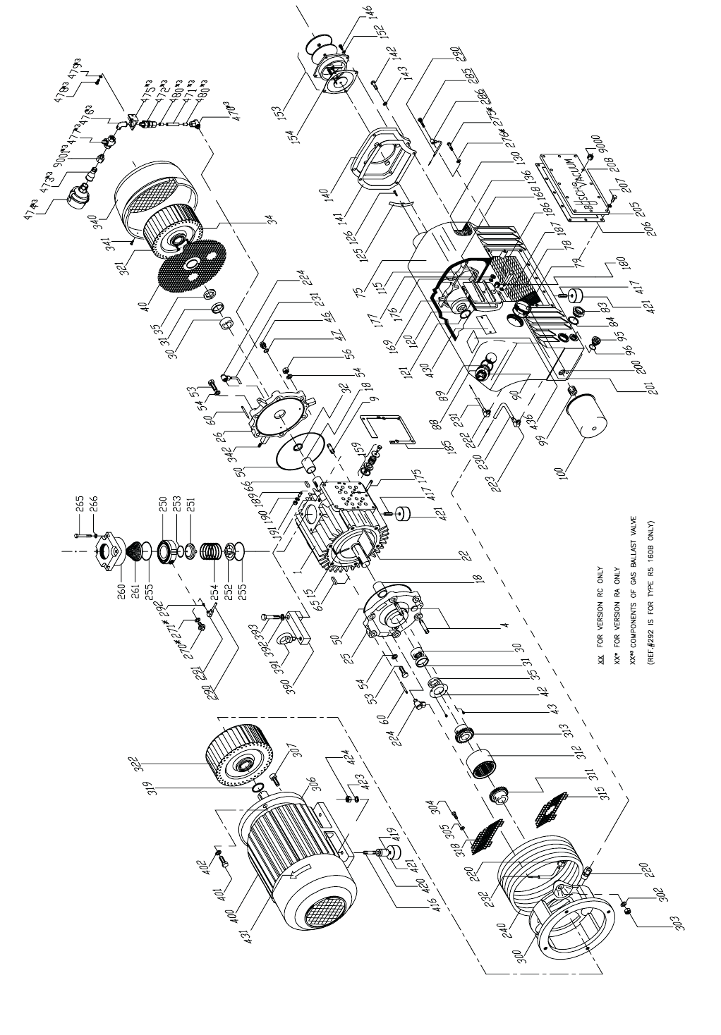
Fig. 16 - Illustration of R 5 0160 Vacuum Pump
22

Parts List for R 5 0160
Ref Description
001 Cylinder
004 Stud
009 Stud
015 Rotor
018 Bearing sleeve
022 Vane
025 Motor side endplate
026 Opp. M.S. endplate
030 Needle bearing
031 Endplate spacer
032 Pump spacer
034 Slotted chs. hd. cap screw
035 Shaft seal
040 Protective screen
042 Shaft seal retaining plate
043 Hex head cap screw
046 Hex head plug
047 Copper ring gasket
050 O-ring
053 Hex head cap screw
054 Lockwasher
056 Hex head cap nut
060 Tapered pin
065 Shaft key
066 Shaft key
075 Exhaust box
078 Sheet metal baffle
079 Demister pad
083 Oil sight glass
084 Ring gasket
088 Oil fill plug
089 Oil fill plug gasket
090 Pressure gauge
095 Oil drain plug
096 O-ring
099 Nipple
100 Auto-type oil filter
115 Filter bracket
120 Exhaust filter
121 O-ring
125 Filter spring assembly
126 Socket head cap screw
130 Baffle strainer
136 Baffle strainer frame
140 Exhaust cover plate
141 Cover plate gasket
142 Hex head cap screw
143 Lockwasher
146 Hex head cap screw
152 Lockwasher
153 Exhaust silencer
154 Gasket
159 Exhaust valve
168 O-ring
169 Exh. valve cover plate
175 Stud
Ref Description
322 Motor side fan
340 Fan Cover
341 Sheet metal screw
342 Plastic insert
390 Eyebolt adapter
391 Eyebolt
392 Lockwasher
393 Hex head cap screw
400 Motor
401 Hex head cap screw
402 Lockwasher
416 Stud
417 Slotted set screw
419 Foot spacer
420 Flat washer
421 Rubber foot
423 Washer
424 Hex head cap nut
430 Nameplate
431 Arrow label
436 Maintenance label
470 Hydraulic fitting
471 Teflon tubing
472 Check valve
473 Bell reducer
474 Gas ballast filter
475 Gas ballast valve bracket
476 Elbow fitting
477 Pet cock valve
478 Hex head cap screw
479 Lockwasher
480 Oil tube insert
9000 Steel socket plug
9001 Hydraulic adapter
Ref Description
176 Lockwasher
177 Hex head nut
180 Plug
185 Gasket
186 Hex head cap screw
187 Lockwasher
189 Stud
190 Lockwasher
191 Hex head nut
200 Drum exhaust box plug
201 O-ring
205 Cover side plate
206 Gasket
207 Hex head cap screw
208 Lockwasher
220 Hydraulic fitting
222 Hydraulic fitting
223 Hydraulic fitting
224 Hydraulic fitting
230 Oil tubing
231 Oil tubing
232 Oil tubing
240 Cooling coil
250 Inlet flange
251 Valve guide
252 Valve plate
253 O-ring
254 Inlet check valve spring
255 O-ring
260 Inlet flange
261 Inlet screen
265 Hex head cap screw
266 Lockwasher
270 Plug
271 Ring gasket
275 Oil return valve
276 Ring gasket
285 Oil recirc. screw
286 Banjo hydraulic fitting
290 Oil return line tubing
291 Hydraulic fitting
292 Carburetor jet
300 Motor mounting bracket
302 Lockwasher
303 Hex shoulder nut
304 Socket hd. machine screw
305 Flat washer
306 C-face adapter flange
307 Socket head screw
311 Motor side coupling half
312 Coupling insert
313 Pump side coupling half
315 Protective screen
318 Protective screen
319 Spacer
321 Pump shaft fan
23

Fig. 17 - Illustration of R 5 0400 Vacuum Pump
24

Parts List for R 5 0400
Ref Description
001 Cylinder
004 Stud
005 Set screw
009 Stud
015 Rotor
018 Bearing sleeve
019 Shaft seal sleeve
022 Vane
025 Motor side endplate
026 Opp. M.S. endplate
030 Needle bearing
035 Shaft seal
040 Protective screen
041 Hex head nut
042 Shaft seal support ring
043 Hex head cap screw
046 Hex head plug
047 Copper ring gasket
050 O-ring
053 Hex head cap screw
054 Lockwasher
056 Hex head cap nut
060 Tapered pin
065 Shaft key
066 Shaft key
075 Exhaust box
078 Sheet metal baffle
079 Demister pad
080 Perforated sheet metal
083 Oil sight glass
084 Ring gasket
088 Oil fill plug
089 Oil fill plug gasket
090 Pressure gauge
095 Oil drain plug
096 O-ring
099 Nipple
100 Auto-type oil filter
105 Cover plate
106 Cover plate gasket
107 Socket head cap screw
108 Lockwasher
115 Filter bracket
116 Filter bracket
120 Exhaust filter
121 O-ring
125 Filter spring assembly
126 Socket head cap screw
130 Baffle strainer
136 Perf. sheet metal screen
137 Hex head cap screw
138 Flat washer
139 Lockwasher
140 Exhaust cover plate
141 Cover plate gasket
142 Hex head cap screw
Ref Description
312 Coupling insert
313 Pump side coupling half
319 Spacer
320 Fan and coupling spacer
321 Pump shaft fan
322 Motor side fan
327 Locking disk
328 Socket head cap screw
329 Lockwasher
340 Fan Cover
341 Sheet metal screw
342 Plastic insert
391 Eyebolt
400 Motor
401 Hex head cap screw
402 Lockwasher
417 Slotted set screw
418 Rubber foot
419 Foot spacer
420 Stud
421 Rubber foot
422 Rubber foot
423 Lockwasher
424 Hex head cap nut
430 Nameplate
431 Arrow label
436 Maintenance label
470 Hydraulic banjo fitting
471 Teflon tubing
472 Check valve
473 Bell reducer
474 Gas ballast filter
475 Gas ballast valve bracket
476 Elbow fitting
477 Pet cock valve
478 Hex head cap screw
479 Lockwasher
480 Oil tube insert
9000 Steel socket plug
9001 Flat washer
9002 Entrance elbow connector
9003 Fenwal temperature switch
9004 Grounding washer
9005 Plain washer
9006 Socket head cap screw
9007 Hex head cap screw
Ref Description
143 Lockwasher
146 Hex head cap screw
153 Cover plate exhaust screen
159 Exhaust valve
168 O-ring
169 Exh. valve cover plate
175 Hex head cap screw
176 Lockwasher
184 Socket head cap screw
185 Cylinder/Exhaust box gasket
186 Hex head cap screw
187 Lockwasher
200 Drum exhaust box plug
201 O-ring
205 Cover side plate
206 Gasket
207 Hex head cap screw
215 Reducing nipple
216 Ring gasket
220 Hydraulic fitting
222 Hydraulic elbow fitting
223 Hydraulic elbow fitting
224 Hydraulic banjo fitting
225 Hydraulic straight fitting
226 Hydraulic banjo fitting
230 Oil tubing
231 Oil tubing
232 Oil tubing
233 Oil tubing
240 Cooling coil
250 Inlet flange
251 Valve plate
252 Valve inlet guide
253 O-ring
254 Inlet check valve spring
255 O-ring
258 Ball, Viton
260 Inlet flange
261 Inlet screen
265 Hex head cap screw
266 Lockwasher
275 Oil return valve
276 Ring gasket
285 Oil recirc. screw
286 Banjo hydraulic fitting
290 Oil return line tubing
291 Hydraulic elbow fitting
297 Screen
298 Slot chs.. head screw
299 Rivet
300 Motor mounting bracket
302 Lockwasher
303 Hex shoulder nut
306 C-face adapter flange
307 Socket head screw
311 Motor side coupling half
25

Fig. 18 - Illustration of R 5 0502/0630 Vacuum Pump
26
R 5 00630 Shown

Parts List for R 5 0502/0630
Ref Description
001 Cylinder
004 Stud
005 Set screw
008 Stud
009 Stud
015 Rotor
018 Bearing sleeve
019 Shaft seal sleeve
022 Vane
025 Motor side endplate
026 Opp. M.S. endplate
030 Needle bearing
035 Shaft seal
039 Socket head mach. screw
040 Protective screen
041 Hex head nut
042 Shaft seal support ring
043 Hex head cap screw
046 Hex head plug
047 Copper ring gasket
050 O-ring
053 Hex head cap screw
054 Lockwasher
056 Hex head cap nut
060 Tapered pin
065 Shaft key
066 Shaft key
075 Exhaust box
078 Sheet metal baffle
079 Demister pad
080 Perforated sheet metal
083 Oil sight glass
084 Ring gasket
088 Oil fill plug
089 Oil fill plug gasket
090 Pressure gauge
095 Oil drain plug
096 O-ring
099 Nipple
100 Auto-type oil filter
105 Cover plate
106 Cover plate gasket
107 Socket head cap screw
108 Lockwasher
115 Filter bracket
116 Filter bracket
120 Exhaust filter
121 O-ring
125 Filter spring assembly
126 Socket head cap screw
130 Baffle strainer
136 Perf. sheet metal screen
137 Hex head cap screw
138 Flat washer
139 Lockwasher
140 Exhaust cover plate
Ref Description
313 Pump side coupling half
319 Spacer
320 Fan and coupling spacer
321 Pump shaft fan
327 Locking disk
328 Socket head cap screw
329 Lockwasher
350 Centering ring
351 Centering ring
352 Fan guard
353 Hex head cap screw
354 Hex head nut
355 Distance bolt
356 Mounting bolt
357 Hex nut
358 Lockwasher
360 Lockwasher
391 Eyebolt
400 Motor
401 Hex head cap screw
417 Slotted set screw
418 Rubber foot
419 Foot spacer
420 Stud
421 Rubber foot
422 Rubber foot
423 Lockwasher
424 Hex head cap nut
430 Nameplate
431 Arrow label
436 Maintenance label
470 Hydraulic banjo fitting
471 Teflon tubing
472 Check valve
473 Bell reducer
474 Gas ballast filter
475 Gas ballast valve bracket
476 Elbow fitting
477 Pet cock valve
478 Hex head cap screw
479 Lockwasher
480 Oil tube insert
585 Oil return float valve kit
586 Hydraulic fitting
591 Hydraulic fitting
9000 Steel socket plug
9001 Flat washer
9002 Entrance elbow connector
9003 Fenwal temperature switch
9004 Grounding washer
9005 Plain washer
9006 Socket head cap screw
9007 Hex head cap screw
Ref Description
141 Cover plate gasket
142 Hex head cap screw
143 Lockwasher
146 Hex head cap screw
153 Cover plate exhaust screen
159 Exhaust valve
168 O-ring
169 Exh. valve cover plate
175 Hex head cap screw
176 Lockwasher
184 Socket head cap screw
185 Cylinder/Exhaust box gasket
186 Hex head cap screw
187 Lockwasher
200 Drum exhaust box plug
201 O-ring
205 Cover side plate
206 Gasket
207 Hex head cap screw
222 Hydraulic elbow fitting
223 Hydraulic elbow fitting
224 Hydraulic banjo fitting
225 Hydraulic straight fitting
226 Hydraulic banjo fitting
230 Oil tubing
231 Oil tubing
232 Oil tubing
233 Oil tubing
236 Hydraulic fitting
238 Hex head nut
239 Lockwasher
241 Oil cooler
250 Inlet flange
251 Valve plate
252 Valve inlet guide
253 O-ring
254 Inlet check valve spring
255 O-ring
258 Ball, Viton
260 Inlet flange
261 Inlet screen
265 Hex head cap screw
266 Lockwasher
285 Oil recirc. screw
286 Banjo hydraulic fitting
290 Oil return line tubing
297 Screen
298 Slot chs. head screw
299 Rivet
300 Motor mounting bracket
302 Lockwasher
303 Hex shoulder nut
306 C-face adapter flange
307 Socket head screw
311 Motor side coupling half
312 Coupling insert
27

28

Busch Inc. Factory Service Centers
California Illinois
13826 Struikman Road 430 Windy Point Drive
Cerritos, CA 90703 Glendale Heights, IL 60139
Phone (562) 926-8422 Phone (630) 545-1310
Fax (562) 926-7262 Fax (630) 545-1384
New Jersey Puerto Rico
39 Davis Street 420 E Street, Suite 4
South Plainfield, NJ 07080 Minillas Industrial Park
Phone (908) 561-3233 Bayamon, PR 00959-1901
Fax (908) 561-3909 Phone (787) 798-5045
[email protected] Fax (787) 798-5033
Texas Virginia
15411 Vantage Pkwy W., Suite 216 516 Viking Drive
Houston, TX 77032 Virginia Beach, VA 23452
Phone (281) 449-2381 Phone (757) 463-7800
Fax (281) 449-2383 Fax (757) 463-7407
29

P/N 872.004.01
Revision 12/04
Busch, Inc.
516 Viking Drive
Virginia Beach, Virginia 23452
Phone: (757) 463-7800
FAX: (757) 463-7407
